Table of Contents
Advertisement
Quick Links
Advertisement
Table of Contents

Subscribe to Our Youtube Channel
Related Manuals for ASROCK EPC612D8A


Summary of Contents for ASROCK EPC612D8A
-
Page 2: Copyright Notice
In no event shall ASRock Rack, its directors, officers, employees, or agents be liable for any indirect, special, incidental, or consequential damages (including damages for loss of profits, loss of business, loss of data, interruption of business and the like), even if ASRock Rack has been advised of the possibility of such damages arising from any defect or error in the documentation or product. - Page 3 Contact Information If you need to contact ASRock Rack or want to know more about ASRock Rack, you’re welcome to visit ASRock Rack’s website at www.ASRockRack.com; or you may contact your dealer for further information. ASRock Rack Incorporation 6F., No.37, Sec. 2, Jhongyang S. Rd., Beitou District,...
-
Page 4: Table Of Contents
Contents Chapter 1 Introduction Package Contents Specifications Unique Features Motherboard Layout I/O Panel Block Diagram Chapter 2 Installation Screw Holes Pre-installation Precautions Installing the CPU Installing the CPU Fan and Heatsink Installation of Memory Modules (DIMM) Expansion Slots (PCI and PCI Express Slots) Jumper Setup Onboard Headers and Connectors Dr. - Page 5 3.1.2 Navigation Keys Main Screen OC Tweaker Screen Advanced Screen 3.4.1 CPU Configuration 3.4.2 DRAM Configuration 3.4.3 ACPI Configuration 3.4.4 Configure Super IO Settings 3.4.5 Serial Port Console Redirection 3.4.6 USB Configuration 3.4.7 Chipset Configuration 3.4.8 Storage Configuration 3.4.9 H/W Monitor Screen 3.4.10 Intel ME Configuration 3.4.11 Easy RAID Installer 3.4.12 Instant Flash...
- Page 6 4.2.1 Running The Support CD 4.2.2 Drivers Menu 4.2.3 Utilities Menu 4.2.4 Contact Information Chapter 5 Troubleshooting Troubleshooting Procedures Technical Support Procedures Returning Merchandise for Service Chapter 6: Net Framework Installation Guide Installing .Net Framework 3.5.1 (For Server 2008 R2)
-
Page 7: Chapter 1 Introduction
In case any modifications of this manual occur, the updated version will be available on ASRock Rack website without further notice. You may find the latest memory and CPU support lists on ASRock Rack website as well. ASRock Rack’s Website: www.ASRockRack.com If you require technical support related to this motherboard, please visit our website for specific information about the model you are using. -
Page 8: Specifications
1.2 Specifications EPC612D8A / EPC612D8A-TB / EPC612D8 MB Physical Status Form Factor Dimension 12'' x 9.6'' (30.5 cm x 24.4 cm) Processor System Intel® Xeon processor E5-1600/2600 v3 series Socket Single Socket LGA 2011 R3 Chipset Intel® C612 System Memory... - Page 9 GLAN Features - Watch Dog - NMI Gracphics Controller ASPEED AST2400 VRAM DDR3 16MB Audio EPC612D8A-TB / EPC612D8A: Audio code Realtek ALC1150 EPC612D8: Rear Panel I/O VGA Port 1 x D-Sub USB 2.0 Port USB 3.0 Port Lan Port - 2 + 1 (IPMI) Lan port (RJ45)
- Page 10 128Mb AMI UEFI Legal BIOS BIOS Features - Plug and Play (PnP) - ACPI 2.0 Compliance Wake Up Events - SMBIOS 2.8 Support - ASRock Rack Instant Flash Hardware Monitor Temperature - CPU Temperature Sensing - System Temperature Sensing - CPU/Rear/Front Fan Tachometer...
- Page 11 EPC612D8 Series This motherboard supports Wake from on Board LAN. To use this function, please make sure that the “Wake on Magic Packet from power off state” is enabled in Device Manager > Intel® Ethernet Connection > Power Management. And the “PCI Devices Power On” is enabled in UEFI SETUP UTILITY >...
-
Page 12: Unique Features
POST or the <F2> key to enter into the BIOS setup menu to access ASRock Rack Instant Flash. Just launch this tool and save the new BIOS file to your USB flash drive, floppy disk or hard drive, then you can update your BIOS only in a few clicks without preparing an additional floppy diskette or other complicated flash utility. -
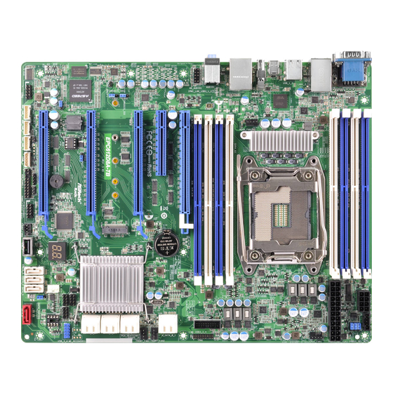
Page 13: Motherboard Layout
EPC612D8 Series 1.4 Motherboard Layout EPC612D8A-TB 24.4cm (9.6 in) PSU_SMB1 DDR4_C1 (64 bit, 288-pin module) DDR4_C2 (64 bit, 288-pin module) ATX12V1 DDR4_D1 (64 bit, 288-pin module) ATXPWR1 DDR4_D2 (64 bit, 288-pin module) CPU_FAN1 LAN1 LAN2 (NCSI) USB 2.0 T: USB_2... - Page 14 EPC612D8A 24.4cm (9.6 in) PSU_SMB1 DDR4_C1 (64 bit, 288-pin module) DDR4_C2 (64 bit, 288-pin module) ATX12V1 DDR4_D1 (64 bit, 288-pin module) ATXPWR1 DDR4_D2 (64 bit, 288-pin module) CPU_FAN1 LAN1 LAN2 (NCSI) USB 2.0 T: USB_2 B: USB_1 REAR_FAN1 USB 3.0...
- Page 15 EPC612D8 Series Description 2 x 288-pin DDR4 DIMM Slots (DDR4_C2, DDR4_D2, White) 2 x 288-pin DDR4 DIMM Slots (DDR4_C1, DDR4_D1, Blue) ATX 12V Power Connector (ATX12V1) PSU SMBus (PSU_SMB1) ATX Power Connector (ATXPWR1) CPU Fan Connector (CPU_FAN1) 2 x 288-pin DDR4 DIMM Slots (DDR4_A2, DDR4_B2, White) 2 x 288-pin DDR4 DIMM Slots (DDR4_A1, DDR4_B1, Blue) USB 3.0 Header (USB3_3_4) TPM Header (TPM1)
- Page 16 Description Thermal Sensor header (TR1) Auxiliary Panel Header (AUX_PANEL1) Speaker Header (SPEAKER1) Intelligent Platform Management Bus header (IPMB_1) BMC SMBus Header (BMC_SMB_3) BMC SMBus Header (BMC_SMB_2) BMC SMBus Header (BMC_SMB_1) Non Maskable Interrupt Button (NMI_BTN1) COM Port Header (COM2) Chassis ID0 Jumper (Chassis ID0) CPU PECI Jumper (PECI1) Chassis ID0 Jumper (Chassis ID1) HDMI_SPDIF Header (HDMI_SPDIF1)
- Page 17 EPC612D8 Series EPC612D8 24.4cm (9.6 in) PSU_SMB1 DDR4_C1 (64 bit, 288-pin module) DDR4_C2 (64 bit, 288-pin module) ATX12V1 DDR4_D1 (64 bit, 288-pin module) ATXPWR1 DDR4_D2 (64 bit, 288-pin module) CPU_FAN1 LAN1 LAN2 (NCSI) USB 2.0 T: USB_2 B: USB_1 REAR_FAN1 USB 3.0 DDR4_B2 (64 bit, 288-pin module) T: USB3_2...
- Page 18 Description 2 x 288-pin DDR4 DIMM Slots (DDR4_C2, DDR4_D2, White) 2 x 288-pin DDR4 DIMM Slots (DDR4_C1, DDR4_D1, Blue) ATX 12V Power Connector (ATX12V1) PSU SMBus (PSU_SMB1) ATX Power Connector (ATXPWR1) CPU Fan Connector (CPU_FAN1) 2 x 288-pin DDR4 DIMM Slots (DDR4_A2, DDR4_B2, White) 2 x 288-pin DDR4 DIMM Slots (DDR4_A1, DDR4_B1, Blue) USB 3.0 Header (USB3_3_4) TPM Header (TPM1)
- Page 19 EPC612D8 Series Description Thermal Sensor header (TR1) Auxiliary Panel Header (AUX_PANEL1) Speaker Header (SPEAKER1) Intelligent Platform Management Bus header (IPMB_1) BMC SMBus Header (BMC_SMB_3) BMC SMBus Header (BMC_SMB_2) BMC SMBus Header (BMC_SMB_1) Non Maskable Interrupt Button (NMI_BTN1) COM Port Header (COM2) Chassis ID0 Jumper (Chassis ID0) CPU PECI Jumper (PECI1) Chassis ID0 Jumper (Chassis ID1)
-
Page 20: I/O Panel
1.5 I/O Panel EPC612D8A-TB No. Description No. Description Serial Port (COM1) Display Port Input (DP_IN1) VGA Port (VGA1) LAN RJ-45 Port (IPMI_LAN)** LAN RJ-45 Port (LAN2)* USB 3.0 Ports (USB3_1-2) LAN RJ-45 Port (LAN1)* (NCSI) Front Speaker (Lime) USB 2.0 Ports (USB_1_2) - Page 21 EPC612D8 Series EPC612D8A No. Description No. Description Serial Port (COM1) LAN RJ-45 Port (IPMI_LAN)** VGA Port (VGA1) USB 3.0 Ports (USB3_1-2) LAN RJ-45 Port (LAN2)* Front Speaker (Lime) LAN RJ-45 Port (LAN1)* (NCSI) Microphone (Pink) USB 2.0 Ports (USB_1_2) Line In (Light Blue) EPC612D8 No.
- Page 22 LAN Port LED Indications *There are two LED next to the LAN port. Please refer to the table below for the LAN port LED indications. ACT/LINK LED SPEED LED LAN Port Dedicated IPMI LAN Port LED Indications Activity / Link LED Speed LED Status Description...
-
Page 23: Block Diagram
EPC612D8 Series 1.6 Block Diagram EPC612D8A-TB... - Page 24 EPC612D8A...
- Page 25 EPC612D8 Series EPC612D8...
-
Page 26: Chapter 2 Installation
Chapter 2 Installation This is an ATX form factor (12'' x 9.6'', 30.5 cm x 24.4 cm) motherboard. Before you install the motherboard, study the configuration of your chassis to ensure that the motherboard fits into it. Make sure to unplug the power cord before installing or removing the motherboard. Failure to do so may cause physical injuries to you and damages to motherboard components. -
Page 27: Installing The Cpu
EPC612D8 Series 2.3 Installing the CPU 6. Before you insert the 2011-3-Pin CPU into the socket, please check if the PnP cap is on the socket, if the CPU surface is unclean, or if there are any bent pins in the socket. Do not force to insert the CPU into the socket if above situation is found. - Page 29 EPC612D8 Series The cover must be placed if returning the motherboard for after service.
-
Page 30: Installing The Cpu Fan And Heatsink
2.4 Installing the CPU Fan and Heatsink Before you installed the heatsink, you need to spray thermal interface material between the CPU and the heatsink to improve heat dissipation. CPU fan for narrow ILM socket *Support an active or passive heatsink... -
Page 31: Installation Of Memory Modules (Dimm)
EPC612D8 Series 2.5 Installation of Memory Modules (DIMM) This motherboard provides eight 288-pin DDR4 (Double Data Rate 4) DIMM slots, and supports Dual Channel Memory Technology. 1. For dual channel configuration, you always need to install identical (the same brand, speed, size and chip-type) DDR4 DIMM pairs. -
Page 33: Expansion Slots (Pci And Pci Express Slots)
EPC612D8 Series 2.6 Expansion Slots (PCI and PCI Express Slots) There are 5 PCI Express slots on this motherboard. PCIE slot: PCIE6 (PCIE 3.0 x8 slot, from CPU) is used for PCI Express x8 lane width cards. PCIE1 and PCIE5 (PCIE 3.0 x16 slot, from CPU) are used for PCI Express x8 lane width cards. - Page 34 PCIe Slot Configurations (For CPU with 40 PCIe lanes) PCIE1 PCIE3 PCIE5 PCIE6 PCIE7 Single Graphics Card Two Graphics Cards in CrossFireX Mode Three Graphics Cards in 3-Way CrossFireX Mode PCIe Slot Configurations (For CPU with 28 PCIe lanes) PCIE1 PCIE3 PCIE7 Single Graphics Card...
-
Page 35: Installing An Expansion Card
EPC612D8 Series Installing an expansion card Step 1. Before installing an expansion card, please make sure that the power supply is switched off or the power cord is unplugged. Please read the documentation of the expansion card and make necessary hardware settings for the card before you start the installation. -
Page 36: Jumper Setup
2.7 Jumper Setup The illustration shows how jumpers are setup. When the jumper cap is placed on the pins, the jumper is “Short”. If no jumper cap is placed on the pins, the jumper is “Open”. The illustration shows a 3-pin jumper whose pin1 and pin2 are “Short” when a jumper cap is placed on these 2 pins. - Page 37 EPC612D8 Series Descriptor Security Over- ride Jumper Chassis ID0 Jumper (3-pin Chassis ID0) (see p.7, No. 43) Chassis ID1 Jumper (3-pin Chassis ID1 ) (see p.7, No. 45) Chassis ID2 Jumper (3-pin Chassis ID2) (see p.7, No. 47) Board Level SKU (Default) Reserved for system level Chassis ID0 Jumper (3-pin Chassis ID0)
- Page 38 Chassis ID0 Jumper (3-pin Chassis ID0) (see p.7, No. 43) Chassis ID1 Jumper (3-pin Chassis ID1 ) (see p.7, No. 45) Chassis ID2 Jumper (3-pin Chassis ID2) Reserved for system level Reserved for system level (see p.7, No. 47)
-
Page 39: Onboard Headers And Connectors
EPC612D8 Series 2.8 Onboard Headers and Connectors Onboard headers and connectors are NOT jumpers. Do NOT place jumper caps over these headers and connectors. Placing jumper caps over the headers and connectors will cause permanent damage to the motherboard. System Panel Header Connec t t he power sw itch, PLED+ PLED-... - Page 40 Auxiliary Panel Header This header supports multiple (18-pin AUX PANEL_1) functions on the front panel, (No. 35) including the front panel SMB, internet status indicator and chassis intrusion pin. A. Front panel SMBus connecting pin (6-1 pin FPSMB) This header allows you to connect SMBus (System Management Bus) equipment. It can be used for communication between peripheral equipment in the system, which has slower transmission rates, and power management equipment.
- Page 41 EPC612D8 Series Serial ATA3 Connectors These eight SATA3 connectors (White) support SATA data cables for (SATA_1) internal storage devices with (No. 18) up to 6.0 Gb/s data transfer (SATA_2) rate. (No. 17) (SATA_3) (No. 16) (SATA_4) (No. 15) (SATA_5) (No. 27) (SSATA_0) (No.
- Page 42 USB 2.0 Header B e side s t wo USB 2 .0 p or t s USB_PWR (9-pin USB_3_4) on the I/O panel, there is one DUMMY (No. 22) header on this motherboard. E a c h U S B 2 . 0 h e a d e r c a n support two ports.
- Page 43 EPC612D8 Series Front Panel Audio Header This is an interface for the PRESENCE# (9-pin HD_AUDIO1) front panel audio cable that MIC_RET (No. 48) allows convenient connection OUT_RET *Not supported for EPC612D8T and control of audio devices. motherboard OUT2_L J_SENSE OUT2_R MIC2_R MIC2_L 1.
- Page 44 Front and Rear Fan Please connect fan cables to the FAN_SPEED_CONTROL Connectors FAN_SPEED fan connectors and match the FAN_VOLTAGE (4-pin FRONT_FAN1) black wire to the ground pin. (No. 14) All fans support Fan Control. (4-pin FRONT_FAN2) (No. 13) (4-pin FRONT_FAN3) (No.
- Page 45 EPC612D8 Series Serial Port Header This COM2 header supports RRXD1 DDTR#1 (9-pin COM2) a serial port module. DDSR#1 CCTS#1 (No. 42) RRI#1 RRTS#1 TTXD1 DDCD#1 TPM Header This connector supports (17-pin TPM1) Trusted Platform Module (No. 10) (TPM) system, which can securely store keys, digital certificates, passwords, and data.
- Page 46 Intelligent Platform No connect This 4-pin connector is used Management Bus header to provide a cabled base-board (4-pin IPMB_1) or front panel connection for (No. 37) IPMB_SCL value added features and 3rd- IPMB_SDA party add-in cards, such as Emergency Management cards, t h a t p r o v i d e m a n a g e m e n t features using the IPMB.
-
Page 47: Dr. Debug
EPC612D8 Series 2.9 Dr. Debug Dr. Debug is used to provide code information, which makes troubleshooting even easier. Please see the diagrams below for reading the Dr. Debug codes. Code Description Please check if the CPU is installed correctly and then clear CMOS. Problem related to memory, VGA card or other devices. -
Page 48: Driver Installation Guide
2.10 Driver Installation Guide To install the drivers to your system, please insert the support CD to your optical drive first. Then, the drivers compatible to your system can be auto-detected and listed on the support CD driver page. Please follow the order from top to bottom to install those required drivers. -
Page 49: Displayport Input
EPC612D8 Series 2.12 DisplayPort Input The DisplayPort Input on the motherboard allows you to utilize the power of discrete graphics with a Thunderbolt™ display connected. Connection Diagram ( Using Graphics card with DisplayPort) DisplayPort 1. Connect one end of the DisplayPort Cable to the DisplayPort of the graphics card. Then connect the other end of the cable to the DisplayPort Input on the rear I/O panel. -
Page 50: Dual Lan And Teaming Operation Guide
2.11 Dual LAN and Teaming Operation Guide Dual LAN with Teaming enabled on this motherboard allows two single connections to act as one single connection for twice the transmission bandwidth, making data transmission more effective and improving the quality of transmission of distant images. Fault tolerance on the dual LAN network prevents network downtime by transferring the workload from a failed port to a working port. -
Page 51: M.2_Ssd (Ngff) Module Installation Guide
EPC612D8 Series 2.12 M.2_SSD (NGFF) Module Installation Guide The M.2, also known as the Next Generation Form Factor (NGFF), is a small size and versatile card edge connector that aims to replace mPCIe and mSATA. The M.2_SSD (NGFF) Socket 3 can accommodate either a M.2 SATA3 6.0 Gb/s module or a M.2 PCI Express module up to Gen 2 x2 (10 Gb/s). - Page 52 Step 3 Move the standoff based on the module type and length. The standoff is placed at the nut location D by default. Skip Step 3 and 4 and go straight to Step 5 if you are going to use the default nut. Otherwise, release the standoff by hand.
- Page 53 EPC612D8 Series M.2_SSD (NGFF) Module Support List PCIe Interface SATA Interface Plextor PX-G512M6e ADATA AXNS381E-128GM-B Plextor PX-G256M6e ADATA AXNS381E-256GM-B SanDisk SD6PP4M-128G Crucial CT120M500SSD4/120G SanDisk SD6PP4M-256G Crucial CT240M500SSD4/240G Samsung XP941-512G (MZHPU512HCGL) Intel SSDSCKGW080A401/80G Kingston RBU-SM2280S3/120G For the latest updates of M.2_SSD (NFGG) module support list, please visit our website for details: http://www.asrockrack.com...
-
Page 54: Chapter 3 Uefi Setup Utility
Chapter 3 UEFI Setup Utility 3.1 Introduction Th is section explains how to use the UEFI SETUP UTILITY to confi gure your system. Th e UEFI chip on the motherboard stores the UEFI SETUP UTILITY. You may run the UEFI SETUP UTILITY when you start up the computer. -
Page 55: Navigation Keys
EPC612D8 Series 3.1.2 Navigation Keys Please check the following table for the function description of each navigation key. Navigation Key(s) Function Description Moves cursor left or right to select Screens Moves cursor up or down to select items + / - To change option for the selected items <Tab>... -
Page 56: Main Screen
3.2 Main Screen Once you enter the UEFI SETUP UTILITY, the Main screen will appear and display the system overview. The Main screen provides system overview information and allows you to set the system time and date. -
Page 57: Oc Tweaker Screen
EPC612D8 Series 3.3 OC Tweaker Screen In the OC Tweaker screen, you can set up overclocking features. Because the UEFI software is constantly being updated, the following UEFI setup screens and descriptions are for reference purpose only, and they may not exactly match what you see on your screen. -
Page 58: Long Duration Maintained
Intel SpeedStep Technology Intel SpeedStep technology allows processors to switch between multiple frequen- cies and voltage points for better power saving and heat dissipation. Intel Turbo Boost Technology Intel Turbo Boost Technology enables the processor to run above its base operating frequency when the operating system requests the highest performance state. -
Page 59: Dram Configuration
EPC612D8 Series Configure the dynamic Vcore voltage added to the Vcore. CPU Cache Voltage Mode Configure the amount of voltage fed to the UNCores of the processor including its cache. Increase the voltage when increasing CPU Cache Frequency. CPU Cache Adaptive Voltage Configure the voltage added to the CPU Cache when the system is under heavy load. -
Page 60: Advanced Screen
3.4 Advanced Screen In this section, you may set the configurations for the following items: CPU Configuration, DRAM Configuration, ACPI Configuration, Configure Super IO Settings, Serial Port Con- sole Redirection, USB Configuration, Chipset Configuration, Storage Configuration, H/W Monitor, Intel ME Configuration, Easy RAID Installer and Instant Flash. Setting wrong values in this section may cause the system to malfunction. -
Page 61: Cpu Configuration
EPC612D8 Series 3.4.1 CPU Configuration Intel SpeedStep Technology Intel SpeedStep technology allows processors to switch between multiple frequencies and voltage points for better power saving and heat dissipation. Intel Turbo Boost Technology Intel Turbo Boost Technology enables the processor to run above its base operating frequency when the operating system requests the highest performance state. -
Page 62: Intel Virtualization Technology
Short Duration Power Limit Configure Package Power Limit 2 in watts. When the limit is exceeded, the CPU ratio will be lowered immediately. A lower limit can protect the CPU and save power, while a higher limit may improve performance. Intel Hyper Threading Technology Intel Hyper Threading Technology allows multiple threads to run on each core, so that the overall performance on threaded software is improved. - Page 63 EPC612D8 Series CPU C States Support Enable CPU C States Support for power saving. It is recommended to keep C3 and C6 enabled for better power saving. Package C State Support Enable CPU, PCIe, Memory, Graphics C State Support for power saving. CPU C3 State Support Enable C3 sleep state for lower power consumption.
-
Page 64: Dram Configuration
3.4.2 DRAM Configuration DRAM Frequency If [Auto] is selected, the motherboard will detect the memory module(s) inserted and as- sign the appropriate frequency automatically. ECC Support This allows you to enable or disable the DDR ECC support feature. Channel Interleaving Use this item to select Channel Interleaving setting. -
Page 65: Acpi Configuration
EPC612D8 Series 3.4.3 ACPI Configuration Suspend to RAM Use this item to select whether to auto-detect or disable the Suspend-to-RAM feature. Se- lecting [Auto] will enable this feature if the OS supports it. Ring-In Power On Use this item to enable or disable Ring-In signals to turn on the system from the power- soft-off mode. - Page 66 off mode. Wake From Onboard LAN 2 It allows the system to be waked up by the Onboard Intel LAN.
-
Page 67: Configure Super Io Settings
EPC612D8 Series 3.4.4 Configure Super IO Settings Serial Port 1 Configuration Use this item to configure the onboard serial port 1. Select and enter the "Serial Port 1 Configuration" and you will see the followings: Serial Port Use this item to enable or disable the onboard serial port. Change Settings Use this item to select an optimal setting for Super IO device. -
Page 68: Serial Port Console Redirection
3.4.5 Serial Port Console Redirection Console Redirection Use this option to enable or disable Console Redirection. If this item is set to Enabled, you can select a COM Port to be used for Console Redirection. Console Redirection Settings Use this option to configure Console Redirection Settings, and specify how your computer and the host computer to which you are connected exchange information. - Page 69 EPC612D8 Series Data Bits Use this item to set the data transmission size. The options include [7] and [8] (Bits). Parity Use this item to select the parity bit. The options include [None], [Even], [Odd], [Mark] and [Space]. Stop Bits The item indicates the end of a serial data packet.
-
Page 70: Usb Configuration
3.4.6 USB Configuration Intel USB3.0 Mode Use this item to select the mode of operation of Intel USB3.0 controller. Legacy USB 3.0 Support Use this item to enable or disable Legacy OS Support for USB 3.0 devices. -
Page 71: Chipset Configuration
EPC612D8 Series 3.4.7 Chipset Configuration Intel(R) Thunderbolt (Only for EPC612D8A-TB motherboard) Intel Thunderbolt™ Technology Enable or disable the Intel® Thunderbolt™ function. Security Level Select Legacy to skip the Windows certification checking process for Thunderbolt™devices. Select Unique ID for checking the Windows certification, and showwarning messages if the devices aren't certified. -
Page 72: Onboard Vga
Onboard VGA Use this to enable or disable the Onboard VGA function. The default value is [Auto]. *This item is not available when the Primary Graphic Adapter is set to [Onboard]. VT-d Intel Virtualization Technology for Directed I/O helps your virtual machine monitor bet- ter utilize hardware by improving application compatibility and reliability, and providing additional levels of manageability, security, isolation, and I/O performance. -
Page 73: Above 4G Decoding
This allows you to enable or disable the Onboard LAN 2 feature. Onboard HD Audio (Only for EPC612D8A-TB / EPC612D8A motherboard) Use this item to automatically enable or disable onboard HD audio. Set to Auto to enable onboard HD audio and automatically disable it when a sound card is installed. -
Page 74: Storage Configuration
3.4.8 Storage Configuration Hard Disk S.M.A.R.T. Use this item to enable or disable the S.M.A.R.T. (Self-Monitoring, Analysis, and Reporting Technology) feature. Configuration options: [Disabled] and [Enabled]. SATA Storage Configuration SATA Controller Use this item to enable or disable SATA Controller. SATA Mode Selection Use this to select SATA mode. -
Page 75: Hot Plug
EPC612D8 Series SATA Port 0 / 1 / 2 / 3 / 4 / 5 Depending on how many SATA ports you have, you will see SATA_x (x means number) listed on the screen, with its status indicated as SATA device [(Model Name)] or [Not Detected]. -
Page 76: Rd Storage Configuration
Detected]. External sSATA Use this item to enable SATA safe removal notifications. Please note that the SATA device will be downgraded to SATA2. Hot Plug Designates this port as Hot Plugglable. Spin Up Device If enabled for any of ports, Staggered Spin Up will be performed and only the drives which have this option enabled will spin up at boot. -
Page 77: H/W Monitor Screen
EPC612D8 Series 3.4.9 H/W Monitor Screen In this section, it allows you to monitor the status of the hardware on your system, includ- ing the parameters of the CPU temperature, motherboard temperature, CPU fan speed, chassis fan speed, and the critical voltage. CPU_FAN 1 This allows you to set the CPU fan 1’s speed. -
Page 78: Watch Dog Timer
Smart Fan Control This allows you to set the Smart fan’s level speed. Smart Fan Duty Control Smart Fan Duty x (x means 1 to 11 stage) This allows you to set duty cycle for each stage. Smart Fan Temp Control Smart Fan Temp x (x means 1 to 11 stage) This allows you to set temperature for each stage. -
Page 79: Intel Me Configuration
EPC612D8 Series 3.4.10 Intel ME Configuration ME Subsystem screen displays the Intel ME Subsystem Configuration information, such as Operational Firmware Version, ME Firmware, ME Firmware Type, ME Firmware SKU and ME File System Integrity Vaalue. -
Page 80: Easy Raid Installer
3.4.11 Easy RAID Installer Easy RAID Installer can help you to copy the RAID driver from a support CD to your USB storage device. After copying the RAID driver to your USB storage device, please change “SATA Mode” to “RAID”, then you can start installing the OS in RAID mode. -
Page 81: Instant Flash
EPC612D8 Series 3.4.12 Instant Flash Instant Flash is a UEFI flash utility embedded in Flash ROM. This convenient UEFI update tool allows you to update system UEFI without entering operating systems ® first like MS-DOS or Windows . Just save the new UEFI file to your USB flash drive, floppy disk or hard drive and launch this tool, then you can update your UEFI only in a few clicks without preparing an additional floppy diskette or other compli- cated flash utility. -
Page 82: Server Mgmt (Server Management)
3.5 Server Mgmt (Server Management) Wait For BMC Wait For BMC response for specified time out. In PILOTII, BMC starts at the same time when BIOS starts during AC power ON. It takes around 30 seconds to initialize Host to BMC interfaces. -
Page 83: Bmc Network Configuration
EPC612D8 Series BMC Network Configuration Enter to configure BMC Network parameters. Configuration Address Source Select to configure BMC network parameters statically or dynamically(by BIOS or BMC). Configuration options: [Unspecified], [Static], and [Dynamic]. Unspecified: BMC network parameters are configured by BMC itself. Static: Manually enter the IP Address, Subnet Mask and Gateway Address in the BIOS for BMC LAN channel configuration. -
Page 84: Security Screen
3.6 Security Screen In this section, you may set or change the supervisor/user password for the system. For the user password, you may also clear it. Supervisor Password Set or change the password for the administrator account. Only the administrator has authority to change the settings in the UEFI Setup Utility. -
Page 85: Boot Screen
EPC612D8 Series 3.7 Boot Screen In this section, it will display the available devices on your system for you to configure the boot settings and the boot priority. Boot Option #1 Use this item to set the system boot order. Fast Boot Enables or disables boot with initialization of a minimal set of devices required to launch active boot option. - Page 86 Full Screen Logo Use this item to enable or disable OEM Logo. The default value is [Enabled]. AddOn ROM Display Use this option to adjust AddOn ROM Display. If you enable the option “Full Screen Logo” but you want to see the AddOn ROM information when the system boots, please select [Enabled].
-
Page 87: Event Logs
EPC612D8 Series 3.8 Event Logs Change Smbios Event Log Settings This allows you to configure the Smbios Event Log Settings. When entering the item, you will see the followings: Smbios Event Log Use this item to enable or disable all features of the SMBIOS Event Logging during system boot. -
Page 88: View Smbios Event Log
entries which utilize a multiple-event counter. The value ranges from 0 to 99 minutes. View Smbios Event Log This allows you to view the Smbios Event Log records. All values changed here do not take effect until computer is restarted. -
Page 89: Exit Screen
EPC612D8 Series 3.9 Exit Screen Save Changes and Exit When you select this option, the following message “Save configuration changes and exit setup?” will pop-out. Select [Yes] to save the changes and exit the UEFI SETUP UTILITY. Discard Changes and Exit When you select this option, the following message “Discard changes and exit setup?”... -
Page 90: Chapter 4 Software Support
4.2.4 Contact Information If you need to contact ASRock Rack or want to know more about ASRock Rack, welcome to visit ASRock Rack’s website at http://www.ASRockRack.com; or you may contact your... -
Page 91: Chapter 5 Troubleshooting
EPC612D8 Series Chapter 5 Troubleshooting 5.1 Troubleshooting Procedures Follow the procedures below to troubleshoot your system. Always unplug the power cord before adding, removing or changing any hardware com- ponents. Failure to do so may cause physical injuries to you and damages to motherboard components. - Page 92 1. Verify if the battery on the motherboard provides ~3VDC. Install a new battery if it does not. 2. Confirm whether your power supply provides adaquate and stable power. Other problems... 1. Try searching keywords related to your problem on ASRock Rack’s FAQ page: http://www.asrockrack.com/support...
-
Page 93: Technical Support Procedures
EPC612D8 Series 5.2 Technical Support Procedures If you have tried the troubleshooting procedures mentioned above and the problems are still unsolved, please contact ASRock Rack’s technical support with the following information: 1. Your contact information 2. Model name, BIOS version and problem type. -
Page 94: Chapter 6: Net Framework Installation Guide
Chapter 6: Net Framework Installation Guide ® To let Intel RSTe works properly, it is required to install Net Framework. Please follow the ® ® steps below to enable “.Net Framework” feature on Microsoft Windows Server 2008 R2. 6.1 Installing .Net Framework 3.5.1 (For Server 2008 R2) 1. - Page 95 EPC612D8 Series 3. Check the box next to .Net Framework 3.5.1 and then click Next. 4. Click Next to continue.
- Page 96 P/N: 15G065023000AK V1.0 5. Click Install to start installing .Net Framework 3.5.1. 6. After the installation completes, click Close.
Need help?
Do you have a question about the EPC612D8A and is the answer not in the manual?
Questions and answers