
Related Manuals for ASROCK EPC621D6U


Summary of Contents for ASROCK EPC621D6U
- Page 1 EPC621D6U EPC621D6U-16R EPC621D6U-2T EPC621D6U-2T16R User Manual Version 1.0 Published March 2019 Copyright©2019 ASRock Rack INC. All rights reserved.
- Page 2 (including damages for loss of profits, loss of business, loss of data, interruption of business and the like), even if ASRock Rack has been advised of the possibility of such damages arising from any defect or error in the documentation or product.
- Page 3 Contact Information If you need to contact ASRock Rack or want to know more about ASRock Rack, you’re welcome to visit ASRock Rack’s website at www.ASRockRack.com; or you may contact your dealer for further information. ASRock Rack Incorporation 6F., No.37, Sec. 2, Jhongyang S. Rd., Beitou District,...
-
Page 4: Table Of Contents
Contents Chapter 1 Introduction Package Contents Specifications Unique Features Motherboard Layout Onboard LED Indicators I/O Panel Block Diagram Chapter 2 Installation Screw Holes Pre-installation Precautions Installing the CPU and Heatsink Installation of Memory Modules (DIMM) Expansion Slots (PCI Express Slots) Jumper Setup Onboard Headers and Connectors Unit Identification purpose LED/Switch... - Page 5 Main Screen Advanced Screen 3.3.1 CPU Configuration 3.3.2 DRAM Configuration 3.3.3 Chipset Configuration 3.3.4 Storage Configuration 3.3.5 ACPI Configuration 3.3.6 USB Configuration 3.3.7 Super IO Configuration 3.3.8 Serial Port Console Redirection 3.3.9 H/W Monitor 3.3.10 Runtime Error Logging 3.3.11 Intel SPS Configuration ®...
- Page 6 Exit Screen Chapter 4 Software Support Install Operating System Support CD Information 4.2.1 Running The Support CD 4.2.2 Drivers Menu 4.2.3 Utilities Menu 4.2.4 Contact Information Chapter 5 Troubleshooting Troubleshooting Procedures Technical Support Procedures Returning Merchandise for Service...
-
Page 7: Chapter 1 Introduction
In case any modifications of this manual occur, the updated version will be available on ASRock Rack website without further notice. You may find the latest memory and CPU support lists on ASRock Rack website as well. ASRock Rack’s Website: www.ASRockRack.com If you require technical support related to this motherboard, please visit our website for specific information about the model you are using. -
Page 8: Specifications
1.2 Specifications EPC621D6U / EPC621D6U-16R / EPC621D6U-2T / EPC621D6U-2T16R MB Physical Status Form Factor micro-ATX Dimension 9.6'' x 9.6'' (24.4 cm x 24.4 cm) Processor System Intel® Xeon® Scalable Processors Socket Single Socket P (3647) Chipset Intel® C621 System Memory Capacity... - Page 9 EPC621D6U Series EPC621D6U / EPC621D6U-2T: Additional Storage Controller EPC621D6U-16R / EPC621D6U-2T16R: LSI3616 (shared with PCIE Slot4) U.2 from 1 (Slimline x8 from CPU1) Slimline Ethernet EPC621D6U / EPC621D6U-16R: Interface 1000 /100 /10 Mbps EPC621D6U-2T / EPC621D6U-2T16R: 10000/1000 /100 Mbps EPC621D6U / EPC621D6U-16R: - 2 x RJ45 1G base-T by Intel®...
- Page 10 256Mb AMI UEFI Legal BIOS BIOS Features - Plug and Play (PnP) - ACPI 2.0 Compliance Wake Up Events - SMBIOS 2.8 Support - ASRock Rack Instant Flash Hardware Monitor Temperature - CPU Temperature Sensing - SystemTemperature Sensing - CPU/Rear/Front Fan Tachometer...
- Page 11 EPC621D6U Series Support OS Microsoft® Windows® (Server OS) - Server 2012 R2 (64 bit) - Server 2016 (64 bit) Linux® - Red Hat Enterprise Linux Server 6.8 ( 64 bit) / 7.4 ( 64 bit) - CentOs 6.8 ( 64 bit) / 7.4 ( 64 bit)
-
Page 12: Unique Features
POST or the <F2> key to enter into the BIOS setup menu to access ASRock Rack Instant Flash. Just launch this tool and save the new BIOS file to your USB flash drive, floppy disk or hard drive, then you can update your BIOS only in a few clicks without preparing an additional floppy diskette or other complicated flash utility. -
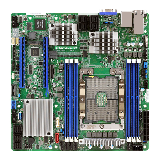
Page 13: Motherboard Layout
(EPC621D6U-16R / (EPC621D6U-2T / CPU1 EPC621D6U-2T16R only) EPC621D6U-2T16R) / i350 (EPC621D6U / EPC621D6U-16R) SAS_NVMEA0_7 (EPC621D6U-16R / EPC621D6U-2T16R only) SAS_NVMEB0_7 FRNT_FAN1 (EPC621D6U-16R / EPC621D6U-2T16R only) DDR4_D1 (64 bit, 288-pin module, Blue) FRNT_FAN2 DDR4_E1 (64 bit, 288-pin module, Blue) FRNT_FAN3 LSI 3616... - Page 14 Description Rear Fan Connector (REAR_FAN1) CPU PECI Mode Jumper (PECI1) Descriptor Security Override Jumper (J100) Chassis ID0 Jumper (CHASSIS_ID0) Enable/Disable BMC Jumper (BMC_DIS1) Chassis ID1 Jumper (CHASSIS_ID1) Chassis ID2 Jumper (CHASSIS_ID2) PSU SMBus (PSU_SMB1) ATX Power Connector (ATXPWR1) DIMM Mode Jumper (AEP_1) ATX 12V Power Connector (ATX12V1) 3 x 288-pin DDR4 DIMM Slots (DDR4_A1, DDR4_B1, DDR4_C1, Blue)* CPU1 Fan Connector (CPU1_FAN1)
- Page 15 M.2 Slot (M2_1) (Type 2230 / 2242 / 2260 / 2280) PCI Express 3.0 Slot (PCIE6) Slimline for U.2 x8 Connector (SLIMLIN1) Mini-SAS HD Connector (NVME) (SAS_NVMEB0_7) (EPC621D6U-16R / EPC621D6U-2T16R only) Mini-SAS HD Connector (NVME) (SAS_NVMEA0_7) (EPC621D6U-16R / EPC621D6U-2T16R only) SATA/SAS and NVMe Mode Selection Jumper (SAS_CT_1)
-
Page 16: Onboard Led Indicators
DDR4_A1 (64 bit, 288-pin module, Blue) CPU1 FRNT_FAN1 DDR4_D1 (64 bit, 288-pin module, Blue) FRNT_FAN2 DDR4_E1 (64 bit, 288-pin module, Blue) FRNT_FAN3 LSI 3616 DDR4_F1 (64 bit, 288-pin module, Blue) FRNT_FAN4 (EPC621D6U-16R / EPC621D6U-2T16R only) PCIE6 Intel NUT30 NUT42 NUT60 NUT80 C621... - Page 17 FRNT_FAN1 failed FFAN_LED2 Amber FRNT_FAN2 failed FFAN_LED3 Amber FRNT_FAN3 failed FFAN_LED4 Amber FRNT_FAN4 failed SB_PWR1 Green STB PWR ready BMC_LED1 Green BMC heartbeat LED System Heartbeat LED SAS_SYS_LED1 Green (EPC621D6U-16R / EPC621D6U-2T16R only) IOC Overtemp LED SAS_IOC_LED1 (EPC621D6U-16R / EPC621D6U-2T16R only)
-
Page 18: I/O Panel
1.6 I/O Panel No. Description No. Description UID Switch (UID) USB 3.0 Ports (USB3_1_2) LAN RJ-45 Port (LAN1)* LAN RJ-45 Port (IPMI_LAN1)* LAN RJ-45 Port (LAN2)* VGA Port (VGA1) *There are two LED next to the LAN port. Please refer to the table below for the LAN port LED indications. - Page 19 **There are two LEDs on each LAN port. Please refer to the table below for the LAN port LED indications. SPEED LED ACT/LIN K LED SPEED LED ACT/LIN K LED LAN Port LAN Port (LAN1, LAN2) LED Indications EPC621D6U / EPC621D6U-16R: Activity / Link LED Speed LED Status Description Status Description No Link...
-
Page 20: Block Diagram
1.7 Block Diagram... -
Page 21: Chapter 2 Installation
EPC621D6U Series Chapter 2 Installation This is a micro-ATX form factor (9.6” x 9.6”, 24.4 cm x 24.4 cm) motherboard. Before you install the motherboard, study the configuration of your chassis to ensure that the motherboard fits into it. Make sure to unplug the power cord before installing or removing the motherboard. Failure to do so may cause physical injuries to you and damages to motherboard components. -
Page 22: Installing The Cpu And Heatsink
2.3 Installing the CPU and Heatsink 1. Before you insert the CPU into the socket, please check if the PnP cap is on the socket, if the CPU surface is unclean, or if there are any bent pins in the socket. Do not force to insert the CPU into the socket if above situation is found. - Page 23 EPC621D6U Series 1. Before you installed the heatsink, you need to spray thermal interface material between the CPU and the heatsink to improve heat dissipation. 2. Illustration in this documentation are examples only. Heatsink or fan cooler type may differ.
- Page 25 EPC621D6U Series Tighten the two Corner Plunger to 12 IN.LB. Two turns at a time. Tighten the two Middle Nuts to 12 IN.LB. Two turns at a time.
-
Page 26: Installation Of Memory Modules (Dimm)
2.4 Installation of Memory Modules (DIMM) This motherboard provides six 288-pin DDR4 (Double Data Rate 4) DIMM slots in two groups, and supports Six Channel Memory Technology. The DIMM only fits in one correct orientation. It will cause permanent damage to the motherboard and the DIMM if you force the DIMM into the slot at incorrect orientation. -
Page 27: Expansion Slots (Pci Express Slots)
Source PCIE6 CPU1 PCIE4 CPU1 EPC621D6U-16R / EPC621D6U-2T16R only: The SAS_NVMEA0_7 and SAS_NVMEB0_7 are shared with the PCIE4 slot. When PCIE4 is populated with a PCIE card, SAS_NVMEA0_7 and SAS_NVMEB0_7 are disabled. Installing an expansion card Step 1. Before installing an expansion card, please make sure that the power supply is switched off or the power cord is unplugged. -
Page 28: Jumper Setup
2.6 Jumper Setup The illustration shows how jumpers are setup. When the jumper cap is placed on the pins, the jumper is “Short”. If no jumper cap is placed on the pins, the jumper is “Open”. The illustration shows a 3-pin jumper whose pin1 and pin2 are “Short” when a jumper cap is placed on these 2 pins. - Page 29 EPC621D6U Series Chassis ID0 Jumper (3-pin CHASSIS_ID0) (see p.7, No. 4) Chassis ID1 Jumper (3-pin CHASSIS_ID1) (see p.7, No. 6) Chassis ID2 Jumper (3-pin CHASSIS_ID2) (see p.7, No. 7) Board Level SKU (Default) Reserved for system level Chassis ID0 Jumper (3-pin CHASSIS_ID0) (see p.7, No.
- Page 30 DIMM Mode Jumpers (3-pin AEP_1) (see p.7, No. 10) Normal Mode (Default) NVDIMM Mode (3-pin AEP_2) (see p.7, No. 20) EPC621D6U-16R / EPC621D6U-2T16R Only: SATA/SAS and NVMe Mode Selection Jumpers (3-pin SAS_BP_1) (see p.7, No. 49) NVMe Mode: SATA/SAS Mode:...
-
Page 31: Onboard Headers And Connectors
EPC621D6U Series 2.7 Onboard Headers and Connectors Onboard headers and connectors are NOT jumpers. Do NOT place jumper caps over these headers and connectors. Placing jumper caps over the headers and connectors will cause permanent damage to the motherboard. System Panel Header... - Page 32 Auxiliary Panel Header This header supports multiple (18-pin AUX_PANEL1) functions on the front panel, (see p.7, No. 37) including the front panel SMB, internet status indicator and chassis intrusion pin. A. Front panel SMBus connecting pin (6-1 pin FPSMB) This header allows you to connect SMBus (System Management Bus) equipment. It can be used for communication between peripheral equipment in the system, which has slower transmission rates, and power management equipment.
- Page 33 EPC621D6U Series Serial ATA3 Connector The SATA3 connector supports SSATA_4 (SSATA_4) SATA data cables for internal (see p.7, No. 23) storage devices with up to 6.0 Gb/s data transfer rate. Mini-SAS HD Connectors These connectors (SATA_0_7) support MiniSAS-to- (see p.7, No. 27)
- Page 34 6 -P i n C PU f a n (Q u ie t FAN_SPEED FAN_VOLTAGE (see p.7, No. 13) Fan) connector. If you plan to connect a 3-Pin CPU fan, please connect it to Pin 1-3. *For more details, please refer to the Cooler QVL list on the ASRock Rack website.
- Page 35 EPC621D6U Series ATX Power Connector This motherboard provides a (24-pin ATXPWR1) 24-pin ATX power connector. (see p.7, No. 9) To use a 20-pin ATX power supply, please plug it along Pin 1 and Pin 13. ATX 12V Power This motherboard provides...
- Page 36 BMC_SMB_PRESENT_1_N Baseboard Management The header is used for the SM Power Controller SMBus Header BUS devices. BMC_SMBCLK (5-pin BMC_SMB_1) BMC_SMBDATA (see p.7, No. 38) Thermal Sensor Header Please connect the thermal (3-pin TR1) sensor cable to either pin 1-2 (see p.7, No. 33) or pin 2-3 and the other end to the device which you wish to monitor its temperature.
- Page 37 EPC621D6U Series Virtual RAID On CPU This connector supports Intel® Header Virtual RAID on CPU and VROC RAID KEY (4-pin RAID_1) NVME/AHCI RAID on CPU (see p.7, No. 34) PCIE. +3VSB With the introduction of the Intel VROC product, there are three modes of operation:...
-
Page 38: Unit Identification Purpose Led/Switch
2.8 Unit Identification purpose LED/Switch With the UID button, You are able to locate the server you’re working on from behind a rack of servers. Unit Identification When the UID button on the purpose LED/Switch front or rear panel is pressed, (UID1) the front/rear UID blue LED indicator will be truned on. -
Page 39: M.2_Ssd (Ngff) Module Installation Guide
EPC621D6U Series 2.10 M.2_SSD (NGFF) Module Installation Guide The M.2, also known as the Next Generation Form Factor (NGFF), is a small size and versatile card edge connector that aims to replace mPCIe and mSATA. The M.2_SSD (NGFF) Socket 3 can accommodate either a M.2 SATA3 6.0 Gb/s module or a M.2 PCI Express module up to Gen3 x4 (32 Gb/s). - Page 40 Step 3 Move the standoff based on the module type and length. The standoff is placed at the nut location D by default. Skip Step 3 and 4 and go straight to Step 5 if you are going to use the default nut. Otherwise, release the standoff by hand.
-
Page 41: Chapter 3 Uefi Setup Utility
EPC621D6U Series Chapter 3 UEFI Setup Utility 3.1 Introduction Th is section explains how to use the UEFI SETUP UTILITY to confi gure your system. Th e UEFI chip on the motherboard stores the UEFI SETUP UTILITY. You may run the UEFI SETUP UTILITY when you start up the computer. -
Page 42: Navigation Keys
3.1.2 Navigation Keys Please check the following table for the function description of each navigation key. Navigation Key(s) Function Description Moves cursor left or right to select Screens Moves cursor up or down to select items + / - To change option for the selected items <Tab>... -
Page 43: Main Screen
EPC621D6U Series 3.2 Main Screen Once you enter the UEFI SETUP UTILITY, the Main screen will appear and display the system overview. The Main screen provides system overview information and allows you to set the system time and date. -
Page 44: Advanced Screen
3.3 Advanced Screen In this section, you may set the configurations for the following items: CPU Configuration, DRAM Configuration, Chipset Configuration, Storage Configuration, ACPI Configura- tion, USB Configuration, Super IO Configuration, Serial Port Console Redirection, H/W Monitor, Runtime Error Logging, Intel SPS Configuration, Intel®... -
Page 45: Cpu Configuration
EPC621D6U Series 3.3.1 CPU Configuration Intel SpeedStep Technology Intel SpeedStep technology allows processors to switch between multiple frequencies and voltage points for better power saving and heat dissipation. CPU turbo ratio can be fixed when Intel SpeedStep Technology set Disabled and Intel Turbo Boost Technology set En- abled. - Page 46 Short Duration Power Limit Configure Package Power Limit 2 in watts. When the limit is exceeded, the CPU ratio will be lowered immediately. A lower limit can protect the CPU and save power, while a higher limit may improve performance. Intel Hyper Threading Technology Intel Hyper Threading Technology allows multiple threads to run on each core, so that the overall performance on threaded software is improved.
- Page 47 EPC621D6U Series CPU C6 State Support Enable C6 deep sleep state for lower power consumption. Enhanced Halt State (C1E) Enable Enhanced Halt State (C1E) for lower power consumption. Hardware P-States Disable: Hardware chooses a P-state based on OS Request (Legacy P-States)
-
Page 48: Dram Configuration
3.3.2 DRAM Configuration Enforce POR Enable to enforce POR restrictions for DDR4 frequency and voltage programming. DRAM Frequency If [Auto] is selected, the motherboard will detect the memory module(s) inserted and assign the appropriate frequency automatically. Channel Interleaving Select to configure Channel Interleaving settings. Rank Interleaving Select to configure Rank Interleaving settings. -
Page 49: Chipset Configuration
EPC621D6U Series 3.3.3 Chipset Configuration MMCFG Base Use this item to select MMCFG Base. MMIO High Base Use this item to select MMIO High Base. MMIO High Size Use this item to select MMIO High Size. Above 4G Decoding Enable or disable 64bit capable Devices to be decoded in Above 4G Address Space (only if the system supports 64 bit PCI decoding). - Page 50 Onboard LAN 1 (EPC621D6U-16R / EPC621D6U only) This allows you to enable or disable the Onboard LAN feature. Onboard LAN 2 (EPC621D6U-16R / EPC621D6U only) This allows you to enable or disable the Onboard LAN feature. Onboard LAN (EPC621D6U-2T16R / EPC621D6U-2T only) This allows you to enable or disable the Onboard LAN feature.
- Page 51 EPC621D6U Series SLIMELIN1-1 ASPM Support This option enables or disables the ASPM support for all CPU downstream devices. SLIMELIN1-2 Link Speed This allows you to select SLIMLIN1-2 Link Speed. The default value is [Auto]. SLIMELIN1-2 ASPM Support This option enables or disables the ASPM support for all CPU downstream devices.
-
Page 52: Storage Configuration
3.3.4 Storage Configuration Hard Disk S.M.A.R.T. Use this item to enable or disable the S.M.A.R.T. (Self-Monitoring, Analysis, and Reporting Technology) feature. Configuration options: [Disabled] and [Enabled]. SATA Controller Use this item to enable or disable SATA Controllers. SATA Mode Selection Identify the SATA port is connected to Solid State Drive or Hard Disk Drive. - Page 53 EPC621D6U Series <Ctrl+I> to enter RAID ROM during UEFI POST process. sSATA ALPM Use this item to enable or disable SALP.
-
Page 54: Acpi Configuration
3.3.5 ACPI Configuration PCIE Devices Power On Use this item to enable or disable PCIE devices to turn on the system from the power-soft- off mode. Ring-In Power On Use this item to enable or disable Ring-In signals to turn on the system from the power- soft-off mode. -
Page 55: Usb Configuration
EPC621D6U Series 3.3.6 USB Configuration Legacy USB Support Use this option to enable or disable legacy support for USB devices. The default value is [Enabled]. -
Page 56: Super Io Configuration
3.3.7 Super IO Configuration Serial Port 1 Configuration Use this item to set parameters of Serial Port 1 (COM1). Serial Port Use this item to enable or disable the serial port. Change Settings Use this item to select an optimal setting for Super IO device. SOL Configuration Use this item to set parameters of SOL. -
Page 57: Serial Port Console Redirection
EPC621D6U Series 3.3.8 Serial Port Console Redirection COM1 / SOL Console Redirection Use this option to enable or disable Console Redirection. If this item is set to Enabled, you can select a COM Port to be used for Console Redirection. - Page 58 Bits Per Second Use this item to select the serial port transmission speed. The speed used in the host computer and the client computer must be the same. Long or noisy lines may require lower transmission speed. The options include [9600], [19200], [38400], [57600] and [115200]. Data Bits Use this item to set the data transmission size.
- Page 59 EPC621D6U Series computer and the host computer to which you are connected exchange information. Legacy Serial Redirection Port Use this item to select a COM port to display redirection of Legacy OS and Legacy OPROM Messages. Serial Port for Out-of-Band Management/Windows Emergency...
-
Page 60: H/W Monitor
3.3.9 H/W Monitor In this section, it allows you to monitor the status of the hardware on your system, includ- ing the parameters of the CPU temperature, motherboard temperature, CPU fan speed, chassis fan speed, and the critical voltage. Fan Control If [Auto] is selected, the fan speed will controlled by BMC. - Page 61 EPC621D6U Series FRNT_FAN 4 This allows you to set the front fan 4’s speed. The default value is [Smart Fan]. Smart Fan Control This allows you to set the Smart fan’s level speed. Smart Fan Duty Control Smart Fan Duty x (x means 1 to 11 stage) This allows you to set duty cycle for each stage.
-
Page 62: Runtime Error Logging
3.3.10 Runtime Error Logging WHEA Support Use this item to enable or disable Windows Hardware Error Architecture. System Error Use this item to enable or disable System Error feature. When it is set to [Enabled], you can configure Memory Error and PCIE Error log features. S/W Error Injection Support When it is set to [Enabled], S/W Error Injection is supported by unlocking MSR Ox790. - Page 63 EPC621D6U Series PCIE Uncorrected Error Enable Use this item to enable or disable PCIe Uncorrectable errors. PCIE Fatal Error Enable Use this item to enable or disable PCIe Ftal errors.
-
Page 64: Intel Sps Configuration
3.3.11 Intel SPS Configuration SPS screen displays the Intel SPS Configuration information, such as Operational Firmware Version and Firmware State. -
Page 65: Intel ® Vmd Technology
EPC621D6U Series ® 3.3.12 Intel VMD Technology ® Intel VMD for Volume Management Device on Socket 0 ® Intel VMD for Volume Management Device for PStack0 ® Enable/Disable Intel Volume Management Device Technology in this Stack. When it is enabled, you will see the following items. - Page 66 VMD port 2B ® Enable/Disable Intel Volume Management Device Technology on specific root port. VMD port 2C ® Enable/Disable Intel Volume Management Device Technology on specific root port. VMD port 2D ® Enable/Disable Intel Volume Management Device Technology on specific root port. Hot Plug Capable Enable/Disable Hot Plug for PCIe Root Ports 2A-2D.
-
Page 67: Intel(R) Virtual Raid On Cpu
EPC621D6U Series 3.3.13 Intel(R) Virtual RAID on CPU This formset allows the user to manage Intel(R) Virtual RAID on CPU. -
Page 68: Instant Flash
3.3.14 Instant Flash Instant Flash is a UEFI flash utility embedded in Flash ROM. This convenient UEFI update tool allows you to update system UEFI without entering operating systems ® first like MS-DOS or Windows . Just save the new UEFI file to your USB flash drive, floppy disk or hard drive and launch this tool, then you can update your UEFI only in a few clicks without preparing an additional floppy diskette or other compli- cated flash utility. -
Page 69: Security
EPC621D6U Series 3.4 Security In this section, you may set or change the supervisor/user password for the system. For the user password, you may also clear it. Supervisor Password Set or change the password for the administrator account. Only the administrator has authority to change the settings in the UEFI Setup Utility. -
Page 70: Key Management
3.4.1 Key Management In this section, expert users can modify Secure Boot Policy variables without full authenti- cation. Provision Factory Defaults Allow to provision factory default Secure Boot keys when System is in Setup Mode. Install Default Secure Boot Keys Please install default secure boot keys if it’s the first time you use secure boot. - Page 71 EPC621D6U Series d) EFI_CERT_SHA256, 384, 512 2. Authenticated UEFI Variable 3. EFI PE/COFF Image(SHA256) Key Source: Default, External, Mixed, Test Key Exchange Keys Enroll Factory Defaults or load certificates from a file: 1. Public Key Certificate in: a) EFI_SIGNATURE_LIST b) EFI_CERT_X509 (DER encoded)
- Page 72 a) EFI_SIGNATURE_LIST b) EFI_CERT_X509 (DER encoded) c) EFI_CERT_RSA2048 (bin) d) EFI_CERT_SHA256, 384, 512 2. Authenticated UEFI Variable 3. EFI PE/COFF Image(SHA256) Key Source: Default, External, Mixed, Test Authorized TimeStamps Enroll Factory Defaults or load certificates from a file: 1. Public Key Certificate in: a) EFI_SIGNATURE_LIST b) EFI_CERT_X509 (DER encoded) c) EFI_CERT_RSA2048 (bin)
-
Page 73: Boot Screen
EPC621D6U Series 3.5 Boot Screen In this section, it will display the available devices on your system for you to configure the boot settings and the boot priority. Boot Option #1 Use this item to set the system boot order. - Page 74 Full Screen Logo Use this item to enable or disable OEM Logo. The default value is [Enabled]. AddOn ROM Display Use this option to adjust AddOn ROM Display. If you enable the option “Full Screen Logo” but you want to see the AddOn ROM information when the system boots, please select [Enabled].
-
Page 75: Csm Parameters
ROM only. Select Do not launch to not execute both legacy and UEFI option ROM. PCIE4 Slot OpROM (EPC621D6U / EPC621D6U-2T) PCIE4/LSI3616 Slot OpROM (EPC621D6U-16R/EPC621D6U-2T16R) Use this item to select slot storage and Network Option ROM policy. In Auto option, the... - Page 76 select Video Option ROM policy.) PCIE6 Slot OpROM Use this item to select slot storage and Network Option ROM policy. In Auto option, the default is Disabled with NVMe device, but it is Legacy with other devices. (This item can't select Video Option ROM policy.) M2_1 Slot OpROM Use this item to select slot storage and Network Option ROM policy.
-
Page 77: Event Logs
EPC621D6U Series 3.6 Event Logs Change Smbios Event Log Settings This allows you to configure the Smbios Event Log Settings. When entering the item, you will see the followings: Smbios Event Log Use this item to enable or disable all features of the SMBIOS Event Logging during system boot. - Page 78 entries which utilize a multiple-event counter. The value ranges from 0 to 99 minutes. View Smbios Event Log Press <Enter> to view the Smbios Event Log records. All values changed here do not take effect until computer is restarted.
-
Page 79: Server Mgmt
EPC621D6U Series 3.7 Server Mgmt Wait For BMC Wait For BMC response for specified time out. In PILOTII, BMC starts at the same time when BIOS starts during AC power ON. It takes around 90 seconds to initialize Host to BMC interfaces. -
Page 80: System Event Log
3.7.1 System Event Log SEL Components Change this to enable ro disable all features of System Event Logging during boot. Erase SEL Use this to choose options for earsing SEL. When SEL is Full Use this to choose options for reactions to a full SEL. Log EFI Status Codes Use this item to disable the logging of EFI Status Codes or log only error code or only progress or both. -
Page 81: Bmc Network Configuration
EPC621D6U Series 3.7.2 BMC Network Configuration BMC Out of Band Access Use this item to enable or disable BMC Out of Band Access. Manual Setting IPMI LAN If [No] is selected, the IP address is assigned by DHCP. If you prefer using a static IP address, toggle to [Yes], and the changes take effect after the system reboots. - Page 82 The default login information for the IPMI web interface is: Username: admin Password: admin For more instructions on how to set up remote control environment and use the IPMI man- agement platform, please refer to the IPMI Configuration User Guide or go to the Support website at: http://www.asrockrack.com/support/faq.asp...
-
Page 83: Exit Screen
EPC621D6U Series 3.8 Exit Screen Save Changes and Exit When you select this option, the following message “Save configuration changes and exit setup?” will pop-out. Press <F10> key or select [Yes] to save the changes and exit the UEFI SETUP UTILITY. -
Page 84: Chapter 4 Software Support
4.2.4 Contact Information If you need to contact ASRock Rack or want to know more about ASRock Rack, welcome to visit ASRock Rack’s website at http://www.ASRockRack.com; or you may contact your... -
Page 85: Chapter 5 Troubleshooting
EPC621D6U Series Chapter 5 Troubleshooting 5.1 Troubleshooting Procedures Follow the procedures below to troubleshoot your system. Always unplug the power cord before adding, removing or changing any hardware com- ponents. Failure to do so may cause physical injuries to you and damages to motherboard components. - Page 86 1. Verify if the battery on the motherboard provides ~3VDC. Install a new battery if it does not. 2. Confirm whether your power supply provides adaquate and stable power. Other problems... 1. Try searching keywords related to your problem on ASRock Rack’s FAQ page: http://www.asrockrack.com/support...
-
Page 87: Technical Support Procedures
EPC621D6U Series 5.2 Technical Support Procedures If you have tried the troubleshooting procedures mentioned above and the problems are still unsolved, please contact ASRock Rack’s technical support with the following information: 1. Your contact information 2. Model name, BIOS version and problem type.
Need help?
Do you have a question about the EPC621D6U and is the answer not in the manual?
Questions and answers