Table of Contents
Advertisement
Quick Links
Download this manual
See also:
User Manual
Advertisement
Table of Contents
Troubleshooting

Related Manuals for Intel Express 510T


Summary of Contents for Intel Express 510T
- Page 1 Intel Express 510T Switch User Guide 681886-002...
- Page 2 Copyright © 1998, Intel Corporation. All rights reserved. Intel Corporation, 5200 NE Elam Young Parkway, Hillsboro, OR 97124-6497 Intel Corporation assumes no responsibility for errors or omissions in this manual. Nor does Intel make any commitment to up- date the information contained herein.
-
Page 3: Table Of Contents
Installation Under LANDesk® Network Manager ....22 Installation Under Windows NT 4.0 and Windows 95 .... 23 Installation Under Windows NT 3.51 ........23 Uninstallation of Intel Device View for Windows ....24 Using Intel Device View ............... 25 Device View (Main Display) ............27 Setting the Preferences ............. - Page 4 Start-up Problems ..............83 Performance Problems ............. 85 Communication Problems ............85 Reporting the Problem to Intel Customer Support ......86 Limited Hardware Warranty ............89 Returning a Defective Product (RMA) ........89 LIMITATION OF LIABILITY AND REMEDIES ....89 Limited Hardware Warranty (Europe only) ........
- Page 5 Contents WARNING ..................92 AVERTISSEMENT ..............92 WARNUNG .................. 93 AVVERTENZA ................93 ADVERTENCIAS ................ 93 Network Software License Agreement ......... 95 Restrictions ..................95 Garantie matérielle limitée ............97 Renvoi d’un produit défectueux ..........97 LIMITES DE RESPONSABILITE ET PROCEDURES ..97 Avis de la Commission fédérale américaine à...
- Page 6 Contents viii...
- Page 7 And, the legal declarations and warnings A printed guide containing full instructions on how to install the User Guide description switch and operate the switch using Intel Device View. (this guide) Online, context-sensitive help text for each dialog box, with upper Help description and lower limits for the parameters used.
- Page 8 0887 This User Guide gives you instructions on how to use: Products covered Intel Express 510T Switch Intel Device View The 10/100TX and 100FX Modules for the 500 Series Switches This User Guide is intended for personnel authorized to configure and Prerequisite knowledge manage local area networks.
- Page 9 Access to submenus You access submenus using a menu hierarchy. These are shown by use of angle brackets and the courier typeface. For example, shows that to select the Setup sub- File>Configuration>Setup menu you must first click File and then Configuration. Address Resolution Protocol Acronyms ASIC...
-
Page 11: Express 510T Switch
Chapter 1 Express 510T Switch This chapter covers the following topics: In this chapter Introduction to the product Front Panel Rear Panel Installation Restoring the Software Recovering from Start-up Failure... -
Page 12: Introduction To The Product
Express 510T Switch Introduction to the product Introduction to the product This Ethernet switch uses your existing network cables to integrate Purpose of the switch switching technology into your computer network. With the switch, each device in a workgroup or a network segment... -
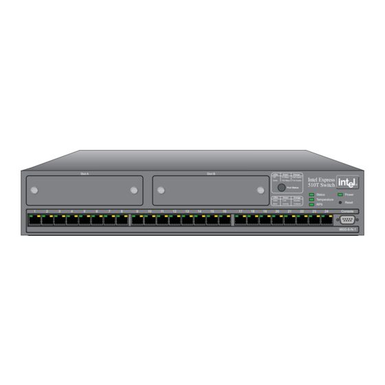
Page 13: Front Panel
Express 510T Switch Front Panel The switch offers the following features: Software features Intel Device View for Windows* 95 and Windows NT* Adaptive forwarding mode Local Management via a direct terminal connection or via TEL- SNMP Management support BOOTP and TFTP support... - Page 14 Express 510T Switch Front Panel The following ports are on the front panel: Front panel ports Port Function CONSOLE port Connects a PC (running a VT100 emula- (DB-9) tion), a VT100 terminal or a modem to access the in-built Local Management pro- gram.
-
Page 15: Rear Panel
Express 510T Switch Rear Panel The buttons on the front panel have the following functions: Buttons Button name Function Port Status To show the operational status of each port. Reset Reset or enter Maintenance Mode Rear Panel The rear panel has a cooling fan outlet and the main supply cable, so... -
Page 16: Installation
Before Installation Unpack the switch carefully and check that all parts are present: Contents of the pack Item Present? One Express 510T Switch One power cord (suitable for your power outlet) One mounting kit One CD-ROM One console cable... -
Page 17: Positioning The Switch
Express 510T Switch Installation It is important that you read the following: Essential reading “Late-Breaking News”. This is packed with the product and contains information you should be aware of when installing and using the product, for example, limitations and compatibility issues. - Page 18 Express 510T Switch Installation The switch is delivered with a kit to attach it to a standard 19-inch Mounting kit equipment rack (with side support rails). The kit contains two mount- ing brackets and four screws (for attaching the brackets to the sides of the switch).
-
Page 19: Installing A Module
Express 510T Switch Installation Set the switch in the equipment rack and ensure there is ade- quate ventilation (see “Allow adequate ventilation” in “Posi- tioning the Switch”, p. 7). Screw the mounting brackets securely to the equipment rack. If the switch is installed in a closed or multi-rack assembly, the oper-... -
Page 20: Connecting Other Devices
Secure it using the retaining screws. If the module does not click into position, refer to the Note Intel Support Web Page (http://support.intel.com) for full instructions on how to install the module success- fully. To remove a module:... - Page 21 Workstation or server Straight-through cable 1:1 Device with MDI-X ports (for exam- Crossover cable ple another Intel switch or hub) Device with MDI ports Straight-through cable 1:1 The 24 RJ-45 ports on the front of the switch have the following pin...
-
Page 22: Connecting The Power
Express 510T Switch Installation Connect one end of the UTP cable to an RJ-45 port on the switch. According to IEEE 802.3, the cable length must not exceed 100 meters (approximately 325 feet). Connect the other end to the 100Base-TX connection on the device. -
Page 23: Power-Up
Express 510T Switch Installation Check that the wire colored brown is connected to the terminal which is marked with the letter L or colored red. If the switch is installed in a rack, ensure the rack’s power supply Power supply to a rack socket has a ground connection and the rack is connected to a branch supply or a power supply socket with a ground connection. - Page 24 Express 510T Switch Installation Look at the other front panel LEDs during start-up and check that they are operating correctly. The LEDs reflect the state of each port: Port LED states Green Orange Shows Port enabled, no link. Blinking Port enabled, Rx/Tx traffic, link pulse randomly active.
-
Page 25: Other Leds On The Front Panel
Express 510T Switch Installation All ports, IP addresses and MAC addresses are in the same VLAN (named <System>). VLANs allow you to create virtual networks using specific switch ports, IP addresses and MAC addresses. Local Management time-out after 10 minutes. -
Page 26: Restoring The Software
Express 510T Switch Restoring the Software Color Meaning Temperature Green Normal operating temperature. Orange Temperature is higher than normal. Check the area around the air intakes and vents are clear of obstructions. Temperature is too high and the switch will shut down Green Off: No RPS connected. - Page 27 Express 510T Switch Restoring the Software You can restore the switch’s software and retrieve log files for Files suitable for TFTP analysis using TFTP. There are various files suitable for TFTP trans- transfer fer: Type Name Contains ASCII report Information for Customer Support staff...
-
Page 28: Recovering From Start-Up Failure
Express 510T Switch Recovering from Start-up Failure Recovering from Start-up Failure The network boot process is as follows: Network boot process 1. The switch sends a BOOTP request over the network. Boot Switch Server (TFTP) Intel Express 510T Switch Boot Request 1302 The boot request contains the switch’s MAC address. -
Page 29: Using Maintenance Mode
Express 510T Switch Recovering from Start-up Failure Using Maintenance Mode Maintenance Mode offers three facilities: Purpose It allows you to force the switch to load a specified software file from any specified TFTP server. It provides an emergency facility to force boot the switch from a specified boot server if the switch cannot boot from Flash Mem- ory. - Page 30 :bf=/intel/switch/es510T_x.xx: This will instruct the switch to load the switch software from the bootp/tftp server. You should use the Intel Device View application to configure the switch manually, or transfer the inxxxxxx.p file con- taining the configuration from a TFTP server to the switch.
-
Page 31: Intel Device View
Chapter 2 Intel Device View This chapter covers the following topics: In this chapter Installation and Uninstallation Using Intel Device View Device View (Main Display) Explorer Trap Window System Window Errors Window... -
Page 32: Installation And Uninstallation
Intel Device View Installation and Uninstallation Installation and Uninstallation You need a PC with the following requirements to run Intel Device Requirements View for Windows: An Intel486™ microprocessor or Pentium® processor (recom- mended). A minimum of 8Mbytes RAM (16Mbytes or more is recom- mended). -
Page 33: Installation Under Windows Nt 4.0 And Windows 95
2. all other int_????.mibs. Installation Under Windows NT 4.0 and Windows 95 To install Intel Device View Switch from the CD ROM under Win- To install Intel Device View dows NT 4.0 or Windows 95, use... -
Page 34: Uninstallation Of Intel Device View For Windows
To uninstall Intel Device View under Windows NT 4.0 or Windows Uninstall under Windows 95, proceed as follows: NT 4.0 or Windows 95 Make sure that you have exited from all Intel Device View pro- grams. From within the Windows , open... -
Page 35: Using Intel Device View
Intel Device View Using Intel Device View Using Intel Device View Intel Device View is used to configure all the parameters on your Concept switch (via SNMP) and monitor switch activity. The tool used for this purpose is called the Switch Manager; see picture below. - Page 36 Click the checkbox in the > window File Open This will allow you to manage the switch in a new Intel Device View window. Click the To add additional new switches (which have not been assigned an IP Adding new switches address) to Intel Device View, select the New Device icon (or select >...
-
Page 37: Device View (Main Display)
You will also need to assign an IP address (and subnet mask) to the switch on your Local Area Network (LAN). This address is used by Intel Device View for configuration and management purposes. Device View (Main Display) When Intel Device View contacts the switch,... - Page 38 Color coding Color Means Grey The switch is operational (the software is loaded and running) and it can be contacted by Intel Device View via the network Black That port or the switch is selected for further work Blue Intel Device View has lost contact with the switch...
-
Page 39: Setting The Preferences
Intel Device View. Setting the Preferences The polling intervals determine how often Intel Device View contacts Setting the polling the switch and updates the status and information displayed. To... - Page 40 Intel Device View Device View (Main Display) The timeout intervals for SNMP determines how often Intel Device Setting the timeout View contacts the monitor and updates the status and information dis- parameters for SNMP played. To change the polling parameters: Select Monitoring>Preferences...
-
Page 41: Menu And Toolbar Overview
Command Action Installs a new switch (which does not have an IP address) in Intel Device View. A switch can also be installed by pressing the New Device Wizard icon Open Opens Intel Device View for a switch which has an IP address. - Page 42 Intel Device View—can also be accessed by selecting the About icon . Context sensitive help is available by select- ing the Help icon then clicking on the feature of interest a color coding chart for the Intel Device View to show the states of switch’s LEDs...
-
Page 43: Explorer
Reference Manual icon Explorer The Explorer within Intel Device View allows you to display man- Intel Device View Explorer agement information, for example VLANs on the switch. If a switch is disabled or not operational, it is displayed with a red cross through it. -
Page 44: System Window
Intel Device View System Window System Window The System window is a log of all the major switch events with date System window and times (for example, return to factory default, filter entry settings, modules inserted in slots). Errors Window... -
Page 45: Standard Configuration
Chapter 3 Standard Configuration Configuration is the way we change the setup of the switch. In this In this chapter chapter you will find all the instructions you need to change setups that affect the switch and the ports. Changing the Setup of the Switch Changing the Setup of the Port In chapter 4 you will find instructions to integrate VLANs into your setup. -
Page 46: Changing The Setup Of The Switch
Standard Configuration Changing the Setup of the Switch Changing the Setup of the Switch To restrict the use of the switch using , you can: Improving switch security Device Setup Change the administrator password. Change the user password. Limit access to Local Management via the port and/or Console Telnet. -
Page 47: System
Standard Configuration Changing the Setup of the Switch System To assist with switch identification and administration, you can Identifying the switch change certain switch details (name, location and contact person): Select Configuration>Device Setup Click System Change the details. Click These details are used by SNMP management centers. -
Page 48: Switching
Standard Configuration Changing the Setup of the Switch Switching To change the time a MAC address is kept in the database before be- Changing the MAC ing purged: address ageing time Select Configuration>Device Setup Click Switching Click MAC Address Ageing Type the required number of minutes. -
Page 49: Adaptive Forwarding Mode
Standard Configuration Changing the Setup of the Switch Click the default forwarding mode you want. Click Adaptive Forwarding Mode You can: Purpose Change the Sample Time Define the minimum and maximum errors before changing adap- tive forwarding mode While CRC errors and runts are the most likely parameters Note to cause the switching mode to change, they are not the only ones. -
Page 50: Internet Protocol
Standard Configuration Changing the Setup of the Switch Adaptive forwarding changes the forwarding mode depending on the Changing number of upper and lower limits of specific error types. To change the number errors before adaptive of upper and lower limits: forwarding mode operates Select Configuration>Device Setup... -
Page 51: Spanning Tree
Spanning Tree and VLANs. The Spanning Tree can use alternative VLANs paths (such as different ports) to get messages to their destination. VLANs specify which ports can receive messages. VLAN Intel Express 10 Switch Intel Express 10 Switch Switch 1 Intel Express 10 Switch Intel Express 10 Switch... - Page 52 Standard Configuration Changing the Setup of the Switch The higher the value, the lower the chance of the switch being used Changing the spanning as the root bridge. To change the priority value: tree priority Select Configuration>Device Setup Click Spanning Tree Click Priority Type the required value.
-
Page 53: Authentication
Standard Configuration Changing the Setup of the Switch Click To change the time between port states while the bridge attempts to Changing the forward become the root: delay expiry time Select Configuration>Device Setup Click Spanning Tree Click Forward Delay Timer Expiry Type the required number of seconds. - Page 54 Standard Configuration Changing the Setup of the Switch The authentications list defines the hosts that can carry out SNMP, Security TFTP or Telnet management on the switch, have read-write or read only rights and access to communities. You can: Add a new entry to the list Delete an entry Edit existing entries To add a host that is allowed to carry out SNMP management on the...
-
Page 55: Traps
Standard Configuration Changing the Setup of the Switch Click , type the SNMP request name accepted by Community the SNMP agent. If no community name is specified, all community names are accepted by the SNMP agent. Click Traps A trap alerts you of the changes that occur in the SNMP agent system. Purpose The traps list shows where SNMP traps (generated by the switch) are sent. -
Page 56: Local Time
Standard Configuration Changing the Setup of the Switch Local Time To change the clock in the switch to your local time: Setting the date and clock to local time Select Configuration>Device Setup Click Date/Time Click to show the present Insert Current PC Date/Time settings. -
Page 57: Local Management
Standard Configuration Changing the Setup of the Switch Local Management The administrator has read-write access at all levels. The user can Changing password read the monitoring screens, but is not allowed to change the config- details uration, update software or reset the station. To prevent unauthorized personnel changing configurations. -
Page 58: Tftp
Standard Configuration Changing the Setup of the Port TFTP To give added security, you can limit the number of staff authorized Changing password to transfer TFTP files by changing the TFTP password. To change the details password. Select Configuration>Device Setup Click TFTP Type the old password. -
Page 59: General Changes
Standard Configuration Changing the Setup of the Port General Changes To give a port a new name, for example, its use or the user(s) connect- Renaming a port Click the port you want to rename. Select Configuration>Port Setup Click General Click in the field. -
Page 60: Port Mode
Standard Configuration Changing the Setup of the Port Port Mode If you disable the port, the devices attached to it cannot use the Disabling the port switch. The MAC address of those devices are removed from the switch’s address table after the MAC address ageing time has elapsed. - Page 61 Standard Configuration Changing the Setup of the Port Click Enable Auto-negotiation If there is a check mark is in the box, the port automatically detects the line-speed and duplexity. If the box is empty, auto- negotiation is disabled and the port uses the values specified in Duplex Speed Click...
-
Page 62: Port Specific Spanning Tree
Standard Configuration Changing the Setup of the Port Click the forwarding mode you want. is the same forwarding mode as specified in Default Con- figuration>Device Setup. Click Flow control prevents the loss of frames during busy periods. To Changing the flow control change the flow mechanism on a port: on a port Click the port you want to change. - Page 63 Standard Configuration Changing the Setup of the Port Click Spanning Tree Click Enable spanning tree on this port If there is a check mark in the box, the port is used in STP. If the box is empty, the port is not used in STP. Click The higher the cost, the lower the chance of this port being used in Changing the cost of the...
- Page 64 Standard Configuration Changing the Setup of the Port Type the required value. If there are two ports with the same value, the port with the lowest port number will be chosen. Click...
-
Page 65: Advanced Configuration
Chapter 4 Advanced Configuration In this chapter you will learn how to use Advanced Configuration ef- In this chapter fectively. This chapter covers VLANs (Virtual LANs). Create logical network groups (Virtual LANs) by segmenting the switch, for example according to the subnetting scheme within your network. -
Page 66: Vlans (Virtual Lans)
Advanced Configuration VLANs (Virtual LANs) VLANs (Virtual LANs) The use of VLANs lets you: Purpose Create up to 128 separate user groups Limit broadcast and multicast traffic Increase security by limiting communication between groups Allocate network resources (such as servers) to groups For a more comprehensive explanation of the VLAN concept, refer to the online help. - Page 67 Advanced Configuration VLANs (Virtual LANs) This task of adding VLANs is simplified by using the Adding a VLAN VLAN Wizard To add a VLAN: Select Configuration>VLAN Setup Click , and follow the instructions in the Wizard windows. Policy Information required Switch Ports Port numbers IP Subnet...
- Page 68 Advanced Configuration VLANs (Virtual LANs) To change the name of a VLAN: Changing the name of a VLAN Select Configuration>VLAN Setup Click the name of the VLAN you want to delete. Click The VLAN name is highlighted. Properties... Type the new name VLAN Name Click to accept the name.
-
Page 69: Managing The Switch
Chapter 5 Managing the Switch This chapter covers the following topics. In this chapter Monitoring the Switch’s Performance Monitoring the Port’s Performance Tools for the Switch... -
Page 70: Management Using Intel Device View
Managing the Switch Management using Intel Device View Management using Intel Device View Intel Device View allows you to: Why use Intel Device View? Use the Switch Manager to: - Configure system, switching, IP, spanning tree, authentica- tion, and trap parameters for the switch. -
Page 71: Monitoring The Switch's Performance
Managing the Switch Management using Intel Device View Monitoring the Switch’s Performance To view the total activity of the packets on all the ports: Monitoring the total packet activity Select Monitoring>Device Activity>Total Pack- ets... Each column represents a port and its activity level. - Page 72 Managing the Switch Management using Intel Device View To view the total activity of the packets being received on all the Monitoring the total ports: activity of received packets Select Monitoring>Device Activity>Rx Packets... Each column represents the activity level on that port.
- Page 73 Managing the Switch Management using Intel Device View To view the setups of all the ports on the switch: Overview of all the ports Select Monitoring>Port Overview... Double-click a port to get the specific details on: port perfor- mance, faults, packet distribution and spanning tree information...
- Page 74 Managing the Switch Management using Intel Device View To view the VLANs on the switch: Overview of the VLANs Select Monitoring>VLAN Monitoring... This shows a full list of VLANs active on the switch. This win- dow is also viewed from the Explorer by right-clicking the VLAN name and selecting Monitor...
-
Page 75: Monitoring The Port's Performance
Managing the Switch Management using Intel Device View Monitoring the Port’s Performance On the Switch Manager’s picture of the switch, the different colors on Using the LEDs the ports indicate the different states of activity. Select Help>Dis- for further information on LED states. - Page 76 Managing the Switch Management using Intel Device View To change the display from numerical to graphical, click on one or more of the numbers and select Tools>Graph Select to set all these counters to Options>Reset Counters zero. To monitor the faults on a specific port:...
- Page 77 Managing the Switch Management using Intel Device View To monitor the received packets on a specific port: Monitoring the received packets on a port Click the port. Select Monitoring>Port Activity...>RX... Packets Select , followed by View>Stop Collection File>Print print the graph.
-
Page 78: Tools For The Switch
Managing the Switch Management using Intel Device View To view the VLANs on the port: Monitoring the VLANs on a port Select Monitoring>VLAN Port Monitoring... Click on either of the tabs to view details of that port: Double-click a row to Tab Name: Shows the VLAN’s... -
Page 79: Report Manager
Managing the Switch Management using Intel Device View Report Manager To view a log or report: Using the Report Manager Select Tools>Report Manager Double-click , and type the correct IP address for IP Address the device you want to receive the directory. - Page 80 Managing the Switch Management using Intel Device View To access the probe in the switch, click the icon on Find a probe on the switch RMON Manager the tool bar of the Switch Manager. The main window of the RMON Manager contains the following...
- Page 81 Managing the Switch Management using Intel Device View To access a wider range of subnet management statistics: Further interface statistics 1. Right-click the interface icon in the window. This opens Probe the interface popup menu. 2. Select . This window gives more detailed informa- Statistics tion about the subnet in the form of counters.
-
Page 82: Local Management
Managing the Switch Management using Intel Device View The RMON Manager can also be started from the command line: Command line startup 1. Open a command prompt. 2. At the prompt you can enter the following commands: RMONMGR [IP= [COMM= <IP address>]... - Page 83 Managing the Switch Management using Intel Device View The switch’s ASICs (Application-Specific Integrated Circuits) and What does it do? support for RMON provide complete management without compro- mising the switch’s performance. The management facility is divided into four parts: Configuration Allows you to change the basic configuration parameters of the...
- Page 84 Managing the Switch Management using Intel Device View Instructions on how to access the application have been mentioned Access to the Local earlier: Management application Access from the port CONSOLE Details are in Quick Start. Access using Telnet Select Tools>Local Management...
-
Page 85: Technical Specifications
Chapter 6 Technical Specifications This chapter covers the following topics. In this chapter Physical Specifications Power Specifications Performance Specifications Module Specifications... -
Page 86: Physical Specifications
Technical Specifications Physical Specifications Physical Specifications The switch has the following approvals: Approvals Approval for Standard Safety UL 1950, CSA-C22.2 No. 950, IEC 950, EN 60950 Emission FCC 47 CFR part 15 Class A, EN 55022 Class A, CISPR 22 Class A VCCI Class 1 ITE “C-Tick”... - Page 87 Technical Specifications Physical Specifications The switch has the following environmental specifications: Environmental Operating temperature +41 ˚F to +104 ˚F (+5 ˚C to +40 ˚C) Storage temperature –13 ˚F to +158 ˚F (–25 ˚C to +70 ˚C) Humidity Less than 85% non-condensing Altitude 10000 feet (3048 meters) The switch has the following number of LEDs:...
-
Page 88: Power Specifications
Technical Specifications Power Specifications Power Specifications Power consumption: 100W maximum Consumption The power supply has: Power supply Nominal power supply 100 to 120 V AC, 2.5 A voltages 200 to 240 V AC, 1.5 A Class 1 protective ground Voltage range 90 to 135 V 180 to 265 V Frequency... - Page 89 Technical Specifications Performance Specifications The memory sizes are as follows: Memory sizes Memory Express 510T Switch Flash Memory (Mbytes) DRAM (Mbytes) Buffer RAM (Mbytes) CPU RAM (Mbytes) This switch supports the following protocols: Supported protocols Subject Document Reference Bridge/Spanning Tree IEEE 802.1D...
-
Page 90: Module Specifications
RMON RFC 1757 Module Specifications There are two modules for this switch: Range Media Module Name Intel Order Code 10/100TX Module for 500 Series Switches ES500MTX 100FX Module for 500 Series Switches ES500MFX The modules have the following physical specifications:... -
Page 91: Troubleshooting
Chapter 7 Troubleshooting This chapter covers the following topics. In this chapter Troubleshooting Tools Troubleshooting Procedure Typical Problems and Causes Reporting Problems to Intel Customer Support... -
Page 92: Troubleshooting Tools
Troubleshooting Troubleshooting Tools Troubleshooting Tools The tools available for troubleshooting on the switch are: Troubleshooting tools available The LED indicators These are provided on the front panel of the switch. The LEDs indi- cate the overall switch status, and the status of each of the switch’s ports and backplane segments (where applicable). -
Page 93: Further Evaluation Of The Problem
Troubleshooting Typical Problems and Causes unexpected events and configuration errors. The System Log reports such things as software successfully located and loaded, ports enabled or disabled, and if any SNMP traps have been sent. Further Evaluation of the Problem If you still cannot resolve the problem satisfactorily from the infor- If the problem is still not mation gained in the previous procedure, access the Monitor within isolated... - Page 94 Troubleshooting Typical Problems and Causes When I make changes to the switch’s configuration, they take effect but as soon as the switch is powered off and on again the changes are lost When you change the switch’s configuration, you are Explanation: changing the current active configuration that is running in RAM.
-
Page 95: Performance Problems
Troubleshooting Typical Problems and Causes Performance Problems One or more workstations cannot communicate with a server or other device through the switch This symptom might be noticed on one or more seg- Explanation: ments connected to the switch, and could be caused by cable faults, inappropriate configuration or faulty installation. -
Page 96: Reporting The Problem To Intel Customer Support
If you are unable to solve the problem and want to report the problem Introduction to Intel Customer Support, there are certain things that you can do, to enable us to begin solving your problem quickly. Intel Device View makes the gathering of such information easy, and presents it in an easy-to-interpret format. - Page 97 The information in this report can be of great help to us in finding a solution to the problem as quickly as possible. For information about Intel’s automated support service and how to Further information on contact our technical support technicians, see the information on the Customer Support page inside the back cover.
- Page 98 Troubleshooting Reporting the Problem to Intel Customer Support...
-
Page 99: Limited Hardware Warranty
(RMA) number either to the company from whom you purchased it or to Intel (North America only). If you ship the product, you must assume the risk of damage or loss in transit. -
Page 100: Limited Hardware Warranty (Europe Only)
(RMA) number either to the company from whom you purchased it or to Intel. If you ship the product, you must assume the risk of damage or loss in transit. - Page 101 Limited Hardware Warranty Limited Hardware Warranty (Europe only) Some states do not allow the exclusion or limitation of incidental or consequential damages, so the above limitations or exclusions may not apply to you. Software provided with the hardware product is not covered under the hardware warranty described above. See the applicable soft- ware license agreement which shipped with the hardware product for details on any software warranty.
-
Page 102: Federal Communications Commission (Fcc) Statement
Manufacturer Declaration Intel declares that the Express 500 Series Switches comply with the EU Directive 89/336/EEC, using the EMC standards EN55022 and EN50082-1. These products also meet EU Directives 74/23/EEC and 93/68/ and are certified by DEMKO to be compliant with EN 60950/A1/A2/A3 and by UL to be compliant with UL 1950 and CSA -C22.2 No. -
Page 103: Warnung
Limited Hardware Warranty WARNUNG Dans les régions sujettes aux orages magnétiques il est recomandé de brancher votre système à un supresseur de surtension, et de débrancher toutes les lignes de télécommunications de votre modem durant un orage. Muni d’une prise murale correctement mise à la terre. Ne pas utiliser ni modifier le câble d’alimentation C. -
Page 104: A Limited Hardware Warranty
Limited Hardware Warranty ADVERTENCIAS Bien ventilado y alejado de fuentes de calor, incluida la luz solar directa. Alejado de fuentes de vibración. Aislado de campos electromagnéticos fuertes producidos por dispositivos eléctricos. En regiones con frecuentes tormentas eléctricas, se recomienda conectar su sistema a un eliminador de sobrevoltage y desconectar el módem de las líneas de telecomunicación durante las tormentas. -
Page 105: Network Software License Agreement
OWNERSHIP AND COPYRIGHT OF SOFTWARE: Title to the Software and all copies thereof re- main with Intel or its vendors. The Software is copyrighted and is protected by United States and inter- national copyright laws. You will not remove the copyright notice from the Software. You agree to prevent any unauthorized copying of the Software. - Page 106 AUDIT: Intel reserves the right to have audits conducted to verify your compliance with this Agreement. TERMINATION OF THIS LICENSE: Intel may terminate this license at any time if you are in breach of any of its terms and conditions. Upon termination, you will immediately destroy the Software or return all copies of the Software and documentation to Intel.
-
Page 107: Garantie Matérielle Limitée
Si le produit est malgré tout défectueux, Intel se réserve le droit de remplacer ou de réparer le produit sans frais supplé- mentaires, sauf dans les cas définis ci-dessous, et à condition que vous renvoyiez le numéro d’autorisation de renvoi de matériel à... -
Page 108: Avis De La Commission Fédérale Américaine À La Communication (Fcc, Federal Communications Commission)
Avis du fabricant Intel certifie que Intel Express 500 Series Switches se conforme à la norme européenne 89/33/EEC, et suit le standard EMC EN55022 (classe A) et EN50082-1. Ce produit est également conforme ou dépasse la norme exigée EN 60950 (TUV). Ce produit a été... -
Page 109: Garanzia Limitata Per L'hardware
L'acquirente deve usare l'imbal- laggio originale (o equivalente) e pagare le spese di spedizione. Intel potrà sostituire o riparare il prodotto con un prodotto o parti nuovi o ricondizionati. -
Page 110: Avviso Fcc
Dichiarazione del fabbricante Questo documento attesta che Intel Express 500 Series Switches è conforme all Direttiva CEE UE 89/33, usando gli standard EMC EN55022 (Classe A) e EN50082-1. Questo prodotto soddisfa o supera inoltre i requisiti EN 60950 (TUV). Questo prodotto è stato sottoposto a prova e verificato secondo i requisiti CISPR 22, Classe A. -
Page 111: Beschränkte Hardware-Garantie
Sie liefern das Produkt zusammen mit einer RMA (Materialrückgabegenehmigung)-Nummer an die Fir- ma, bei der Sie es erworben haben, oder an Intel (nur in Nordamerika). Wenn Sie das Produkt senden, müssen Sie das Transpor- trisiko bezüglich Schäden oder Verlust selbst übernehmen. Sie müssen den Originalbehälter (oder dessen Äquivalent) verwenden und die Transportkosten tragen. -
Page 112: Erklärung Der Federal Communications Commision (Fcc)
Herstellers Änderungen und Modifizierungen am Gerät vornimmt. Erklärung des Herstellers Wir bestätigen hiermit, daß der Intel Express 500 Series Switches die Anforderungen der EU-Richtlinie 89/33/EEC erfüllt und den EMC-Standards EN55022 (Klasse A) und EN50082-1 entspricht. Außerdem erfüllt oder übertrifft dieses Produkt die Anforderun- gen gemäß... -
Page 113: Garantía Limitada Del Hardware
éste ocurra dentro de 30 días después de la compra. Esta ga- rantía no cubre el producto si se daña en el proceso de ser instalado. Intel recomienda pedir a la empresa a la cual compre este producto que lo instale. -
Page 114: Declaración De La Comisión Federal De Comunicaciones (Fcc)
Declaración del fabricante Se certifica que el Concentrador apilable Intel Express 500 Series Switches la Directiva EU 89/33/EEC, utilizando las normas EMC EN55022 (Clase A) y EN50082-1 de EMC. Este producto también cumple o excede los requisitos de la EN 60950 (TUV). Este producto ha sido probado y verificado para cumplir con los requisitos CISPR 22 Clase A. - Page 115 Limited Hardware Warranty Garantía limitada del hardware...
- Page 116 Limited Hardware Warranty Garantía limitada del hardware...
- Page 117 Limited Hardware Warranty Garantía limitada del hardware...
- Page 118 Limited Hardware Warranty Garantía limitada del hardware...
- Page 119 Index Index Numerics 10/100Base-TX port ........ 4 Bootload using maintenance mode ..19 Button functions ........5 Access restrictions to Local Management ... 14 Cable to Local Management ...... 74 for the Console Port ......11 Access to SNMP ........43 for the LAN Ports ......
- Page 120 ........35 Essential reading ........7 Connect other devices ........10 power ..........12 Connection Facilities, Intel Device View ....28 main power ........5 Fan ............5 redundant power supply ....5 Files Connections, number of ....77 , 80 suitable for TFTP transfer ....
- Page 121 ........... 73 on a desktop ........7 Location for a port ......... 49 requirements ........ 6 , 22 under LANDesk Network Manager 22 Intel Device View MAC addresses alarms, RMON ......... 71 ageing time ........14 concept ..........25 change ageing time ......
- Page 122 Index removal ..........10 Performance problems, troubleshooting ..weight ..........80 Memory sizes ........79 Physical features ........2 Message age expiry time, change ..42 Policy-based VLANs ......56 Missing parts ........... 6 Port Monitor 10/100Base-TX ........4 distribution of frames on a port ..66 CONSOLE .........
- Page 123 ..........49 Status LED ..........15 Report Manager ........25 Storage temperature ......77 Report Manager, Intel Device View ..69 Requirements change cost of the path ....53 for the rack .......... 7 change priority of the port ....53 installation ........
- Page 124 Index ventilation .......... 7 Switch Manager in Intel Device View Ventilation ..........7 VLAN add ............. 57 change name ........58 TCP/IP ........... 22 delete ..........57 TELNET ..........25 overview ........56 , 64 Temperature LED ......... 15 policy hierarchy ....... 56 TFTP policy-based ........
- Page 125 Index...
- Page 126 Intel Automated Customer Support You can reach Intel's automated support services 24 hours a day, every day at no charge. The services contain the most up-to-date information about Intel products. You can access installation instructions, troubleshooting information, and general product information.
Need help?
Do you have a question about the Express 510T and is the answer not in the manual?
Questions and answers