Table of Contents
Advertisement
Quick Links
This service information is designed for experienced repair technicians only and is not designed for use by the general public. It does not contain
warnings or cautions to advise non-technical individuals of potential dangers in attempting to service a product.
Products powered by electricity should be serviced or repaired only by experienced professional technicians. Any attempt to service or repair the
product or products dealt with in this service manual by anyone else could result in serious injury or death.
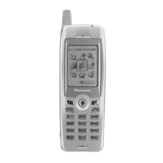
EB-GD95
EB-GD95C
Frequency Range
Tx/Rx frequency
separation
RF Channel Bandwidth
Number of RF channels
Speech coding
Operating temperature
Type
RF Output Power
Modulation
Connection
Voice digitizing
Transmission speed
Diversity
Signal Reception
Antenna Terminal
Impedance
Antenna VSWR
Dimensions
(excluding antenna)
Volume
Weight
Display
Illumination
Keys
SIM
External DC Supply
Voltage
Battery
Standby Time
Talk Time
Battery life figures are dependent on battery and network conditions, SIM card and usage.
WARNING
© 2001 Matsushita Communication Industrial UK Ltd.
All rights reserved. Unauthorized copying and
distribution is a violation of law.
Order Number: MCUK010801C8
Personal Cellular Phone
900 MHz
Tx: 880 - 915MHz
Tx: 1710 -1785 MHz
Rx: 925 - 960 MHz
Rx: 1805 -1880 MHz
45 MHz
95 MHz
200 kHz
174
374
Full rate/Half rate/Enhanced Full rate
-10 °C to +55 °C
Class 4 Handheld
Class 1 Handheld
2 W maximum
1 W maximum
GMSK (BT = 0.3)
8 ch / TDMA
13 kbps RPE-LTP / 13 kps ACLEP / 5.6 kps CELP / VSLEP
270.833 kbps
Frequency hopping
Direct conversion
50 τ
< 2.1 : 1
Height: 125.5 mm
Width:
45.5 mm
Depth:
14.3 mm
90 cc
85 g
Graphical chip on glass liquid crystal, Alphanumeric,
16 characters x 3 rows + 2 lines of icons.
4 LEDs for the LCD
8 LEDs for the keypad (Green)
1 LED Incoming call (Green)
1 Charging LED (Red)
18-key Keypad, Navigation key.
Plug-in type only
5.8 V
3.7 V nominal, 650mAh, Li-Ion
150 hrs maximum
270 minutes maximum
1800 MHz
Advertisement
Table of Contents

Related Manuals for Panasonic GSM EB-GD95


Summary of Contents for Panasonic GSM EB-GD95
- Page 1 Order Number: MCUK010801C8 Personal Cellular Phone EB-GD95 EB-GD95C 1800 MHz 900 MHz Frequency Range Tx: 880 - 915MHz Tx: 1710 -1785 MHz Rx: 925 - 960 MHz Rx: 1805 -1880 MHz Tx/Rx frequency 45 MHz 95 MHz separation RF Channel Bandwidth 200 kHz Number of RF channels Speech coding...
- Page 2 Every care has been taken to ensure that the contents of this manual give an accurate representation of the equipment. However, Matsushita Communication Industrial UK Ltd. accepts no responsibility for inaccuracies which may occur and reserves the right to make changes to the specification or design without prior notice. The information contained in this manual and all rights in any design disclosed therein, are and remain the exclusive property of Matsushita Communication Industrial UK Ltd.
-
Page 3: Table Of Contents
CONTENTS 1 INTRODUCTION Purpose of this Manual ......1 Structure of the Manual ......1 Servicing Responsibilities . - Page 4 This page is left intentionally blank. Issue 1 Section MCUK010801C8 Revision 0 – iv – Service Manual...
-
Page 5: Introduction
They must not be incinerated, or disposed of as ordinary rubbish. 1.1. Purpose of the Manual This Service Manual contains the information and procedures required for installing, operating and servicing the Panasonic GSM Personal Cellular Mobile Telephone system operating on GSM Digital Cellular Networks. -
Page 6: General Description
2.2. Features Panasonic Telephone Models GD95 and GD95C are high performance, small, light, handsets for business and domestic use. The following features are provided: Triple Rate, which includes Full Rate, Half rate and Enhanced Full Rate (EFR) speech, codec. -
Page 7: Operating Instructions
OPERATING INSTRUCTIONS 3 OPERATING INSTRUCTIONS 3.1. General This section provides a brief guide to the operation and facilities available on the telephone handset. Refer to the Operating Instructions supplied with the telephone for full operational information. 3.2. Liquid Crystal Display The telephone handset has a graphical chip on glass display. -
Page 8: Location Of Controls
OPERATING INSTRUCTIONS 3.3. Location of Controls Incoming / Charge indicator: Green - Incoming call. Red - Charging battery pack. External connector: Used to connect to external accessories or to charging equipment. INCOMING CALL / EARPIECE CHARGE INDICATOR ANTENNA EXTERNAL DISPLAY ANTENNA CONNECTOR NAVIGATION KEY... -
Page 9: Concept Of Operation
OPERATING INSTRUCTIONS 3.4. Concept of Operation There is a close relationship between the Select keys, Navigation key and display. Secondary Main Option Area Option Area Select Key Select Key Navigation 10405-1 Figure 3.3: Concept of Operation Pressing up and down ( ) will move the pointer up and down and scroll through more information in the main area of the display. -
Page 10: Features Menu Structure
OPERATING INSTRUCTIONS 3.5.2 Editing Alpha Entry Pressing will move the cursor up or down one line. Pressing will move the cursor left or right one character. When the cursor is moved over a character and another key pressed this will insert the new character. Pressing will delete the character to the left of the cursor. -
Page 11: Incoming Call Line Identification (Cli)
OPERATING INSTRUCTIONS 3.7.Incoming Call Line Identification (CLI) When a call is received the last six digits of the CLI information is matched with the phonebook. Therefore an incoming call could be matched to the wrong phonebook entry. 3.8. Hot Key Dial Source List The source for Hot Key Dial Numbers is normally ‘Phonebook’... -
Page 12: Calling Line Identification
OPERATING INSTRUCTIONS 3.9.7 Calling Line Identification Feature Service Code Calling Line Identification Presentation (CLIP) Calling Line Identification Restriction (CLIR) Connected Line Presentation (CLOP) Connected Line Restriction (CLOR) Enable * <SERVICE CODE> * # <SND> Disable # <SERVICE CODE> * # <SND> Temporary Suppress Identification # 3 1 # <TELEPHONE NUMBER>... -
Page 13: Call Divert
OPERATING INSTRUCTIONS 3.9.9 Call Divert Call Divert Type Service Code Divert all calls Divert all calls if busy Divert calls if no reply Divert if not reachable Set (except “No Reply” Call * * <SERVICE CODE> * <FORWARD TELEPHONE NUMBER> * <TELECOMMUNICATION SERVICE>... -
Page 14: Troubleshooting
OPERATING INSTRUCTIONS 3.10. Troubleshooting The user is given the following information and advised to contact the dealer if the problems persist: Problem Cause Remedy Telephone will not switch Check that the battery pack is fully charged and correctly connected to the telephone. Extremely short battery The network in use and the condition of the Avoid areas of poor reception. -
Page 15: Important Error Messages
OPERATING INSTRUCTIONS 3.11. Important Error Messages The following table is a list of error messages that may occur during use of the telephone, with a description and suggested course of action: Error Message Explanation / Remedy Area not Allowed Roaming in the selected area is not allowed. Network not Allowed Roaming with the selected network is not allowed. -
Page 16: Sim Personalisation
OPERATING INSTRUCTIONS 3.13. SIM Personalisation 3.13.1 Introduction SIM personalisation will limit the use of the telephone to a single SIM, a SIM supplied by one Network/Sub-network/Service Provider or a SIM purchased by a company (corporation). If a personalised handset contains a SIM that is from a different source, it will display the message “SIM ERROR”... -
Page 17: Gsm Services Supported By Pc Card
OPERATING INSTRUCTIONS 3.13.5 Enabling Procedure to point at: “SIM” for SIM Personalisation ”Network” for Network Personalisation “Subnetwork” for Subnetwork Personalisation ”SP” for Service Provider Personalisation or ”Corporate” for Company Personalisation. the 16 digit Control Key. the 16 digit Control Key. The display will confirm which type of Personalisation has been enabled. -
Page 18: Gsm Network Codes And Names
OPERATING INSTRUCTIONS 3.15. GSM Network Codes and Names Access Network Service or Operator Phone Display Band Code Code ALBANIA +355 AMC MOBIL AMC - AL GSM 900 ANDORRA +376 MOBILAND STA-MOBILAND GSM 900 ARMENIA +374 ARMGSM RA-ARMGSM GSM 900 AUSTRALIA MOBILENET TELSTRA GSM 900... - Page 19 OPERATING INSTRUCTIONS Access Network Service or Operator Phone Display Band Code Code HONG_KONG +852 HK SMC HK SMC GSM 900 HK TELECOM CAMPERSANDW HKT GSM 900 NEW WORLD NEW WORLD GSM 1800 Orange Orange GSM 900 P Plus P Plus GSM 1800 P-Link P-Link...
- Page 20 OPERATING INSTRUCTIONS Access Network Service or Operator Phone Display Band Code Code MOROCCO +212 ONPTGSM MOR ONPT GSM GSM 900 NAMIBIA +264 NAM MTC GSM 900 NETHERLANDS Ben NL Ben NL GSM 1800 KPN TELECOM NL KPN TELECOM GSM 900 LIBERTEL NL LIBERTEL GSM 900...
- Page 21 OPERATING INSTRUCTIONS Access Network Service or Operator Phone Display Band Code Code TAIWAN +886 Chunghwa Chunghwa GSM 900 Far EasTone Far EasTone GSM 900 KGT-ONLINE KGT-ONLINE GSM 1800 ROC MOBITAI MOBITAI GSM 900 TUNTEX TUNTEX GSM 1800 TWN GSM TWN GSM GSM 1800 TransAsia Telecom GSM TransAsia GSM...
-
Page 22: Glossary Of Terms
OPERATING INSTRUCTIONS 3.16. Glossary of Terms Term Definition DTMF Dual Tone Multiple Frequency tones. The numeric keys 0 to 9, and * and # will generate different DTMF tones when pressed during conversation. These are used to access voice mail, paging and home banking services. -
Page 23: Disassembly / Reassembly Instructions
DISASSEMBLY / REASSEMBLY INSTRUCTIONS 4 DISASSEMBLY / REASSEMBLY INSTRUCTIONS General 4.1. This section provides disassembly and reassembly procedures for the main components of the telephone. These assemblies MUST be performed by qualified service personnel at an authorised service centre. The following Warnings and Cautions MUST be observed during all disassembly / reassembly operations: WARNING The equipment described in this manual contains polarised capacitors utilising liquid electrolyte. - Page 24 DISASSEMBLY / REASSEMBLY INSTRUCTIONS Carefully prise apart the case and cover, creating a gap at the base I/O connector. Insert the Case Separation Tool (see Section 6) into the gap created, and gently slide the tool in the direction shown, ensuring that the moulded hooks separate all the way up to point ‘A’.
- Page 25 DISASSEMBLY / REASSEMBLY INSTRUCTIONS 4.2.2 LCD Removal Gently prise apart the two ears of the LCD Retainer (marked ‘A’ and ‘B’ in the diagram below) so that it is released from the PCB. 10463-1 Figure 4.4: LCD Module Removal The LCD assembly can now be removed from the PCB. To remove the LCD, carefully lift the flexible PCB away from the two retaining lugs on the underside of the LCD Holder.
- Page 26 DISASSEMBLY / REASSEMBLY INSTRUCTIONS Remove the microphone assembly by prising upward with a small screwdriver blade or similar blunt object through the slot in the side of the microphone holder. 10474-1 Figure 4.7: Removal of Microphone To remove the speaker, first remove the retaining clip. Then lift the speaker from the case by inserting a small screwdriver blade or similar blunt object underneath it.
-
Page 27: Reassembly
DISASSEMBLY / REASSEMBLY INSTRUCTIONS 1. Lift the DTHF speaker from the case by inserting a small screwdriver blade or similar blunt object underneath it. 10462-1 Figure 4.10: DTHF Speaker Removal The Vibrate motor may be removed from the RF shield by pushing on the underside of the motor body. 10461-1 Figure 4.11: Removal of Vibrate Motor Using a small screwdriver blade or similar blunt object, depress the lug on the antenna base in order to release the entire... -
Page 28: Technical Specifications
TECHNICAL SPECIFICATIONS 5 TECHNICAL SPECIFICATIONS 5.1. Tx Characteristics All data is applicable to E-GSM 900 and GSM 1800 except where stated. 5.1.1 Frequency Error ±0.1 ppm max., relative to base station frequency. 5.1.2 Modulation Phase Error RMS: Equal to or less than 5 ° Peak Equal to or less than 20 °... -
Page 29: Rx Characteristics
TECHNICAL SPECIFICATIONS 5.1.5 Spurious Emissions at Antenna Connector Limits (dBm) Frequency Filter Approx. Frequency Range Offset Bandwidth Video B/W E-GSM 900 GSM 1800 30 to 50 MHz 10 kHz 30 kHz 50 to 500 MHz 100 kHz 300 kHz 500 MHz to 1GHz 0 to 1 MHz 100 kHz 300 kHz... - Page 30 TECHNICAL SPECIFICATIONS E-GSM 900 Half Rate Speech The reference sensitivity performance in terms of frame erasure, bit error, or residual bit error rates (whichever is appropriate) is specified in the following table, according to the propagation conditions. Propogation Conditions Propogation Conditions Propogation Conditions Channels TUhigh...
- Page 31 TECHNICAL SPECIFICATIONS Blocking: Small MS level in dBµVemf() Frequency E-GSM 900 GSM 1800 FR 600 kHz to FR 800 kHz FR 800 kHz to FR 1.6 MHz FR 1.6 MHz to FR 3 MHz 915 MHz to FR -3 MHz FR 3 MHz to FR 980 MHz FR 600 kHz to FR 800 kHz 1785 MHz to FR - 3 MHz...
-
Page 32: Test And Measurement
TEST AND MEASUREMENT 6 TEST AND MEASUREMENT 6.1. Introduction This section provides information on testing the telephone. The layout is as follows: Section 6.2: Handling and repair of Any-Layer Interstitial Via Hole (ALIVH) PCBs. Section 6.3 External testing: describes equipment requirements and general set up procedure. Section 6.4 Complete Unit Test Setup: describes how the items of test equipment are used together and general set up procedure. -
Page 33: External Testing
TEST AND MEASUREMENT Hot-Air Blower The blower air temperature should be at: 295 °C ±5 °C for an application time of 120 seconds or less, 395 °C ±5 °C for an application time of 30 seconds or less. Removal and re-mounting of components should be performed only once at any component position. Note: To avoid land detachment, do NOT apply excessive force on the soldering iron when heating the board. -
Page 34: Power Supply
TEST AND MEASUREMENT 4 . 8 . 2 8 FRONT REAR 10016-1 Figure 6.1: Interface Box IFB003 / IFB004 Personal Computer (PC) The PC (IBM compatible) is used as a Unit Under Test controller. This in conjunction with the channel box software, allows all of the test facilities normally provided through the keypad of the Unit Under Test. - Page 35 TEST AND MEASUREMENT GSM Tester This unit acts as a base station providing all the necessary GSM signalling requirements and also provides GSM signal measuring facilities. Dummy Battery (Part No. JT00069) The dummy battery is used for battery calibration. 10017-1 Figure 6.4: Dummy Battery Channel Box Software This is the test software for the telephone unit and should be installed onto the personal computer to be used for testing.
-
Page 36: Complete Unit Setup
TEST AND MEASUREMENT 6.4. Complete Unit Setup 6.4.1 Connection Diagrams INTERFACE BOX +12V POWER SUPPLY RS232 GSM TESTER PCB REPAIR JIG RF CABLE PCB TEST SETUP INTERFACE BOX +12V POWER SUPPLY RS232 RF ADAPTOR GSM TESTER RF CABLE UNIT UNDER TEST COMPLETE UNIT TEST SETUP 10491-1 Figure 6.6: Test Connection Diagrams... - Page 37 TEST AND MEASUREMENT For testing the handheld unit the following equipment is required: Interface Box IFB003 or IFB004 12 V power supply Personal computer (IBM compatible) with RS232 interface RS232 interface cable (9 pin straight through connection) GSM test station RF Adaptor Interface Cable JT00004 The channel box software (supplied on floppy disk) should be installed onto the main drive of the personal computer.
- Page 38 TEST AND MEASUREMENT Figure 6.8: PC Screen (SCRN10) Press ENTER on the PC keyboard. At the PC press Shift F10. After approximately 1 second, set the ExtPwr switch to ON until the unit powers up. NOTE: The Display will read: GET STATION ADDRESS = __...
- Page 39 TEST AND MEASUREMENT Channel Box software loaded and the screen indication as follows Figure 6.10: PC Screen (SCRN9) On the PC, select NORMAL MODE and press ENTER. Press Shift F10 on the PC. After approximately 1 second, set the ExtPwr switch to ON until the unit powers up. Enter Call Mode from Test Mode Ensure that a fully-charged battery is attached to the telephone.
-
Page 40: Channel Box Test Commands
TEST AND MEASUREMENT 6.5. Channel Box Test Commands The following table outlines the commands available using the channel box software. After the telephone unit has been switched on (Section 6.4), use the up / down cursor keys on the PC keyboard to select the channel box command. -
Page 41: Rf Calibration Procedure
ADJUSTMENT PROCEDURES 7 ADJUSTMENT PROCEDURES 7.1. RF Calibration Procedure NOTE: See Section 6.2 for a list of the equipment and setup procedures required to perform the following adjustment and calibration procedures. The following procedures MUST be performed after replacement or repair of the PCB. Failure to do so may result in incorrect operation of the telephone. - Page 42 7.2.3 Power Level Calibration NOTE: To ensure that the telephone operates within set SAR margins, Panasonic recommends that a power meter capable of measurement to an accuracy of ±0.2 dB is used when calibrating power levels. Use of a less accurate power meter may result in the telephone failing to meet SAR standards.
- Page 43 ADJUSTMENT PROCEDURES At the Channel box, press F7 to view the TRIM for the mid-channel. Select VIEW TRIM PL MCH, and make a note of this value. Perform the following calculation and make a note of the result: New Trim Value = Old TrimValue + (Required Power - Measured Power) x Change per dB (step 5)
- Page 44 ADJUSTMENT PROCEDURES 10. At the Channel box, press F6 to program the TRIM for the mid-channel. 11. Select PROGRAM TRIM PL MCH GSM. 12. Highlight the PL14 fieldand press ENTER. Issue 1 Section 7 MCUK010801C8 Revision 0 – 40 – Service Manual...
-
Page 45: Rssi
ADJUSTMENT PROCEDURES 13. Enter the value calculated in step 9 into the data field and then press ENTER. 14. Press ESC. 15. Re-measure the peak power. 16. Repeat steps 5 to 14 for the remaining power levels, in the following order: PL6, PL9, and PL19. - Page 46 ADJUSTMENT PROCEDURES Connect the telephone to the GSM Test Set and apply a carrier frequency of 68 kHz (for channel 70 = 949.00 MHz) at an input level of -90 dBm. At the channel box, highlight CHANGE CH, and, using the left / right cursor keys, select CH <70>. Press ENTER. Highlight the SET AGC1 field and change the set value to 48 dB.
- Page 47 ADJUSTMENT PROCEDURES Select TRIM OTHER and make a note of the RSSI MCH GSM reading. Press ESC. 10. At the Channel box, press F6 to program data. 11. Select TRIM RSSI and press ENTER. 12. Highlight RSSI Mch GSM and press ENTER. 13.
-
Page 48: Battery Calibration
ADJUSTMENT PROCEDURES 18. Repeat steps 6 to 16 for GSM 1800 on the following channels with the SET AGC 1 field set to 48 dB: Channel GSM 1800 Frequency 1805.2 MHz 1832.8 MHz 1832.8 MHz 1832.8 MHz 1879.8 MHz 19. Save TRIM Data. 7.4. - Page 49 ADJUSTMENT PROCEDURES 7.4.2 Voltage Calibration Enter Test-Set mode in Service Channel Box. Press F4 and select VIEW ADC LINES. Observe the ADIN1 value. This value is BAT VOLT HIGH. If this reading is outside the range 564 - 664, then there is a fault and further investigation is required.
- Page 50 ADJUSTMENT PROCEDURES Set VBAT to 3.0 V by selecting 3.0 V on the BCVCU. On the PC, press ‘Y’ and then ENTER. Check the ADIN1 reading again - this is the BAT VOLT LOW value. If the reading is outside the range 389 - 489, there is a fault and further investigation is required.
-
Page 51: Temperature Calibration
ADJUSTMENT PROCEDURES 7.4.3 Temperature Calibration Ensure that VBAT is set to 4.2 V. Check that EXT PWR and IGN on the Interface Box are set to OFF. Scroll up the menu until CONTROL OUT is highlighted. Using the left / right cursor keys, highlight ADAC ON and then press ENTER. - Page 52 ADJUSTMENT PROCEDURES Highlight CNTROL OUT and, using the left / right cursor keys, select ADAC/CH. Press ENTER. Holding down the Shift key, press F4. Select PROG CHARG-DAC DATA. Enter a value of 442. Disconnect VBAT by setting the BCVCU Voltage switch to OFF. Measure the voltage across the Test Battery terminals.
- Page 53 ADJUSTMENT PROCEDURES Press Shift + F4. Scroll down and select PROG CHARG-DAC DATA and enter the value calculated by subtracting the value recorded in step 6 from the initial CHARG-DAC DATA value (442). Repeat steps 6 to 8 until the measured voltage is 4.2 V ±5 mV. 10.
- Page 54 ADJUSTMENT PROCEDURES If this value is outside the range 161 - 281, then there is a fault and further investigation is required. Otherwise, calculate the difference between the recorded value and the theoretical value of 161. Record this value for use later. Press F6 and select TRIM OTHER.
-
Page 55: Replacement Parts List
REPLACEMENT PARTS LIST 8 REPLACEMENT PARTS LIST 8.1. Case and Cover Parts M103 M105 M106 M110 M115 M107 M112 M111 M108 M114 M109 M116-M119 10458-1 Figure 8.1: Case and Cover Parts Ref. Part Number Description Ref. Part Number Description M103 2EA617AAAA LCD PANEL HH76025A... -
Page 56: Sub-Assemblies
GD95 PCB ASSY LANGUAGE PACK B GD95BRD001C GD95 PCB ASSY LANGUAGE PACK C GD95BRD001D GD95 PCB ASSY LANGUAGE PACK D Network-specific (SIM-locked) PCB Assemblies are available - please refer to Panasonic spares representative for details. Issue 1 Section 8 MCUK010801C8 Revision 0 –... -
Page 57: Pcb Components
REPLACEMENT PARTS LIST 8.4. PCB Components Ref. No. Part No. Part Name & Description Grid C307 F1G1C1030001 CAP CER 10nF 10% 16V X7R C308 F1H0J1050009 CAP CER 1uF 10% 6.3V X5R C309 ECJ0EC1H100D CAP CER 10pF +/-0.5pF 50V NP0 Ref. No. Part No. - Page 58 REPLACEMENT PARTS LIST Ref. No. Part No. Part Name & Description Grid Ref. No. Part No. Part Name & Description Grid C652 ECJ0EC1H100D CAP CER 10pF +/-0.5pF 50V NP0 D602 MAZS0470GL DIODE MAZS0470G ZENER 4.7V C654 F1H0J1050009 CAP CER 1uF 10% 6.3V X5R D603 MAZS0470GL DIODE MAZS0470G ZENER 4.7V...
-
Page 59: Refurbishment Kits
REPLACEMENT PARTS LIST Ref. No. Part No. Part Name & Description Grid Ref. No. Part No. Part Name & Description Grid R311 ERJ2GEJ822X RES 8.2K OHM 5% 1/16W U301 ENFVJ1W2S32 VCO RF SMD R350 ERJ2GEJ473X RES 47K OHM 5% 1/16W U302 EHFFD1755T COUPLER 3.700MHz... -
Page 60: Repair Jigs And Tools
REPLACEMENT PARTS LIST 8.7. Document Packs Ref. No. Part No. Part Name & Description GD95DPK01 ARABIC GD95DPK02 CZECH GD95DPK03 DANISH, GERMAN, EU WARRANTY GD95DPK04 DANISH, EU WARRANTY GD95DPK05 DUTCH, FRENCH, GERMAN, EU WARRANTY GD95DPK06 DUTCH, EU WARRANTY GD95DPK07 SLOVAK GD95DPK08 FRENCH GD95DPK09 GERMAN, EU WARRANTY... -
Page 65: Circuit Diagrams
9 CIRCUIT DIAGRAMS EB-GD95 - EB-GD95C Figure 9.1: GD95 C MCUK010801C8 Section 9 Service Manual – 57 –... -
Page 66: Circuit Diagram: Logic
CIRCUIT DIAGRAMS : GD95 Circuit Diagram - Logic on 9 Issue 1 – Revision 0... - Page 67 CIRCUIT DIAGRAMS Figure 9.2: GD95 Cir Issue 1 Section 9 Revision 0 – 58 –...
- Page 68 EB-GD95 - EBGD95C GD95 Circuit Diagram - RF MCUK010801C8 Service Manual...
Need help?
Do you have a question about the GSM EB-GD95 and is the answer not in the manual?
Questions and answers