
Related Manuals for Qlogic QLA2000


Summary of Contents for Qlogic QLA2000
- Page 1 ™ Corp. Hardware Installation Guide for the QLA2000/2000F/2100/2100F/2102F Fibre Channel Host Adapter Boards for the PCI Bus FC0151102-00 D April 16, 1999...
- Page 2 QLogic Corporation assumes no responsibility for its use, nor for any infringements of patents or other rights of third parties which may result from its use. QLogic Corporation reserves the right to change product specifications at any time without notice. Applications described in this document for any of these products are for illustrative purposes only.
-
Page 3: Table Of Contents
Table of Contents Quick Installation Instructions Section 1 Introduction General Description ....... What is Fibre Channel?. - Page 4 Page QLA2000 Board Layout....... QLA2000F Board Layout......
-
Page 5: Quick Installation Instructions
Quick Installation Instructions NOTE: The following QLogic host adapter boards are collectively referred to as the QLA2xxx board unless otherwise noted: QLA2000 (32-bit PCI to Fibre Channel copper media) QLA2000F (32-bit PCI to Fibre Channel optical media) QLA2100 (64-bit PCI to Fibre Channel copper media) - Page 6 Replace the computer cover. Power up the peripherals, then the computer. Congratulations! You have successfully installed your new QLA2xxx board. See the appropriate QLogic software installation guide for information about the software drivers for the QLA2xxx board. Page vi FC0151102-00 D...
-
Page 7: Introduction
Section 1 Introduction NOTE: The following QLogic host adapter boards are collectively referred to as the QLA2xxx board unless otherwise noted: QLA2000 (32-bit PCI to Fibre Channel copper media) QLA2000F (32-bit PCI to Fibre Channel optical media) QLA2100 (64-bit PCI to Fibre Channel copper media) -
Page 8: Features
Features 1 – Introduction Features Compliance with Intel PCI version 2.1 specification Compliance with Third Generation Fibre Channel Physical and Signaling Interface (FC-PH-3) standard Compliance with Fibre Channel-Arbitrated Loop (FC-AL) standard Compliance with U.S. and international safety and emissions standards Support for bus master DMA Fast!UTIL BIOS utility to customize the configuration parameters on the QLA2xxx board and attached drives... -
Page 9: Hardware Installation
Before you install the QLA2xxx board in your computer, you need the following: A screwdriver (usually a Phillips #1) A high-speed, serial data connector (HSSDC) cable for the QLA2000/2100 boards An optical, multimode cable with an SC-style duplex connector for the QLA2000F/2100F/2102F boards Two three-position point-to-point, internal fibre channel cables for the... -
Page 10: Qla2000 Board Layout
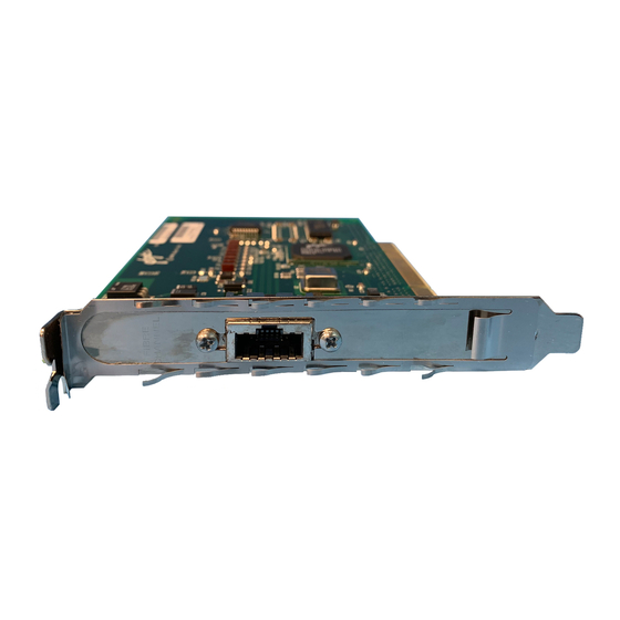
What You Need for Installation 2 – Hardware Installation SERIAL NUMBER Figure 2-1. QLA2000 Board Layout SERIAL NUMBER Figure 2-2. QLA2000F Board Layout FC0151102-00 D... -
Page 11: Qla2100 Board Layout
2 – Hardware Installation What You Need for Installation SERIAL NUMBER Figure 2-3. QLA2100 Board Layout SERIAL NUMBER Figure 2-4. QLA2100F Board Layout FC0151102-00 D... -
Page 12: Power Supply
2 – Hardware Installation Figure 2-5. QLA2102F Board Layout Power Supply The QLA2000/2100 boards supply +5 volts to pin 7 of the HSSDC copper interface to support an external media interface adapter (MIA). Installation in the Computer Perform the following steps to install the QLA2xxx board in your PC: 1. - Page 13 The BIOS lists all FC devices attached to the QLA2xxx board. For example: QLogic Corporation QLA2xxx PCI Fibre Channel ROM BIOS Version X.XX Copyright (C) QLogic Corporation 1998 All rights reserved. www.qlc.com Press <Alt-Q> for Fast!UTIL ISP2xxx Firmware Version X.XX...
-
Page 14: Installation Help
You have successfully installed the QLA2xxx board in your computer. See the appropriate QLogic software installation guide for detailed instructions on how to install the software drivers. If the information displayed is not correct and you have checked the QLA2xxx board’s configuration, see section 3 for troubleshooting information. -
Page 15: Section 3 Troubleshooting
Section 3 Troubleshooting Problems After Installation There are three basic types of installation problems that can cause your QLA2xxx board to function incorrectly: hardware problems, system configuration problems, and Fibre Channel problems. The following section provides itemized checklists to help you determine why your QLA2xxx board is not functioning. Hardware Problem Checklist Are all of the circuit cards installed securely in the PC? Are all of the cables securely connected to the correct connectors? Be sure... -
Page 16: System Configuration Problem Checklist
System Configuration Problem Checklist 3 – Troubleshooting System Configuration Problem Checklist Check the motherboard for proper configuration (see section 2.4). See the documentation supplied with your computer, or contact your computer dealer to determine if your motherboard requires configuration. If the system message Missing Operating System or No ROM BASIC, System Halted appears, the disk drive attached to the QLA2xxx board is not partitioned in a format compatible with the board. -
Page 17: Appendix A Fast!Util
Appendix A Fast!UTIL Introduction This appendix provides detailed configuration information for advanced users who want to customize the configuration of the QLA2xxx board and the connected devices. The board can be configured using Fast!UTIL. Access Fast!UTIL by pressing <ALT>-<Q> during the QLA2xxx board BIOS initialization (it may take a few seconds for the Fast!UTIL menu to appear). -
Page 18: Selectable Boot Settings
Configuration Settings A – Fast!UTIL Table A-1. Host Adapter Settings (Continued) Setting Options Default Adapter Hard Loop ID Enabled or Disabled Disabled Hard Loop ID 0-125 Host Adapter BIOS. When this setting is disabled, the ROM BIOS on the QLA2xxx board is disabled, freeing space in upper memory. Do not disable this setting if you are booting from an FC disk drive attached to the QLA2xxx board. -
Page 19: Raw Nvram Data
A – Fast!UTIL Configuration Settings A.2.4 Raw NVRAM Data This option displays the adapter’s NVRAM contents in hexadecimal format. This is a troubleshooting tool; you cannot modify the data. A.2.5 Advanced Adapter Settings From the Configuration Settings menu in Fast!UTIL, select Advanced Adapter Settings. - Page 20 Configuration Settings A – Fast!UTIL LUNs per Target. This setting specifies the number of LUNs per target. Multiple LUN support is typically for redundant array of independent disks (RAID) boxes that use LUNs to map drives. The default is 8. If you do not need multiple LUN support, set the number of LUNs to 0.
-
Page 21: Scan Fibre Channel Devices
A – Fast!UTIL Scan Fibre Channel Devices Scan Fibre Channel Devices This option scans the FC loop and lists all the connected devices by loop ID. Information about each device is listed, for example, vendor name, product name, and revision. This information is useful when configuring your QLA2xxx board and attached devices. - Page 22 Select Host Adapter A – Fast!UTIL FC0151102-00 D...
-
Page 23: Appendix B Specifications
3.3 V and 5.0 V busses supported environment PCI transfer rate 132 Mbytes/sec maximum burst rate (ISP2100 chip, QLA2000/2000F) 264 Mbytes/sec maximum burst rate for 33 MHz operation (ISP2100 chip, QLA2100/2100F/2102F) 528 Mbytes/sec maximum burst rate for 66 MHz operation... - Page 24 Three independent DMA channels: two data and one command. Integrated 4K-byte frame buffer FIFO for each data channel Connectors QLA2000/2100: HSSDC connector that supports copper cabling. (external) Fibre optic support available using an external MIA. QLA2000F/2100F/2102F: SC-style connector that supports non-OFC, multimode fibre optic cabling using 1x9 fibre optic...
Need help?
Do you have a question about the QLA2000 and is the answer not in the manual?
Questions and answers