
Related Manuals for Kenwood CK 230


Summary of Contents for Kenwood CK 230
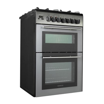
- Page 1 GAS COOKER with ELECTRIC DOUBLE OVEN CK 230 Instructions for use - Installation advice...
-
Page 3: Table Of Contents
CONTENTS Page Number Introduction ..........4 - 5 Important Safeguards &... -
Page 4: Introduction
Dear Customer, Thank you for purchasing a Kenwood Dual Fuel Double Oven Cooker. The safety precautions and recommendations in these instructions are for your own safety and that of others. They will also provide a means by which to make full use of the features offered by your appliance. - Page 5 FIRST USE OF THE OVEN Follow the instructions below: – Furnish the interior of the oven by placing the wire racks as described in “Cleaning and maintenance”. – Insert shelves and tray. – Switch the empty oven on to max to eliminate grease from the heating elements. See pages 12, 14.
-
Page 6: Important Safeguards & Recommendations
IMPORTANT SAFEGUARDS WARNING AND RECOMMENDATIONS When correctly installed, your prod- uct meets all safety requirements laid down for this type of product catego- After unpacking the appliance, check to ry. However special care should be ensure that it is not damaged and that taken around the rear or the under- the oven door closes correctly. -
Page 7: Cooking Hob
1 - COOKING HOB Fig. 1.1 Fig. 1.1 COOKING HOB 1. Auxiliary burner (A) - 1,00 kW 2. Semi-rapid burner (SR) - 1,75 kW 3. Triple ring burner (TC) - 3,50 kW... -
Page 8: Control Panel
2 - CONTROL PANEL Fig. 2.1 CONTROL PANEL - Controls description 1. Front right burner control knob 2. Rear right burner control knob 3. Rear left burner control knob 4. Front left burner control knob 5. Conventional oven temperature knob (Top oven) 6. -
Page 9: Use Of Cooking Hob
3 - USE OF COOKING HOB GAS BURNERS The maximum setting permits rapid boiling of liquids, whereas the minimum Each burner is controlled by a gas tap setting allows slower warming of food which opens and closes the gas supply. or maintaining simmering conditions of Line the control knob symbol up with the liquids. - Page 10 DEEP FAT FRYING CHOICE OF THE BURNER For safety purposes when deep fat fry- On the control panel, near each knob, ing, do not fill the pan more than one there is a diagram that indicates which third full of oil. burner is controlled by that knob.
-
Page 11: Correct Use Of Triple-Ring Burner
CORRECT USE OF TRIPLE-RING BURNER (Fig. 3.4a - 3.4b) Flat-bottomed pans should be placed directly onto the pan-support. When using a WOK always place the supplied stand in position over the burner to main- tain the correct operation of the triple-ring burner (Fig. 3.4a - 3.4b). IMPORTANT: The special grille for wok pans (fig. -
Page 12: Top Conventional Electric Oven
4 - TOP CONVENTIONAL ELECTRIC OVEN NOTE: When using for the first time, Attention: the oven door becomes you are advised to run the oven at maxi- very hot during operation. mum temperature (temperature knob Keep children away. set to 250°C) for approximately one hour in the mode and for another 15 minutes in the... - Page 13 TEMPERATURE KNOB (fig. 4.2) GRILLING This only sets the cooking temperature but does not switch the oven on. The infra-red heating element is switched Rotate clockwise until the required tem- on. The heat is diffused by radiation. perature is reached (from 50 to 250 °C). Use with the oven door closed and the The light above the knob will illuminate temperature knob to 175°C.
-
Page 14: Bottom Main Oven
5 - BOTTOM MAIN OVEN Attention: the oven door becomes very hot during operation. Keep children away. SWITCH AND TEMPERATURE SELECTOR Turn the selector knob (fig. 5.1) to the required function. OFF - as per fig. 5.1 The oven light is switched on. The fan operates without the heating element, this function can be used for defrosting. -
Page 15: Cooking Guide
6 - COOKING GUIDE Temperature and times given are approximate, as they will vary depending on the quality and amount of food being cooked. Remember to use ovenproof dishes and to adjust the oven temperature during cooking if necessary. COOKING CHART Temperature Food Cooking Time (approx) -
Page 16: Electronic Clock/End Cooking Timer (Main Oven Only)
7 - ELECTRONIC CLOCK/END COOKING TIMER (Main oven only) COOKING WITH AUTOMATIC The electronic programmer performs the following functions: SWITCH-OFF (Main oven only) – 24 hours clock with illuminated This function automatically stops the display cooking after a pre programmed time, –... -
Page 17: Cleaning & Maintenance
8 - CLEANING AND MAINTENANCE Important: WARNING Before cleaning or carrying out any When correctly installed, your prod- maintenance disconnect the appli- uct meets all safety requirements laid ance from the electrical supply and down for this type of product cate- wait for it to cool down. - Page 18 REPLACING THE OVEN LIGHT BULB BURNERS Switch the cooker off at the mains. They can be removed and washed with When the oven is cool, unscrew and soapy water only. replace the bulb with another one They will remain always perfect if resistant to high temperatures (300°C), cleaned with products used for silver- voltage 230 V (50 Hz), 15 W, E14.
- Page 19 CORRECT REPLACEMENT OF THE TRIPLE RING BURNER BURNERS The triple ring burner must be correctly positioned (see fig. 8.3); the burner rib It is very important to check that the must be enter in their logement as burner flame distributor F and the cap C shown by the arrow.
- Page 20 USING THE TOP AND THE MAIN OVEN FOR THE FIRST TIME You are advised to carry out the follow- ing operations: – Clean the inside of the two ovens with a cloth soaked in water and neutral detergent and dry thoroughly. –...
- Page 21 Type A REMOVING THE OVEN DOOR To facilitate oven cleaning, it is possible to remove the door. Please follow the instructions carefully: – Open the door completely. – Push down the lever “L” and, keeping it in this position, slowly close the door in order to block the hinge.
- Page 22 Type B Fig. 8.13A REMOVING THE OVEN DOOR The oven door can easily be removed as follows: – Open the door to the full extent (fig. 8.13A). – Attach the retaining rings to the hooks on the left and right hinges (fig. 8.13B).
-
Page 23: Advice For The Installer
Advice for the installer IMPORTANT – The appliance is designed and approved for domestic use only and should not be installed in a commercial, semi commercial or communal environment. Your product will not be guaranteed if installed in any of the above environments and could affect any third party or public liability insurances you may have. -
Page 24: Installation
9 - INSTALLATION INSTALLATION This cooker has class “2/1” overheating protection so that it can be installed next to a cabinet. The furniture walls adjacent to the cooker must be made of heat-resistant material. The veneered synthetic material and the glue used must be resistant to a temperature of 90°C in order to avoid ungluing or deformations. - Page 25 If the cooker is installed adjacent to furniture which is higher than the gas hob cooktop, a gap of at least 50 mm must be left between the side of the cooker and the furniture. The appliance may be installed in a kitchen, Kitchen/diner or a bed sitting room, but not in a room or space containing a bath or a shower.
-
Page 26: Gas Section
10 - GAS SECTION GAS INSTALLATION GAS CONNECTION IMPORTANT NOTE The installation of the cooker to Natural This appliance is supplied for use on Gas or LP Gas must be carried out by a NATURAL GAS only and cannot be used qualified gas engineer. - Page 27 GAS CONNECTION Left gas Right gas inlet pipe The gas supply must use the nearest inlet pipe gas inlet pipe which is located at the left or the right hand side at the rear of the appliance (fig. 10.1). The unused end inlet pipe must be closed with the plug interposing the gasket.
- Page 28 CONVERSION TO LPG OPERATIONS TO BE EXECUTED FOR THE REPLACEMENT OF THE INJECTORS OF THE TOP BURNERS If the injectors are not supplied they can be obtained from the “Service Centre”. The diameter is marked on the injector in cents of millimetre. Select the injectors to be replaced according to the “Table for the choice of the injec- tors”...
- Page 29 ADJUSTMENT OF THE MINIMUN OF THE TOP BURNERS In the minimum position the flame must have a length of about 4 mm and must remain lit even with a quick turn from the maximum position to that of minimum. The flame adjustment is done in the following way: –...
- Page 30 TABLE FOR THE CHOICE OF THE INJECTORS Cat: 2H3+ G 30 - 28-30 mbar G 20 Reduced Nominal BURNERS G 31 - 37 mbar 20 mbar Power Power By-pass By-pass Ø injector Ø injector [kW] [kW] [1/100 mm] [1/100 mm] [1/100 mm] [1/100 mm] 1,00...
-
Page 31: Electrical Section
11 - ELECTRICAL SECTION N.B. For connection to the mains, do not use adapters, reducers or IMPORTANT: The cooker must branching devices as they can cause be installed in accordance with overheating and burning. the manufacturer’s instructions. Incorrect installation, for which If the installation requires alterations to the manufacturer accepts no the domestic electrical system, call an... -
Page 32: Technical Data
Connecting the mains cable Technical data – Remove the two screws securing 230 V AC - 50 Hz the cover plate A behind the cooker. – Remove the screw C from the cable Top conventional oven clamp. – Top element 0.70 kW –... -
Page 33: Guarantee
GUARANTEE UK only If your appliance goes wrong within one year from the date you bought it, we will repair it (or replace it if necessary) free of charge provided: • you have not misused, neglected, or damaged it; • it has not been modified; •... -
Page 34: After Sales Service
AFTER SALES SERVICE If you require After Sales Service contact the MASTERCARE Domestic Appliance Helpline Telephone 08701 565550. Ser. Nr. Descriptions and illustrations in this booklet are given as simply indicative. The manufacturer reserves the right, considering the characteristics of the models described here, at any time and without notice, to make eventual necessary modifications for their construction or for commercial needs. - Page 36 code 1102953 - ß5...
Need help?
Do you have a question about the CK 230 and is the answer not in the manual?
Questions and answers