Table of Contents
Advertisement
INSTALLATION INSTRUCTION
208/230/575
VOLT ONLY
GENERAL
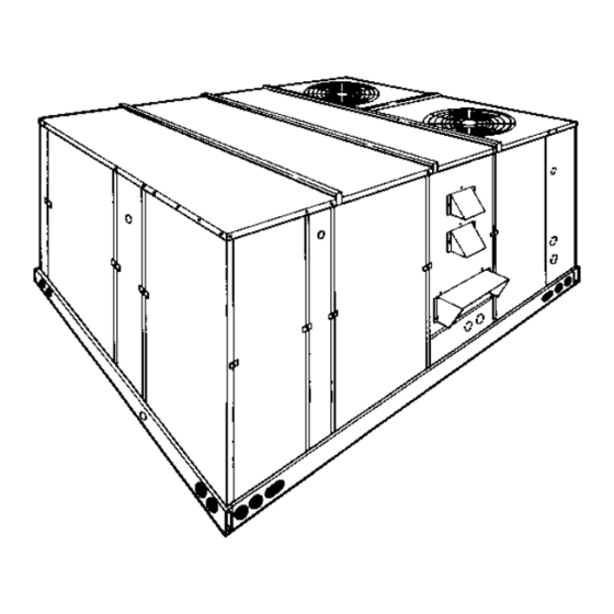
YORK Model DCE and DCG units are single package air
conditioners designed for outdoor installation on a rooftop or a
slab and is manufactured under ISO 9002 Quality System
Certification. The DCE models are cooling only and can be
equipped with factory installed electric heaters for cooling /
heating applications. The DCG models are gas-fired central
heating furnaces with cooling.
The units are completely assembled on rigid, permanently
attached base rails. All piping, refrigerant charge, and electrical
wiring is factory installed and tested. All units require electric
power, duct connections and fixed outdoor air intake damper
(units without economizer or motorized damper option only) at
the point of installation.
The DCG units additionally require gas connection, installation
of the combustion air inlet hood and the flue gas outlet hoods
at the point of installation. The gas-fired heaters have
aluminized-steel tubular heat exchangers and spark ignition
with proven pilot.
S u pp l em e nt a l e l ec t ri c h ea te rs fo r D C E u ni ts ha ve
nickel-chrome elements and utilize single point power
connections.
The following safety precautions apply to DCG units:
FOR YOUR SAFETY
If you smell gas:
1. Open windows.
2. Don't touch electrical switches
3. Extinguish any open flame.
4. Immediately call your gas supplier.
Do not store or use gasoline or other flammable
vapors and liquids in the vicinity of this or any
other appliance
INSPECTION
As soon as a unit is received, it should be inspected for possible
damage during transit. If damage is evident, the extent of the
Installer should pay particular attention to the words: NOTE, CAUTION and WARNING . Notes are intended to clarify or make
the installation easier. Cautions are given to prevent equipment damage. Warnings are given to alert installer that personal injury
and/or equipment damage may result if installation procedure is not handled properly.
®
Supersedes: 530.18-N11Y (793)
MODELS D1CE & D1CG300
FOR YOUR SAFETY
.
SUNLINE 2000™
ELECTRIC / ELECTRIC & GAS / ELECTRIC
SINGLE PACKAGE AIR CONDITIONERS
(Constant Air Volume)
(8.5 EER)
DCG MODEL
SHOWN
damage should be noted on the carrier's freight bill. A separate
request for inspection by the carrier's agent should be made in
writing. Refer to Form 50.15-NM for additional information.
REFERENCE
Additional information on the design, installation, operation and
service of this equipment is available in the following reference
forms:
•
55.70-N1
- General Installation
•
55.70-N2
- Pre-start & Post-start Check List
•
44-320-10
- Barometric Relief Damper Accessory
•
530.18-N6.1V - Propane Conversion Accessory
•
530.18-N6.2V - High Altitude Accessory (Nat. Gas)
•
530.18-N6.3V - High Altitude Accessory (Propane)
Renewal Parts:
•
Refer to the Renewal Parts Manual for complete listing of
replacement parts on this equipment.
All forms referenced in this instruction may be ordered from:
Publications Distribution Center
Unitary Products Group
P.O. Box 1592, York, Pa. 17405
APPROVALS
Design certified by ETL & CGA as follows:
1. For use as a central cooling only unit with or without
supplemental electric heat. (DCE models)
2. For use as a forced air furnace with cooling unit. (DCG
models)
3. For use with natural gas or propane gas. (DCG models)
4. For outdoor installation only.
5. For installation on combustible material.
THIS PRODUCT MUST BE INSTALLED IN STRICT COMPLIANCE
WITH THE ENCLOSED INSTALLATION INSTRUCTIONS AND ANY
A PPLICAB LE LOCA L, STATE, AND NATIONAL CODES
INCLUDING, BUT NOT LIMITED TO, BUILDING, ELECTRICAL,
AND MECHANICAL CODES.
INCORRECT INSTALLATION MAY CREATE A CONDITION
WHERE THE OPERATION OF THE PRODUCT COULD CAUSE
PERSONAL INJURY OR PROPERTY DAMAGE
530.18-N11Y (195)
035-12550
208/230/460
VOLT ONLY
CAUTION
WARNING
Advertisement
Table of Contents

Related Manuals for York D1CE


Summary of Contents for York D1CE
-
Page 1: Installation Instruction
GENERAL request for inspection by the carrier’s agent should be made in YORK Model DCE and DCG units are single package air writing. Refer to Form 50.15-NM for additional information. conditioners designed for outdoor installation on a rooftop or a... -
Page 2: Table Of Contents
530.18-N11Y TABLE OF CONTENTS General ................1 MAINTENANCE & TROUBLESHOOTING Inspection................1 Normal Maintenance............20 Reference ................1 Cleaning Flue Passages and Heating Elements ....20 Approvals ................1 Troubleshooting ..............21 Nomenclature............... 2 TABLES INSTALLATION Description Page Limitations ................3 Unit Application Data ........ -
Page 3: Installation
CAUTION: If a unit is to be installed on a roof curb or LIMITATIONS special frame other than a YORK roof curb, These units must be installed in accordance with the following gasketing must be applied to all surfaces that applicable national and local safety codes: come in contact with the unit underside. -
Page 4: Ductwork
530.18-N11Y DUCTWORK Ductwork should be designed and sized according to the methods in Manual Q of the Air Conditioning Contractors of America (ACCA). A closed return duct system shall be used. This shall not preclude use of economizers or outdoor fresh air intake. The supply and return air duct connections at the unit should be made with flexible joints to minimize noise. -
Page 5: Typical Field Wiring
530.18-N11Y CONTROL WIRE SIZES Wire Size AWG. Gauge Maximum Wire Length Feet Notes: 1. Solid, Class II copper wire FIG. 5 - TYPICAL FIELD WIRING Unitary Products Group... -
Page 6: Thermostat
530.18-N11Y THERMOSTAT COMBUSTION DISCHARGE (DCG Models) The room thermostat should be located on an inside wall The products of combustion are discharged horizontally approximately 56" above the floor where it will not be subject through two screened (hooded) openings on the upper gas to drafts, sun exposure or heat from electrical fixtures or heat access panel. -
Page 7: Units, Tanks And Piping (Dcg Models)
530.18-N11Y L.P. UNITS, TANKS AND PIPING (DCG Models) All gas heat units are shipped from the factory equipped for natural gas use only. The unit may be converted in the field for use with L.P./propane gas with accessory kit model number 1NP0418. -
Page 8: Vent And Combustion Air Hoods (Dcg Models)
530.18-N11Y VENT AND COMBUSTION AIR HOODS OPTIONAL ECONOMIZER/MOTORIZED DAMPER RAIN HOOD (DCG Models) The instruction for the optional economizer/motorized damper Two vent hoods and a combustion air hood (with screens) are rain hood can be found in form 44-320-2. Use these instructions shipped attached to the blower housing in the blower when field assembling an economizer rain hood onto a unit. - Page 9 530.18-N11Y FIG. 9 - ENTHALPY SETPOINT ADJUSTMENT Unitary Products Group...
-
Page 10: Physical Data
575-3-60 Utilization Range “A” in accordance with ARI Standard 110. TABLE 6- ELECTRICAL DATA - UNITS WITH ELECTRIC HEAT HEATER OPTION MINIMUM MAXIMUM MODEL POWER CIRCUIT OVERCURRENT MINIMUM D1CE SUPPLY AMPACITY DEVICE WIRE SIZE MODEL STAGES AMPS (AMPS) (AMPS) E018 13.5... -
Page 11: Utilities Entry Data
530.18-N11Y All dimensions are in inches. They are sub- ject to change without notice. Certified di- mensions will be provided upon request. 52-5/8 RETURN AIR SUPPLY AIR 136-1/4 CONDENSER AIR OUTDOOR AIR (Economizer) UNITS 35-1 UTILITIES ENTRY DATA OPENING HOLE SIZE USED FOR (DIA.) - Page 12 530.18-N11Y DUCT COVERS - Units are shipped with the bottom duct openings covered. An accessory flange kit is avail- able for connecting side ducts. For bottom duct applications: 1. Remove the side panels from the supply and return air compartments to gain access to the bottom supply and return air duct covers.
-
Page 13: Supply Air Blower Performance
530.18-N11Y TABLE 7 - SUPPLY AIR BLOWER PERFORMANCE DCE300 - BOTTOM DUCT CONNECTIONS COOLING APPLICATIONS) MOTOR BLOWER PULLEY 8,000 9,000 10,000 11,000 12,000 SPEED, (TURNS (RPM) OPEN)* STANDARD DRIVE 1010 6.0** 10.4 1064 11.1 12.7 10.6 1118 10.3 11.9 10.0 13.6 11.4 15.4... -
Page 14: Static Resistances
530.18-N11Y TABLE 8 - STATIC RESISTANCES* EXTERNAL STATIC PRESSURE DROP RESISTANCE, IWG DESCRIPTION 9,000 10,000 11,000 WET COIL GAS HEAT 18 KW 36 KW ELECTRIC HEAT OPTIONS 54 KW 72 KW ECONOMIZER OPTION INLET GUIDE VANCES HORIZONTAL DUCT CONNECTIONS Deduct these resistance values from the available unit ESP values listed in the respective blower performance table except for Horizontal Duct Connections (Shaded ). -
Page 15: Operation
530.18-N11Y OPERATION single sensor except that a second enthalpy sensor is mounted COOLING SYSTEM in the return air. This return air sensor allows the economizer The cooling section is a complete factory package utilizing an to choose between outdoor air and return air, whichever has air-cooled condenser. -
Page 16: Gas Heating Sequence Of Operation
530.18-N11Y on the 72 KW, 240V heater, heater contactors (8M & 9M) inside the second stage main gas valve ”GV2" to allow a flow will be energized. of gas to the second stage carryover tube. See Figure 13. Only after the pilot flame has been ignited and the presence of pilot c) The thermostat will cycle the electric heat to satisfy the flame detected at “IC2"... -
Page 17: Pre-Start Check List
530.18-N11Y HEAT ANTICIPATOR SETPOINTS It is important that the anticipator setpoint be correct. Too high of a setting will result in longer heat cycles and a greater temperature swing in the conditioned space. Reducing the value below the correct setpoint will give shorter “ON” cycles and may result in the lowering of the temperture within the conditioned space. -
Page 18: Pilot Checkout
530.18-N11Y PILOT CHECKOUT CHECKING SUPPLY AIR CFM The RPM of the supply air blower will depend on the required CFM, The pilot flame should envelope the end of the flame sensor. the unit accessories or options and the static resistances of both Refer to Figure 14. -
Page 19: Adjustment Of Temperature Rise
530.18-N11Y 3. Using an inclined manometer, determine the pressure drop After about 20 minutes of operation, determine the furnace across a dry evaporator coil. Since the moisture on an temperature rise. Take readings of both the return air and the evaporator coil may vary greatly, measuring the pressure heated air in the ducts (about six feet from the furnace) where drop across a wet coil under field conditions would be... -
Page 20: Normal Maintenance
530.18-N11Y MAINTENANCE TO CLEAN BURNERS - Remove them from the furnace as NORMAL MAINTENANCE explained in “Burner Instructions”. Clean burners with hot water CAUTION: Prior to any of the following maintenance proce- applied along top of the burner. dures, shut off all electric power to the unit to COMBUSTION AIR DISCHARGE - Visually inspect discharge prevent personal injury. -
Page 21: Troubleshooting
530.18-N11Y TROUBLESHOOTING WARNING: Troubleshooting of components necessarily re- c. If (3M) is pulled in and the blower motor still does not quires opening the electrical control box with the run, replace the blower motor. power connected to the unit. Use extreme care when working with live circuits! Check the unit d. - Page 22 530.18-N11Y TROUBLESHOOTING - Cont’d. If lock-out continues to occur, locate the source of the d. If 24 volts is present, remove the pilot burner and problem and correct. remove the pilot orifice from the pilot burner. The orifice is removed in the direction opposite the flow of gas. b.
- Page 23 530.18-N11Y Unitary Products Group...
- Page 24 Unitary Products Group P.O. Box 1592, York, Pennsylvania USA 17405-1592 Subject to change without notice. Pri n ted in U.S.A. 530.18-N11Y Copyright © by York International Corporation 1995. All Rights Reserved. Code: SBY...
Need help?
Do you have a question about the D1CE and is the answer not in the manual?
Questions and answers