Advertisement
INSTALLATION INSTRUCTION
GENERAL
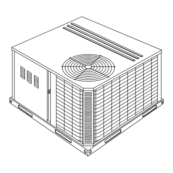
Model D1EB units are factory assembled cooling only air condi-
tioners designed for outdoor installation on a rooftop or a slab.
Field-installed electric heater accessories are available to provide
electric heat combined with electric cooling. All units and heaters
are certified by AGA and CGA.
The units are completely assembled on rigid, but easily remov-
able base rails. All piping, refrigerant charge, and electrical wir-
ing is factory installed and tested. The units require only electric
power and duct connections at the point of installation.
The electric heaters have nickel-chrome resistance wire ele-
ments and utilize single point power connection.
INSPECTION
As soon as a unit is received, it should be inspected for possible
damage during transit. If damage is evident, the extent of the
damage should be noted on the carrier's freight bill. A separate
request for inspection by the carrier's agent should be made in
writing. Refer to Form 50.15-NM for additional information.
Installer should pay particular attention to the words: NOTE, CAUTION and WARNING. Notes are intended to clarify or make
the installation easier. Cautions are given to prevent equipment damage. Warnings are given to alert installer that personal injury
and/or equipment damage may result if installation procedure is not handled properly.
®
SINGLE PACKAGE AIR CONDITIONERS
ELECTRIC/ELECTRIC, AIR-COOLED
Supersedes: 035-16703-000-A-0701
MODELS D1EB018 THRU 060
1-1/2 THRU 5 TON
(10 SEER)
CAUTION
THIS PRODUCT M UST BE INSTALLED IN STRICT COMPLIANCE W ITH
THE ENCLOSED INSTALLATION INSTRUCTIONS AND ANY APPLICABLE
LOCAL, STATE, AND NATIONAL CODES INCLUDING, BUT NOT LIMITED
TO, BUILDING, ELECTRICAL, AND MECHANICAL CODES.
WARNING
INCORRECT INSTALLATION MAY CREATE A CONDITION WHERE THE
OPERATION OF THE PRODUCT COULD CAUSE PERSONAL INJURY
O R P R O P E R T Y D A M A G E .
Get other manuals https://www.bkmanuals.com
CHAMPION
SERIES
®
REFERENCE
Additional information on the design, installation, operation
and service of this equipment is available in the following refer-
ence forms:
• 55.70-N1
-General Installation
• 55.70-N2
-Pre-start & Post-start Check List
• 511.26-N1.1V -Electric Heater Accessory
REPLACEMENT PARTS
• Refer to Replacement Parts Manual for complete listing of
replacement parts on this equipment.
All forms referenced in this instruction may be ordered from:
Standard Register
Norman, OK 73069
Toll Free: Tel. 877-318-9675/Fax. 877-379-7920
035-16703-001-A-0202
Advertisement
Table of Contents

Related Manuals for York CHAMPION D1EB018


Summary of Contents for York CHAMPION D1EB018
- Page 1 ® CHAMPION SERIES ® SINGLE PACKAGE AIR CONDITIONERS ELECTRIC/ELECTRIC, AIR-COOLED INSTALLATION INSTRUCTION Supersedes: 035-16703-000-A-0701 035-16703-001-A-0202 MODELS D1EB018 THRU 060 1-1/2 THRU 5 TON (10 SEER) GENERAL REFERENCE Model D1EB units are factory assembled cooling only air condi- Additional information on the design, installation, operation tioners designed for outdoor installation on a rooftop or a slab.
-
Page 2: Installation
035-16703-001-A-0202 PRODUCT NOMENCLATURE PRODUCT CATEGORY VOLTAGE CODE D = Single Package Air Conditioner 06 = 208/230-1-60 NOMINAL COOLING (Air Cooled) 25 = 208/230-3-60 CAPACITY (MBH) 46 = 460-3-60 018 = 18,000 BTUH PRODUCT GENERATION 58 = 575-3-60 024 = 24,000 BTUH 1 = NEW or Current Design 030 = 30,000 BTUH FACTORY... - Page 3 035-16703-001-A-0202 CLEARANCES FILTERS All units require certain clearances for proper operation and Single phase units are shipped without a filter and is the responsi- service. Refer to Figure 3 for the clearances required for com- bility of the installer to secure a filter in the return air ductwork or bustion, construction, servicing and proper unit operation.
-
Page 4: Power And Control Wiring
035-16703-001-A-0202 POWER AND CONTROL WIRING Field wiring to the unit must conform to provisions of the current Electrical line must be sized properly to carry the load. Each N.E.C. ANSI/NFPA No. 70 or C.E.C. and/or local ordinances. unit must be wired with a separate branch circuit fed directly The unit must be electrically grounded in accordance with local from the meter panel and properly fused. - Page 5 035-16703-001-A-0202 TABLE 4 - ELECTRICAL DATA (BASIC UNIT) VOLTAGE SUPPLY MAX. MAX. COND. LIMITATIONS COMPRESSOR MINIMUM FUSE HACR UNIT MODEL POWER SUP- TRANSFORMER BLOWER CIRCUIT SIZE, BREAKER POWER MOTOR, SIZE (VA) MOTOR, AMPACITY SIZE, FACTOR AMPS MIN. MAX. AMPS 208/230-1-60 48.0 14.9 208/230-1-60...
-
Page 6: Electric Heat Accessory
035-16703-001-A-0202 TABLE 5 - ELECTRICAL DATA (COOLING / ELECTRIC HEAT) COMPRESSOR ELECTRIC HEAT ACCESSORY SUPPLY COND. MAX. MAX. MINIMUM POWER FUSE HACR BLOWER CIRCUIT SUPPLY MOTOR SIZE, BREAKER MOTOR, AMPACITY AMPS SIZE TOTAL MODEL NO. AMPS 2NH04500506 3.8/5.0 * 18.1/20.8 25.8/29.3 30/30 30/30... - Page 7 035-16703-001-A-0202 Checking Supply Air CFM a dry coil, the compressors should be deactivated while the test is being run. To check the supply air CFM after the initial balancing has been completed: 4.Knowing the pressure drop across a dry coil, the actual CFM through the unit can be determined from the curve in Coil Delta 1.Remove the two ¼...
-
Page 8: Outdoor Temperature
035-16703-001-A-0202 TABLE 6 - SUPERHEAT CHARGING TABLE FOR MODEL D1EB018 SUPERHEAT AT COMPRESSOR SUCTION (F), AIRFLOW = 600 CFM/TON OUTDOOR TEMPERATURE INDOOR WB TEMPERATURE (F) 17.8 19.8 21.8 23.9 25.9 27.9 29.9 31.1 32.3 33.6 34.8 12.2 14.9 17.5 20.2 22.8 25.4 28.1... - Page 9 035-16703-001-A-0202 TABLE 10 - SUPERHEAT CHARGING TABLE FOR MODEL D1EB042 SUPERHEAT AT COMPRESSOR SUCTION (F), AIRFLOW = 1,400 CFM/TON OUTDOOR TEMPERATURE INDOOR WB TEMPERATURE (F) 20.3 21.9 23.5 25.0 26.6 28.1 29.7 30.6 31.6 32.6 33.6 16.7 18.5 20.3 22.1 23.9 25.7 27.5...
- Page 10 035-16703-001-A-0202 HIGH VOLTAGE CONN. FRONT COMPRESSOR " DIA. KNOCKOUT & SERVICE ACCESS HIGH VOLTAGE CONN. COMPARTMENT PANEL " DIA. KNOCKOUT DIMENSION LOW VOLTAGE CONN. “A” UNIT SIZE “A” “ DIA. KNOCKOUT & (OVERALL) & 018 - 042 048 - 060 SIDE SUPPLY AIR OPENING REFRIGERANT...
-
Page 11: Sequence Of Operation
035-16703-001-A-0202 SEQUENCE OF OPERATION Cooling Heating The following sequences of operation are based on using a WITH POWER TO UNIT AND THERMOSTAT IN HEATING standard single-stage cooling thermostat. MODE. WITH POWER TO UNIT AND THERMOSTAT IN COOLING 1. If the fan switch on the thermostat is in the “ON” position, the 24 volts at “G”... -
Page 12: Secure Owner's Approval
035-16703-001-A-0202 TABLE 14 - THERMOSTAT SIGNALS (THREE PHASE UNITS) BOARD FUNCTION BOARD FUNCTION FAN INSTANT ON “G” OFF FAN INSTANT OFF FAN INSTANT ON FAN INSTANT ON COMPRESSOR AND OUTDOOR FAN INSTANT ON HEATER BANK 1, 2 AND 3 ELEC. HEAT INSTANT ON “G”... - Page 13 035-16703-001-A-0202 FOR DUAL POINT FOR DUAL POINT ELECTRIC HEAT ELECTRIC HEAT POWER SUPPLY POWER SUPPLY SEE DETAIL A SEE DETAIL A DETAIL "B" FOR DEFROST CONTROL 031-09104-000A SEE DETAIL C DEFROST CONTROL 031-01268-000B OPTIONAL CCH DETAIL C SECONDARY POWER SUPPLY SECONDARY POWER SUPPLY FOR DUAL POINT ELEC HEAT FOR DUAL POINT ELEC HEAT...
- Page 14 035-16703-001-A-0202 DETAIL A COMPR 222/Y RELAY DFST STAT FOR DEFROST CONTROL 031-09104-000A DEFROST SEE DETAIL A CONTROL 031-01268-000B FIG. 5 - TYPICAL WIRING DIAGRAM (230-3-60 POWER SUPPLY) Unitary Products Group Get other manuals https://www.bkmanuals.com...
- Page 15 035-16703-001-A-0202 E L E M E N T A R Y D I A G R A M P O W E R S U P P L Y W / O U T E L E C H E A T 4 6 0 - 3 - 6 0 O R 5 7 5 - 3 - 6 0 G N D U S E C O P P E R...
-
Page 16: Typical Wiring Diagram Legend
035-16703-001-A-0202 TYPICAL WIRING DIAGRAM LEGEND CIRCUIT BREAKER 24V, 3 AMP , 20, & 25 , 20, & 25 F7 F8 F9 20 & 25 ALL KW ELEC HEAT) , 20, & 25 20 & 25 KW ELEC HEAT) HTR 4 ELECTRIC HEATER (OPT. - Page 17 Unitary Products Group 5005 York Drive, Norman Oklahoma 73069 Subject to change without notice. Printed in U.S.A. 035-16703-001-A-0202 Copyright by York International Corporation 2001. All Rights Reserved. Supersedes 035-16703-000-A-0701 Get other manuals https://www.bkmanuals.com...
Need help?
Do you have a question about the CHAMPION D1EB018 and is the answer not in the manual?
Questions and answers