
Related Manuals for Celestron Advanced VX 91519


Summary of Contents for Celestron Advanced VX 91519
- Page 1 Series Telescopes INSTRUCTION MANUAL For Models: 91519 32054 32062 22020 12079 12026 12046 12067 12031...
-
Page 3: Table Of Contents
TABLE OF CONTENTS Introduction ........... 5 Advanced VX Mount . -
Page 5: Introduction
Introduction Congratulations on your purchase of the Celestron Advanced Your telescope is designed to give you years of fun and rewarding observations. However, there are a few things to VX telescope mount. The Advanced VX German equatorial mount has been designed with the highest quality materials to consider before using your telescope that will ensure your ensure stability and durability. -
Page 6: Advanced Vx Mount
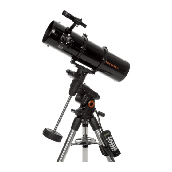
Advanced VX Mount (Advanced VX with 8” Edge HD Optical Tube Shown) Optical Tube Advanced VX Equatorial Mount Power Port DEC Motor Port Power Switch Tripod Auxiliary Ports Counterweight Hand Control Port Auto Guider Port Hand Control Control Panel R.A. Motor Housing Dec Motor Housing... -
Page 7: Assembly
flat, clear work area. A large floor space is ideal. When setting up your Celestron mount, you must start with 4. Place the equatorial mount on the tripod head so that the tripod and work up from there. - Page 8 Your Advanced VX tripod comes with the alignment peg installed so the polar axis and counterweight bar extends between two tripod legs. If you wish, you can reposition the alignment peg so the counterweight bar extends directly over a tripod leg. This is a matter of personal preference and does not affect the stability of the mount.
- Page 9 2. Remove the counterweight safety screw on the bottom that the mount does not move suddenly while attaching the end of the counterweight bar by turning it counterclock- telescope. To mount the telescope tube: wise. This screw prevents the counterweight from falling off the mount in the case the counterweight locking screw telescope mounting platform.
- Page 10 Balancing the Mount in R.A. telescope until the tube is parallel to the ground. To eliminate undue stress on the mount, the telescope should be properly balanced around the polar axis. Proper 4. Release the tube — GRADUALLY — to see which way it balancing is crucial for accurate tracking.
- Page 11 12V AC adapter. Use only Turn the azimuth adjustment knobs located on either side of adapters supplied by Celestron. Using any other adapter the azimuth housing. While standing behind the telescope, may damage the electronics and will void your manufacturer’s the knobs are on the front of the mount.
-
Page 12: Computerized Hand Control
Computerized Hand Control The Advanced VX uses the NexStar+ hand control that is designed to give you instant access to all the functions your mount has to offer. With automatic slewing to over 40,000 objects and common sense menu descriptions, even a beginner can The NexStar+ hand controller: 12 I... - Page 13 Quick-Align will ask you to input all the same information as you would for the Two Star Align procedure. However, 7. Option (Celestron Logo): Can be used in combination instead of slewing to the alignment stars for centering and with other keys to access more advanced features and alignment, the telescope bypasses this step and simply functions.
- Page 14 Note: If incorrect information is entered into the hand control, allowing the user to re-enter the correct data. information into the hand control. Select one of the alignment methods as described below. 3. The following information will be displayed: Location Two Star Align choose from.
- Page 15 Note: East/West Filtering 3. Use the UP and Down keys to select Sun Menu and possible full-sky pointing accuracy, your computerized press ENTER. mount automatically filters and chooses its initial 4. Press ENTER again to allow the Sun to appear on the alignment stars so that the first two alignment stars hand control display.
-
Page 16: Object Catalog
Slewing to an Object method, you can use Re-Align to align on actual objects in the sky. This will improve the pointing accuracy of your Once the desired object is displayed on the hand control telescope without having to re-enter additional information. screen, you have two options: Press the OBJECT INFO Key. - Page 17 ENTER. choose a speed rate. To use this feature, simply press the arrow button that corresponds to the direction that you want DOWN key. to move the telescope. While holding that button down, press the opposite directional button. This will increase the Identify Button speed to the maximum slew rate.
- Page 18 Option displays objects that are higher in altitude than 20°. button (the Celestron logo) for 10 seconds while Tip: If you want to explore the entire object database, set powering up the telescope.
- Page 19 GoTo Approach respond when it is slewing to objects that are accessible the telescope will approach when slewing to an object. This from both sides of the Meridian. The Meridian feature allows allows the user the ability to minimize the effects of backlash the telescope tube to remain on a desired side of the mount when slewing from object to object.
- Page 20 tracking in the same direction past the Meridian without the Calibrate Mount need to “flip” the telescope around to the opposite side of and pointing accuracy of the telescope, the mount has built-in the mount (see Meridian feature above). Using the first example calibration routines allowing it to compensate for mechanical above, the user could slew the telescope in R.A.
- Page 21 Hibernate Turn On/Off RTC powered down and still retain its alignment when turned internal real time clock. When aligning, the telescope still back on. This not only saves power, but is ideal for those receives time information from the RTC. If you want to use that have their telescope permanently mounted or leave their the hand control database to find the coordinates of a telescope in one location for long periods of time.
- Page 22 telescope, they are only valid for that exact location. To To use Precise GoTo: save land objects, once again center the desired object in to select Precise GoTo. and press ENTER. The display will ask you to enter a number between 1 and 200 to identify the object. Press ENTER again to save this object to the database.
-
Page 23: Advanced Vx Main Menu Tree
Advanced VX Main Menu Tree Menu Tracking Mode EQ North EQ South Rate Sidereal Solar Lunar View Time-Site Saved Site Hand Control Light Control Keypad Level Display Level Scrolling Menu Toggle Bold Font Set Contrast Set Language Scope Setup See Diagram - Next Page Utilities See Diagram - Next Page User Objects... - Page 24 Advanced VX Main Menu Tree Custom Site Utilities Calibrate Mount Scope Setup Setup Time-Site City Database Home Position GoTo Anti-Backlash RA Positive RA Negative Factory Setting Dec Positive Version Dec Negative Get Axis Position Filter Limits Goto Axis Position Direction Button RA Button Hibernate Dec Button...
-
Page 25: Optical Tube Assemblies
Optical Tube Assemblies Depending on the telescope kit you purchased, you may have received one of the following optical tubes. This section of the manual will walk you through the setup of the basic types. Kit # 22020 32054 32062 12031 Optical Design Refractor... -
Page 26: Setting Up The Newtonian Reflector
3. Tighten the adjustment screws until they make contact Your refracting telescope can use eyepieces with both a with the finderscope body. 1.25” and 2” barrel diameters. To use a 2” barrel eyepiece, the 1.25” eyepiece adapter must first be removed. To do this, simply loosen the two chrome thumbscrews located around of the telescope. -
Page 27: Setting Up The Edge Hd & Schmidt-Cassegrain Optical Tubes
it does not obstruct the inner diameter of the eyepiece Eyepiece holder. 2. Slide the chrome portion of the eyepiece into the eyepiece holder. Star 3. Tighten the set screw to hold the eyepiece in place. Diagonal Chrome Portion Eyepiece Eyepiece Holder If you wish to change the orientation of the star diagonal, loosen the set screw on the visual back until the star... - Page 28 4. Insert the screws through the bracket and into the rear cell. Finderscope Nylon Adjustment Screw WARNING: If you remove the mounting bracket, do not completely thread the screws back into the rear cell of the telescope. The screws may be long enough to obstruct the movement of, and possibly damage the primary mirror.
-
Page 29: Aligning The Finderscope
Aligning the Finderscope change your latitude by one degree. As you can see from this example, the distance from the northern horizon to the The finderscope is adjusted using two adjustment screws, celestial pole is always equal to your latitude. located on the top and on the right (when looking though the finder) of the finder bracket and a spring-loaded pivot screw (located on the left side of the bracket). - Page 30 1. Slew the telescope to a bright star on the opposite side Down buttons on the hand controller to select Polar Align of the Meridian from your two alignment stars. from the list. the hand controller to select Calib. Stars from the list, and press Enter.
- Page 31 1. Polar align the telescope. For more information on polar Li le Dipper Dipper aligning, see the Polar Alignment section earlier in the manual. 2. Remove all visual accessories. 3. Thread the Radial Guider onto your telescope. Cassiopeia 4. Thread the T-Ring onto the Radial Guider. N.C.P Polaris (North Star)
- Page 32 4. Plug the autoguider cable into the autoguider port on the mount’s electronics panel. 5. To begin recording the drive’s periodic error, press the MENU button and select PEC from the Utilities menu. option and press ENTER. When you are ready to record, press the ENTER button again to begin.
-
Page 33: Appendix A - Advanced Vx Mount Technical Specifications
Appendix A – Advanced VX Mount Technical Specifications Payload Capacity (excluding counterweight) 30 Pounds Optical Mounting System Standard Vixen-style “V” dovetail bar Computerized Hand Control 40,000+ objects, 100 user-defined programmable objects. Database Enhanced information on over 200 objects Slew Speeds Tracking Modes EQ North, EQ South, Off Tracking Rates... - Page 34 2835 Columbia Street Celestron, is found to be defective in materials or workmanship. As Torrance, CA 90503 a condition to the obligation of Celestron to repair or replace such product, the product must be returned to Celestron together with Tel. 800.421.9649 proof-of-purchase satisfactory to Celestron.
Need help?
Do you have a question about the Advanced VX 91519 and is the answer not in the manual?
Questions and answers