Table of Contents
Advertisement
Advertisement
Table of Contents

Related Manuals for Celestron Advanced Series C10-N


Summary of Contents for Celestron Advanced Series C10-N
- Page 1 ● ●...
-
Page 2: Table Of Contents
Installing the Counterweight ... 9 Attaching the Hand Control Holder ... 9 Attaching the Slow Motion Knobs ... 9 Attaching the Telescope Tube to the Mount... 10 Installing the Finderscope ... 11 Installing the Eyepieces... 11 Balancing the Tube in R.A... 12 Adjusting the Mount ... - Page 3 TELESCOPE BASICS ... 29 Image Orientation ... 29 Focusing... 30 Aligning the Finderscope ... 30 Calculating Magnification... 30 Determining Field of View ... 31 General Observing Hints... 31 ASTRONOMY BASICS... 32 The Celestial Coordinate System ... 32 Motion of the Stars... 33 Finding the North Celestial Pole ...
-
Page 4: Introduction
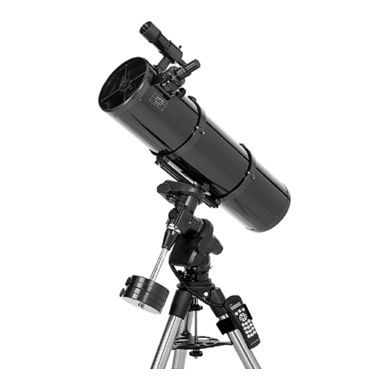
Congratulations on your purchase of the Celestron Advanced Series telescope (AST)! The Advanced Series of telescopes come in standard (non-computerized) and computerized GT models. The Advanced Series is made of the highest quality materials to ensure stability and durability. All this adds up to a telescope that gives you a lifetime of pleasure with a minimal amount of maintenance. - Page 5 Fig 1-1 - The Advanced Series Newtonian Finderscope Finderscope Bracket Eyepiece Focuser Tube Rings Latitude Adjustment Lever (C8-N Shown) 2" Steel Tripod Center Leg Brace / Accessory Tray Counterweights Counterweight Bar Dovetail Slide Bar Optical Tube...
-
Page 6: Control Panel
Fig 1-2 - The Advanced Series GT Newtonian Finderscope Finderscope Bracket Eyepiece Focuser Tube Rings Latitude Adjustment Lever 2" Steel Tripod CONTROL PANEL Hand Control Port DEC Motor Port Autoguide Port (C8-NGT Shown) Center Leg Brace / Accessory Tray Counterweights Counterweight Bar Dovetail Slide Bar Optical Tube... -
Page 7: Assembly
This section covers the assembly instructions for your Celestron Advanced Series Telescope (AST). Your AST telescope should be set up indoor the first time so that it is easy to identify the various parts and familiarize yourself with the correct assembly procedure before attempting it outdoor. -
Page 8: Attaching The Center Leg Brace
Once the bar is securely in place you are ready to attach the counterweight. Since the fully assembled telescope can be quite heavy, position the mount so that the polar axis is pointing towards north before the tube assembly and counterweights are attached. This will make the polar alignment procedure much easier. -
Page 9: Installing The Counterweight
Depending on which AST telescope you have, you will receive either two or three counterweights. To install the counterweight(s): Orient the mount so that the counterweight bar points toward the ground . Remove the counterweight safety screw on the end of the counterweight bar (i.e., opposite the end that attaches to the mount). -
Page 10: Attaching The Telescope Tube To The Mount
The DEC slow motion knob attaches in the same manner as the R.A. knob. The shaft that the DEC slow motion knob fits over is toward the top of the mount, just below the telescope mounting platform. Once again, you have two shafts to choose from. -
Page 11: Installing The Finderscope
To install the finderscope onto the telescope you must first mount the finderscope through the finder bracket and then attach it to the telescope. Toward the front of the telescope tube, near the focusing assembly, there is a small bracket with a set screw in it. This is where the finderscope bracket will be mounted. To install the finderscope: Slide the rubber O-ring over the eyepiece end of the finderscope and roll it 2/3 of the way up the finderscope. -
Page 12: Balancing The Tube In R.a
(figure 2-16) is released. To balance the telescope in DEC: Release the R.A. clamp and rotate the telescope so that it is on one side of the mount (i.e., as described in the previous section on balancing the telescope in R.A.). -
Page 13: Adjusting The Mount
Figure 2-13 In order for a motor drive to track accurately, the telescope’s axis of rotation must be parallel to the Earth’s axis of rotation, a process known as polar alignment. Polar alignment is achieved NOT by moving the telescope in R.A. or DEC, but by adjusting the mount vertically, which is called altitude, and horizontally, which is called azimuth. -
Page 14: Adjusting The Mount In Azimuth
Adjusting the Mount in Azimuth For rough adjustments in azimuth, simply pick up the telescope and tripod and move it. For fine adjustments in azimuth: Turn the azimuth adjustment knobs located on either side of the azimuth housing (see Fig 2-15). While standing behind the telescope, the knobs are on the front of the mount. -
Page 15: Hand Control
The Advanced Series GT, computerized version of each telescope has a hand controller designed to give you instant access to all the functions that your telescope has to offer. With automatic slewing to over 40,000 objects, and common sense menu descriptions, even a beginner can master its variety of features in just a few observing sessions. -
Page 16: Hand Control Operation
Alignment, Setup and Utilities. The alignment section deals with the initial telescope alignment as well as finding objects in the sky; the setup section discusses changing parameters such as tracking mode and tracking rate; finally, the last section reviews all of the utilities functions such as calibrating your mount, polar alignment and backlash compensation. -
Page 17: Alignment Procedures
Auto Three Star Align involves the same process as Auto Align, however it allows the user to select which star to use to align the telescope. Quick-Align will ask you to input all the same information as you would for the Auto Align procedure. -
Page 18: Auto Align
Meridian and have you repeat this procedure for that star. For the third alignment star, the telescope will select a bright star on the opposite side of the Meridian and slew to it. Once again center the star in the crosshairs of the finderscope and then center the star in the eyepiece, pressing ENTER when complete. -
Page 19: Quick-Align
This will allow you to roughly slew to the coordinates of bright objects like the moon and planets and gives the telescope the information needed to track objects in any part of the sky (depending on accuracy of polar alignment). -
Page 20: Object Catalog
Selecting an Object Now that the telescope is properly aligned, you can choose an object from any of the catalogs in the telescope's extensive database. The hand control has a key (4) designated for each of the catalogs in its database. There are two ways to select objects from the database: scrolling through the named object lists and entering object numbers. -
Page 21: Tour Mode
Constellation Tour In addition to the Tour Mode, your telescope has a Constellation Tour that allows the user to take a tour of all the best objects in each of the 88 constellations. Selecting Constellation from the LIST menu will display all the constellation names that are above the user defined horizon (filter limits). -
Page 22: Setup Procedures
5 = 16x The Advanced GT contains many user defined setup functions designed to give the user control over the telescope's many advanced features. All of the setup and utility features can be accessed by pressing the MENU key and... -
Page 23: Get Ra/Dec
Additionally, Identify Mode can be used to find other celestial objects that are close to the objects you are currently observing. For example, if your telescope is pointed at the brightest star in the constellation Lyra, choosing Identify and then searching the Named Star catalog will no doubt return the star Vega as the star you are observing. -
Page 24: Precise Goto
The telescope will remember these values and use them each time it is turned on until they are changed. -
Page 25: Direction Buttons
(west) for azimuth and counterclockwise in declination. Declination Goto approach will only apply while the telescope tube is on one side of the Meridian. Once the tube passes over to the other side of the Meridian, the Goto approach will need to be reversed. -
Page 26: East/West Filtering
Warning: In order for the telescope to be able to slew to a star from the direction that minimizes the amount of backlash in the gears, it may be necessary for the telescope to slew beyond the specified slew limit in order to approach the star from the correct direction. -
Page 27: Light Control
Accessories section of the manual), you will need to turn the GPS on the first time you use the accessory. . If you want to use the telescope's database to find the coordinates of a celestial object for a future or past dates you would... - Page 28 ADVANCED GT MENU ALIGNMENT TRACKING START-UP PROCUDURE MODE EQ NORTH EQ SOUTH RATE SIDEREAL SOLAR LUNAR VIEW TIME-SITE SCOPE SETUP SETUP TIME-SITE ANTI-BACKLASH FILTER LIMITS DIRECTION BUTTONS GOTO APPROACH AUTOGUIDE RATE AZIMUTH LIMITS EAST/WEST FILTERING UTILITIES CALIBRATE GOTO HOME POSITION POLAR ALIGN LIGHT CONTROL FACTORY SETTING...
-
Page 29: Telescope Basics
Light enters the tube traveling to the mirror at the back end. There light is bent forward in the tube to a single point, its focal point. Since putting your head in front of the telescope to look at the image with an eyepiece would keep the reflector from working, a flat mirror called a diagonal intercepts the light and points it out the side of the tube at right angles to the tube. -
Page 30: Focusing
Release the R.A. and DEC clamps and point the telescope at your target. Center your target in the main optics of the telescope. You may have to move the telescope slightly to center it. Adjust the screw on the finder bracket that is on the right (when looking through the finder) until the crosshairs are centered horizontally on the target seen through the telescope. -
Page 31: Determining Field Of View
480 power. Although this is the maximum useful magnification, most observing is done in the range of 20 to 35 power for every inch of aperture which is 160 to 280 times for the C8-N telescope. -
Page 32: Astronomy Basics
Up to this point, this manual covered the assembly and basic operation of your telescope. However, to understand your telescope more thoroughly, you need to know a little about the night sky. This section deals with observational astronomy in general and includes information on the night sky and polar alignment. -
Page 33: Motion Of The Stars
The daily motion of the Sun across the sky is familiar to even the most casual observer. This daily trek is not the Sun moving as early astronomers thought, but the result of the Earth's rotation. The Earth's rotation also causes the stars to do the same, scribing out a large circle as the Earth completes one rotation. -
Page 34: Pointing At Polaris
If you are observing from Los Angeles, which has a latitude of 34°, then the celestial pole is 34° above the northern horizon. All a latitude scale does then is to point the polar axis of the telescope at the right elevation above the northern (or southern) horizon. -
Page 35: Finding The North Celestial Pole
For example, in the northern hemisphere all stars move around the north celestial pole. When the telescope's polar axis is pointed at the celestial pole, it is parallel to the Earth's rotational axis. -
Page 36: Declination Drift Method Of Polar Alignment
So, repeat the process again to improve the accuracy checking both axes for minimal drift. Once the drift has been eliminated, the telescope is very accurately aligned. You can now do prime focus deep-sky astrophotography for long periods. -
Page 37: Celestial Observing
With your telescope set up, you are ready to use it for observing. This section covers visual observing hints for both solar system and deep sky objects as well as general observing conditions which will affect your ability to observe. -
Page 38: Solar Observing Hints
The best time to observe the Sun is in the early morning or late afternoon when the air is cooler. • To center the Sun without looking into the eyepiece, watch the shadow of the telescope tube until it forms a circular shadow. - Page 39 disturbances vary from time-to-time and place-to-place. The size of the air parcels compared to your aperture determines the "seeing" quality. Under good seeing conditions, fine detail is visible on the brighter planets like Jupiter and Mars, and stars are pinpoint images. Under poor seeing conditions, images are blurred and stars appear as blobs. The conditions described here apply to both visual and photographic observations.
-
Page 40: Astrophotography
The camera must have interchangeable lenses so you can attach it to the telescope and so you can use a variety of lenses for piggyback photography. If you can't find a new camera, you can purchase a used camera body that is not 100-percent functional. -
Page 41: Short Exposure Prime Focus Photography
Find a suitable guide star in the telescope eyepiece field of view. This is relatively easy since you can search a wide area without affecting the area covered by your camera lens. If you do not have an illuminated cross hair eyepiece for guiding, simply defocus your guide star until it fills most of the field of view. -
Page 42: Terrestrial Photography
Your done will the telescope tracking drive turned off. To turn the tracking drive off, press the MENU (9) button on the hand control and scroll down to the Tracking Mode sub menu. Use the Up and Down scroll keys (10) to select the Off option and press ENTER. -
Page 43: Auto Guiding
The Advanced GT telescope has a designated auto guiding port for use with a CCD autoguider. The diagram below may be useful when connecting the CCD camera cable to the telescope and calibrating the autoguider. Note that the four outputs are active-low, with internal pull-ups and are capable of sinking 25... -
Page 44: Telescope Maintenance
To minimize the need to clean your telescope, replace all lens covers once you have finished using it. Since the telescope tube is NOT sealed, the cover should be placed over the opening when not in use. This will prevent contaminants from entering the optical tube. -
Page 45: Aligning The Primary Mirror
If you have an eyepiece in the focuser, remove it. Rack the focuser tube in completely, using the focusing knobs, until its silver tube is no longer visible. You will be looking through the focuser at a reflection of the secondary mirror, projected from the primary mirror. -
Page 46: Night Time Star Collimating
After successfully completing daytime collimation, night time star collimation can be done by closely adjusting the primary mirror while the telescope tube is on its mount and pointing at a bright star. The telescope should be set up at night and a star's image should be studied at medium to high power (30-60 power per inch of aperture). If a non- symmetrical focus pattern is present, then it may be possible to correct this by re-collimating only the primary mirror. - Page 47 IMPORTANT: After making the first, or each adjustment, it is necessary to re-aim the telescope tube to re-center the star again in the center of the field of view. The star image can then be judged for symmetry by going just inside and outside of exact focus and noting the star's pattern.
-
Page 48: Optional Accessories
Barlow Lens - A Barlow lens is a negative lens that increases the focal length of a telescope. Used with any eyepiece, it doubles the magnification of that eyepiece. Celestron offers two Barlow lens in the 1-1/4" size. The 2x Ultima Barlow (#93506) is a compact triplet design that is fully multicoated for maximum light transmission and parfocal when used with the Ultima eyepieces. - Page 49 Motor Drive, Dual Axis (#93523) - This dual axis motor drive, with drive corrector capabilities, are designed for Celestron's Advanced CG-5 mounts. They precisely control the telescope's tracking speed during long, timed exposures of celestial objects, producing the best possible image sharpness. Four speeds are available—1x (sidereal), 2x for guiding, 4x, and 8x for centering.
- Page 50 Sky Map (#93722) - Celestron Sky Maps are the ideal teaching guide for learning the night sky. You wouldn’t set off on a road trip without a road map, and you don’t need to try to navigate the night sky without a map either.
-
Page 51: Appendix A - Technical Specifications
Field of View: standard eyepiece Linear FOV (@1000 yds) Optical Coatings - Standard Secondary Mirror Obstruction by Area by Diameter Optical tube length Telescope Weight Advanced GT Additional Specifications Hand Control Motor: Type Max Slew Speed Software Precision Hand Control Ports... -
Page 52: Appendix B - Glossary Of Terms
Sun against the stars". Equatorial mount A telescope mounting in which the instrument is set upon an axis which is parallel to the axis of the Earth; the angle of the axis must be equal to the observer's latitude. - Page 53 1 and those increasingly fainter from 2 down to magnitude 5. The faintest star that can be seen without a telescope is about magnitude 6. Each magnitude step corresponds to a ratio of 2.5 in brightness. Thus a star of magnitude 1 is 2.5 times brighter than a star of magnitude 2, and 100 times brighter than a magnitude 5 star.
- Page 54 The rate is 15 arc seconds per second or 15 degrees per hour. boundary Terminator Universe The totality of astronomical things, events, relations and energies capable of being described objectively. Variable Star A star whose brightness varies over time due to either inherent properties of the star or something eclipsing or obscuring the brightness of the star.
-
Page 55: Appendix C - Longitudes And Latitudes
LONGITUDE LATITUDE degrees degrees ALABAMA Anniston 34.8 Auburn 26.4 40.2 Birmingham 34.2 Centreville Dothan 19.2 Fort Rucker 43.2 16.8 Gadsden 58.2 Huntsville 46.2 Maxwell AFB 22.2 22.8 Mobile 40.8 Mobile Aeros 37.8 Montgomery Muscle Shoal 37.2 Selma 59.4 20.4 Troy 52.2 Tuscaloosa 37.2... - Page 56 LONGITUDE LATITUDE degrees degrees Melbourne 37.8 Miami 16.8 49.2 Naples Nasa Shuttle 40.8 37.2 Orlando 19.2 25.8 Panama City 40.8 Patrick AFB 13.8 Pensacola 19.2 Ruskin 58.2 Saint Peters 40.8 55.2 Sanford 46.8 Sarasota Tallahassee 22.2 22.8 Tampa Intl 31.8 58.2 Titusville 31.2...
- Page 57 LONGITUDE LATITUDE degrees degrees Wurtsmith Ypsilanti 31.8 13.8 MINNESOTA Albert Lea 22.2 40.8 Alexandria 22.8 52.2 Bemidji Muni 55.8 Brainerd-Crw Detroit Laks 52.8 49.2 Duluth 10.8 49.8 49.2 Fairmont 25.2 Fergus Falls Grand Rapids 31.2 13.2 Hibbing 22.8 Intl Falls 22.8 34.2 Litchfield...
- Page 58 LONGITUDE LATITUDE degrees degrees OKLAHOMA Altus AFB 16.2 40.2 Ardmore Bartlesville Clinton Enid 22.8 Fort Sill Gage 46.2 Hobart Lawton 25.2 34.2 Mcalester 46.8 52.8 Norman 28.2 13.8 Oklahoma Page 37.2 40.8 Ponca City 43.8 Stillwater Tinker AFB 22.8 25.2 Tulsa Vance AFB 55.2...
- Page 59 LONGITUDE LATITUDE degrees degrees Walla Walla 16.8 Wenatchee Whidbey Is Yakima 31.8 WEST VIRGINIA Beckley Bluefield 13.2 Charleston Clarksburg 13.8 Elkins Huntington Lewisburg Martinsburg 58.8 Morgantown 55.2 Parkersburg 25.8 Wheeling Wh Sulphur CITY PROVINCE LONGITUDE Calgary Alberta Churchill Newfoundland Coppermine Northwest Terr.
-
Page 60: Appendix D - Rs-232 Connection
Appendix D - RS-232 Connection You can control your telescope with a computer via the RS-232 port on the computerized hand control and using an optional RS-232 cable (#93920). Once connected, the telescope can be controlled using popular astronomy software programs. - Page 61 Additional RS232 Commands Multiply the desired tracking rate (arcseconds/second) by 4. Example: if the desired trackrate is 150 arcseconds/second, then TRACKRATE = 600 Separate TRACKRATE into two bytes, such that (TRACKRATE = TrackRateHigh*256 + rackRateLow). Example: TrackRateHigh = 2 TrackRateLow = 88 To send a tracking rate, send the following 8 bytes: Positive Azm tracking: Negative Azm tracking:80, 3, 16, 7, TrackRateHigh, TrackRateLow, 0, 0...
-
Page 62: Appendix E - Maps Of Time Zones
APPENDIX E – MAPS OF TIME ZONES... -
Page 70: Celestron Two Year Warranty
Celestron, is found to be defective in materials or workmanship. As a condition to the obligation of Celestron to repair or replace such product, the product must be returned to Celestron together with proof-of-purchase satisfactory to Celestron. - Page 71 Celestron 2835 Columbia Street Torrance, CA 90503 U.S.A. Tel. (310) 328-9560 Fax. (310) 212-5835 Web site at http//www.celestron.com Copyright 2003 Celestron All rights reserved. (Products or instructions may change without notice or obligation.) Item # 31061-INST Printed in China $10.00...
Need help?
Do you have a question about the Advanced Series C10-N and is the answer not in the manual?
Questions and answers