Table of Contents
Advertisement
Quick Links
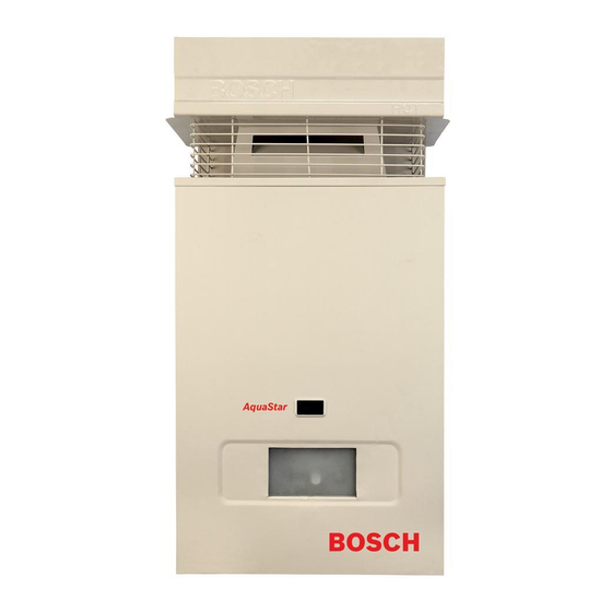
MODEL 125BO LP and 125BO NG - OUTDOOR MODEL
Not approved for space heating purposes
AQ 125 BO NG - Natural Gas
AQ 125 BO LP - Liquefied Petroleum (LP) Gas
Warning: If the information in this manual is not
followed exactly, a fire or explosion may result
causing property damage, personal injury or death.
Do not store or use gasoline or other flammable
vapor and liquids in the vicinity of this or any other
appliance.
Improper
installation,
service or maintenance can cause injury or
property damage. Refer to this manual. For
assistance or additional information consult a
qualified installer, service agency or the gas
supplier.
In the Commonwealth of Massachusetts this
product must be installed by a licensed plumber or
gas fitter.
Upon completion of the installation, these
instructions should be handed to the user of the
appliance for future reference.
For exterior use only
Piezo Ignition
Suitable for heating potable water only
adjustment,
alteration,
What to do if you smell gas
• Close gas valve.
• Do not try to light any appliance.
• Do not touch any electrical switch; do not use any
phone in your building.
• If you cannot reach your gas supplier, call the fire
department.
• Immediately call your gas supplier from a neighbor's
phone. Follow the gas supplier's instructions
• Installation and service must be performed by a
qualified installer, service agency or the gas supplier.
Advertisement
Table of Contents

Related Manuals for Bosch AQ 125BO LP


Summary of Contents for Bosch AQ 125BO LP
- Page 1 MODEL 125BO LP and 125BO NG - OUTDOOR MODEL For exterior use only Piezo Ignition Suitable for heating potable water only Not approved for space heating purposes AQ 125 BO NG - Natural Gas AQ 125 BO LP - Liquefied Petroleum (LP) Gas Warning: If the information in this manual is not What to do if you smell gas followed exactly, a fire or explosion may result...
-
Page 2: Table Of Contents
Index Index Warning Warning Warning: If the information in this Appliance details manual is not followed exactly, a fire or Features explosion may result causing property AQ125 BO specifications (Technical data) damage, personal injury or death. Unpacking the AQ-125-BO heater General rules to follow for safe operation Dimensions and installation clearances Warning:... - Page 3 Warning What to do if you smell gas • Close gas valve. • Do not try to light any appliance. • Do not touch any electrical switch; do not use any phone in your building. • Immediately call your gas supplier from a neighbor’s phone.
-
Page 4: Appliance Details
• Easy Pilot Flame Ignition with push button piezo Gas types ignition. Natural Gas. LP Gas BOSCH is constantly improving its products, therefore specifications are Safety devices subject to change without prior notice. • Flame failure device (ionization flame rod sensor) •... -
Page 5: Unpacking The Aq-125-Bo Heater
Appliance details Unpacking the AQ-125-BO heater any pressure testing at pressures in excess of ½ Psig (3.5 kPa). This heater is packed securely. The appliance and its gas connection must be leak Before installing the unit, be certain you have the tested before placing the appliance in operation. -
Page 6: Dimensions And Installation Clearances
Appliance details Dimensions and installation clearances Fig. 3 Dimensions Fig. 4 Minimum clearances Model AQ125 BO TOP (A) 3 ft. FRONT (B) 4 ft. 0” BACK SIDES 4 ft. 1 ft. BOTTOM (C) Table 1 Minimum clearances 8 716 473 147... -
Page 7: Installation Instructions
Installation instructions Installation instructions Introduction Danger: Flue gases will be released through the vent cap. Flue gas is very Please follow these instructions. Failure to follow hot and contains carbon monoxide. The instructions may result in: heater cannot be installed indoors. To B Damage or injury. -
Page 8: Heater Placement And Clearances
Installation instructions Heater placement and clearances Mounting installation The AQ125 BO is design certified for installation Warning: before starting installation: directly on a combustible wall. (see 3.4 Mounting B check that there are no loose parts installation). For installation on vinyl siding see Fig. 7. inside the appliance Keep the area below the heater free of combustible material. - Page 9 Installation instructions Fig. 7 B Secure heater to wall using enclosed mounting screws. Use mounting template for proper screw location. B Locate head of screw in the key hole of the top mounting bracket. Vent Safety System The AQ125 BO will shut down if the intake or exhaust louvers on the vent cap are blocked for any reason;...
-
Page 10: Gas Piping & Connections
Installation instructions Gas piping & connections Danger: If you have a leak, shut off the gas. Tighten appropriate fittings to stop Before connecting the gas supply, check the rating leak. Turn the gas on and check again plate on the right side of the heater to be sure that the with a gas leak detection solution. - Page 11 Installation instructions FOR NATURAL GAS Maximum Capacity of pipe in Cubic Feet of Gas per Hour for Gas Pressure of 0.5 Psig or less and a Pressure drop of 0.3 in Water Column (0.75mbar).(Based on a 0.60 Specific Gravity Gas) Btu numbers given in thousands. Follow boxed numbers for piping just one AQ125 BO (example: ¾”...
-
Page 12: Measuring Gas Pressure
Installation instructions Measuring gas pressure If the cold and hot connections to the heater are reversed, the heater will not function. Be certain there Connecting manometer are no loose particles or dirt in the piping. Blow out or flush the lines before connecting to the water heater. B Shut off gas. -
Page 13: Electrical Connections
Installation instructions Electrical connections Warning: Confirm that the water heater is appropriately grounded and that the installation meets all electrical codes. Outdoor electrical outlets have special requirements. Warning: safety reasons, disconnect the power supply to the heater before any service or testing is performed. -
Page 14: Operation Instructions
Operation instructions Operation instructions For your safety read before B 8. Observe the pilot flame through the peephole. The gas valve button should be held down for at least 15 operating your water heater seconds with pilot burning. When the gas valve button is released, the pilot should continue to burn. - Page 15 Operation instructions GAS CONTROL SLIDE TEMPERATURE ADJUSTMENT KNOB Fig. 10 Temperature Adjustment Controls Temperature adjustment knob The temperature adjustment knob on the front bottom of the heater (see Fig. 10) adjusts temperature by adjusting flow capacity. See table 4 for details. Knob counter- clockwise...
-
Page 16: Maintenance And Service
Maintenance and service Maintenance and service Maintenance intervals heater is an LP unit, replace orifice. Caution: Do not enlarge orifice. The 125 BO requires periodic maintenance. The below time maintenance intervals should kept the unit Main burners operating for many years. The main burner flames should be blue, with a more Every year intense blue cone in the center core. -
Page 17: Troubleshooting
Troubleshooting Troubleshooting Introduction millivoltage from the thermocouple lead to ground. The expected reading is 24mVDC or greater. Many of the questions customers ask regarding operation of this unit can be answered by follow the Burner do not ignite with water troubleshooting steps as outlined below. -
Page 18: Water Is Too Hot
Troubleshooting • 5. Service water valve See chapter 5.2 for intervals and instructions. • 6. ECO (overheat sensor) tripped due to overheating re-ignite the appliance 10 minutes later. If it happens again, contact your service person. Water is too hot •... -
Page 19: Interior Components And Diagram Parts List
Interior components and diagram parts list Interior components and diagram parts list Interior components Fig. 12 Functional scheme Heat exchanger Water valve Pilot assembly Gas control slide Burner manifold gas pressure test nipple Electronic control box Main gas burner Temperature adjustment selector Pilot gas tubing on/off switch 8 716 473 147... -
Page 20: Components Diagram
Interior components and diagram parts list Components diagram Fig. 13 Components Diagram 8 716 473 147... -
Page 21: Parts List
Interior components and diagram parts list Parts list Item Description Reference Screw 8 716 461 314 Heat exchanger 8 705 406 235 0 Temperature limit 8 707 206 017 0 Hot water pipe 8 716 416 714 Thermocouple 8 707 202 087 0 Burner 8 708 120 298 0 (NG) Burner... -
Page 22: Protecting The Environment
Protecting the environment Protecting the environment Packing The packing box may be fully recycled as confirmed by the recycling symbol Components Many parts in the heater can be fully recycled in the end of the product life. Contact your city authorities for information about the disposal of recyclable products. -
Page 23: Twelve Year Limited Warranty
Aquastar water heaters are warranted by the Manufacturer (BOSCH) through Controlled Energy Note: the water heater must be free of Corp. Controlled Energy Corp. (CEC) will furnish a... - Page 24 Installer Checklist, to be performed by installer upon installation Serial Number ___ ___ ___ ___ ___ ___ ___ ___ (8 digit serial number is located on rating plate on right side panel) Gas Pressure Reading* Static__________ Operating__________ Building Water Pressure __________ Range if on Well system __________ Average Winter Temperature __________...
Need help?
Do you have a question about the AQ 125BO LP and is the answer not in the manual?
Questions and answers