Table of Contents
Advertisement
Quick Links
MODEL 2400 EO - OUTDOOR MODEL
Electronic Ignition and built in Freeze protection
Not approved for space heating purposes
2400 EO NG - Natural Gas
2400 EO LP - Liquefied Petroleum (LP) Gas
Warning: If the information in this manual is not
followed exactly, a fire or explosion may result
causing property damage, personal injury or death.
Do not store or use gasoline or other flammable
vapor and liquids in the vicinity of this or any other
appliance.
Improper
installation,
service or maintenance can cause injury or
property damage. Refer to this manual. For
assistance or additional information consult a
qualified installer, service agency or the gas
supplier.
In the Commonwealth of Massachusetts this
product must be installed by a licensed plumber or
gas fitter.
Upon completion of the installation, these
instructions should be handed to the user of the
appliance for future reference.
For exterior use only
Suitable for heating potable water only
adjustment,
alteration,
What to do if you smell gas
• Close gas valve.
• Do not try to light any appliance.
• Do not touch any electrical switch; do not use any
phone in your building.
• If you cannot reach your gas supplier, call the fire
department.
• Immediately call your gas supplier from a neighbor's
phone. Follow the gas supplier's instructions
• Installation and service must be performed by a
qualified installer, service agency or the gas supplier.
Advertisement
Table of Contents

Related Manuals for Bosch AquaStar 2400 EO


Summary of Contents for Bosch AquaStar 2400 EO
- Page 1 MODEL 2400 EO - OUTDOOR MODEL For exterior use only Electronic Ignition and built in Freeze protection Suitable for heating potable water only Not approved for space heating purposes 2400 EO NG - Natural Gas 2400 EO LP - Liquefied Petroleum (LP) Gas Warning: If the information in this manual is not What to do if you smell gas followed exactly, a fire or explosion may result...
- Page 2 Index Index Warning Warning Warning: If the information in this manual is not followed exactly, a fire or Appliance details Features explosion may result causing property 2400 EO Specifications (Technical data) damage, personal injury or death. Dimensions and Minimum installation clearances General rules to follow for safe operation Proper location for installing your heater Warning:...
- Page 3 Warning What to do if you smell gas • Close gas valve. • Do not try to light any appliance. • Do not touch any electrical switch; do not use any phone in your building. • Immediately call your gas supplier from a neighbor’s phone.
-
Page 4: Appliance Details
• Optional wireless remote control accessory to • Water valve material: Polymer (PPS) (Polypropylene operate with the appliance. Sulfid) BOSCH is constantly improving its • Minimum water flow: 0.8 gallon/minute (3 l/m) products, therefore specifications are • Minimum recommended water pressure: 30 PSI subject to change without prior notice. - Page 5 Appliance details Combustion UNPACKING THE 2400 EO HEATER • NOx ≤ 55 ppm This heater is packed securely. • CO ≤ 250 ppm. The box includes: • Control panel shield Dimensions • Pressure relief valve • Depth (in): 8 ½” (220 mm) •...
-
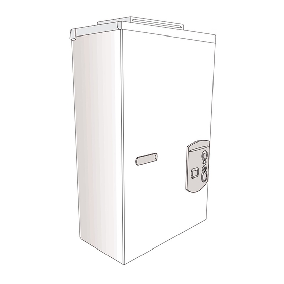
Page 6: Dimensions And Minimum Installation Clearances
Appliance details Dimensions and Minimum installation clearances Fig. 3 Dimensions Cover On/Off switch Reset button LCD display Program button Temperature buttons Fig. 4 Minimum clearances Model 2400 EO TOP (A) 3 ft. FRONT (B) 4 ft. BACK 0” SIDES 4 ft. BOTTOM (C) 1 ft. -
Page 7: General Rules To Follow For Safe Operation
Appliance details General rules to follow for safe WARNING: Proper insulation of the operation water lines below the heater is required if below freezing temperatures, below B 1. You should follow these instructions when you 32°F, are ever anticipated! install your heater. In the United States: The installation must conform with local codes or, in the absence of local codes, the National Fuel Gas Code Danger: If the temperature drops... -
Page 8: Heater Placement And Clearances
Appliance details Heater Placement and Clearances Mounting installation The 2400 EO is design certified for installation directly Warning: before starting installation: on a combustible wall. (see 2.7 Mounting installation) B check that there are no loose parts For installation on vinyl siding see Fig. 10. Keep the area inside the appliance below the heater free of combustible material. - Page 9 Appliance details B After inspection, replace front cover and tighten screws, then replace plastic decal shields. B Fix the top vent cap on the top of the heater, as shown in Fig. 8). Make sure the vent cap is well fitted by taking special care that the front cover stays inside the extended corners of the vent cap, as shown in Fig.
-
Page 10: Gas Piping & Connections
Appliance details Gas piping & connections Warning: The heater must be isolated from the gas supply piping system Before connecting the gas supply, check the rating during any pressure testing of that plate on the right side of the heater to be sure that the system at test pressures equal to or heater is rated for the same gas to which it will be more than 0.5 psig. - Page 11 Appliance details FOR NATURAL GAS Maximum Capacity of pipe in Cubic Feet of Gas per Hour for Gas Pressure of 0.5 Psig or less and a Pressure drop of 0.3 in Water Column (0.75mbar).(Based on a 0.60 Specific Gravity Gas) Btu numbers given in thousands. Follow boxed numbers for piping just one 2400 EO (example: ¾”...
-
Page 12: Measuring Gas Pressure
Appliance details Measuring gas pressure Static Gas Pressure Reading (see Chapter 2.9) enter here: ___________________ 2.9.1 Connecting Manometer B Shut off gas. Operating Gas Pressure Reading (see Chapter 2.9) B Remove front cover and locate inlet gas pressure enter here: ___________________ measuring point (see Fig. -
Page 13: Water Connections
Appliance details 2.10 Water connections lowest pressure range setting recommended is 30-50 psi (2.07 and 3.45bar). When facing the heater, the ¾” cold water inlet is on the bottom right and the hot water outlet is on the bottom Connecting the pressure relief valve (PRV) left. -
Page 14: Electrical Connections
Appliance details 2.11 Electrical connections Warning: The heater is equipped with freeze prevention equipment that will Warning: Confirm that the water operate and prevent freezing of the heater is appropriately grounded and water in the heater to 5°F with no wind that the installation meets all electrical chill. -
Page 15: For Your Safety Read Before Operating Your Water Heater
Appliance details 2.13 For your safety read before NOTE: on a first time initial operating your water heater installation or after gas line work has been done, air in the gas line Warning: If you do not follow these will cause ignition delay when the instructions exactly, a fire or explosion hot water is turned on. -
Page 16: Temperature Selection
Operation instructions Operation instructions Fig. 19 B Press buttons On/Off switch in order to reach Reset button requested temperature. Program button Increasing temperature button Decreasing temperature button LCD display Power B To start the appliance switch the button to the ON position (turn to the right position). - Page 17 Operation instructions Setting the water temperature The desired temperature of the hot water can be adjusted on the front control panel of the heater. The 2400 EO has an electronically controlled gas valve that modulates the burner input in response to both varying hot water flow rates and/or changes in any incoming and outgoing water temperatures.
- Page 18 Operation instructions Use of remote control accessory Fig. 26 Reset button If the problem persists, contact your installer. Program button Fig. 23 Remote control Program button can be used/programmed in the The wireless remote control accessory and the appliance and in the remote control. temperature selector buttons on the front of the water heater operate identically.
-
Page 19: Maintenance And Service
Maintenance and service Maintenance and service BURNERS DO NOT IGNITE WHEN HOT WATER IS Warning: Always turn off the electrical TURNED ON power supply, turn off the manual gas • Cold incoming water connection made to valve and turn off the manual water wrong side of heater control valves whenever servicing. - Page 20 Troubleshooting Test by following 4th bullet under BURNERS DO control of the heater can be lowered to produce a NOT IGNITE WHEN HOT WATER IS TURNED ON. more comfortable hot water temperature. • Inlet water pressure erratic LOW WATER FLOW/PRESSURE fluctuating supply water pressure •...
- Page 21 Troubleshooting Display Cause Solution Temperature limiter opened circuit (overheat). Check connections. * Trips at 220F (104C). Check heat exchanger condition.* No ionization during safety time (safety time out). Check gas pressure. (see chapter Note: appliance makes 3 ignition attempts Check that gas is not diluted with air, as a before entering error mode “EA”.
-
Page 22: Electrical Diagram
Electrical diagram Electrical diagram Fig. 29 Electrical scheme Intlet water temperature sensor Ionization sensor Water flow sensor Over heat protection Temperature limiter Gas valve Water valve AC Plug Ignition electrode Display PCB ON/OFF switch Fuse T 2,5A Fuse T 3,15A Terminal block Ground post Outlet water temperature sensor... - Page 23 2400 EO Functional scheme 2400 EO Functional scheme Fig. 31 Functional scheme 6 720 608 257...
-
Page 24: Interior Components Diagram And Parts List
Interior components diagram and parts list Interior components diagram and parts list Interior components Fig. 32 Components Cover On/Off switch Reset button LCD display Program button Temperature buttons Flue gas collector Mixer Heat exchanger Observation window Inlet air duct Control unit Exhaust fan Water valve Gas valve... -
Page 25: Components Diagram
Interior components diagram and parts list Components diagram 6720607440-08.4 JF Fig. 34 Components Diagram 6 720 608 257... -
Page 26: Parts List
Interior components diagram and parts list Parts list Item Description Reference Front cover 8 705 421 915 Shield 8 705 506 753 Heat exchanger 8 705 406 285 Heat exchanger top gasket 8 704 701 052 Clip 8 716 102 607 Heat exchanger bottom gasket 8 704 701 054 O-ring... - Page 27 Special adjustment for measuring and adjusting CO2 levels Special adjustment for measuring and adjusting CO levels The CO can only be adjusted by a certified gas B. Measuring CO (Cover Installed): technician with a calibrated CO analyzer. B Open hot water taps to achieve a flow rate of at least 4 gallons per minute.
- Page 28 Special adjustment for measuring and adjusting CO2 levels D. Returning to Service: 1. Return slotted cover to original position. 2. Reinstall Torx cover. 3. Remove CO analyzer probe and reinstall plug in exhaust collar. 4. Turn ON/OFF switch to the OFF (O) position and then back to the ON (I) position.
-
Page 29: Protecting The Environment
Protecting the environment Protecting the environment Packing The packing box may be fully recycled as confirmed by the recycling symbol Components Many parts in the heater can be fully recycled in the end of the product life. Contact your city authorities for information about the disposal of recyclable products. -
Page 30: Twelve Year Limited Warranty
Service Labor Costs Aquastar water heaters are warranted by the This warranty does not cover any labor costs Manufacturer (BOSCH) through BBT North America. associated with service, removal or re-installation of BBT North America (BBTNA) will furnish a replacement part(s). All such costs must be borne by the Purchaser. - Page 31 Twelve Year Limited Warranty 6 720 608 257...
- Page 32 Installation manual should be left with the owner after the installation is tested and completed Replacement Parts available from: BBT NORTH AMERICA Bosch Group Bosch Water Heating VULCANO Termodomésticos S.A. 340 Mad River Park Estrada de Cacia Waitsfield, VT 05673...
Need help?
Do you have a question about the AquaStar 2400 EO and is the answer not in the manual?
Questions and answers