Table of Contents
Advertisement
Advertisement
Table of Contents

Related Manuals for K-array KR400S


Summary of Contents for K-array KR400S
- Page 1 KR400S USER MANUAL - english version PRELIMINARY...
- Page 4 PRELIMINARY...
-
Page 5: Table Of Contents
CONTENTS SYMBOLS 1. INTRODUCTION (KL21ma and the KR400S system) 2. APPLICATIONS 3. KEY FEATURES 4. UNPACKING 5. WARRANTY 6. SAFETY 7. PHYSICAL 8. AMPLIFIER 8.1 AC POWER CONNECTOR 8.2 VOLTAGE REQUIREMENT 8.3 CURRENT REQUIREMENT 8.4 REAR PANEL 8.5 POWER CONNECTOR WIRING 8.6 AUDIO INPUT CONNECTOR WIRING... -
Page 6: Symbols
SYMBOLS K-array declares that this device is in compliance with the applicable CE standards and regulations. Before putting the device into operation, please observe the respective country-specific regulations! WEEE Please dispose of this product at the end of its operational lifetime by bringing it to your local collection point or recycling centre for such equipment. - Page 7 PRELIMINARY...
-
Page 8: Introduction (Kl21Ma And The Kr400S System)
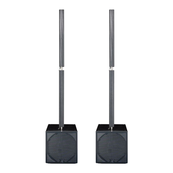
KR400S 1. INTRODUCTION (KL21ma and the KR400S system) The KR400S is a high performance ultra-slim powered two way system designed for small to medium wavefront systems, in both mobile and installed applications. The KR400S includes two KR400 satellites and 2 KL21ma powered subwoofers. -
Page 9: Key Features
God or accidents, or any use of this product that is not in accordance with the instructions provided by K-array. K-array is not liable for consequential damages. This warranty is exclusive and no other warranty is expressed or implied. -
Page 10: Safety
KR400S 6. SAFETY WARNING • It is important that loudspeaker systems are used in a safe manner. • Professional loudspeakers are capable of producing extremely high sound levels and should be used with care. Hearing loss is cumulative and can result from levels above 90dB if people are exposed for an extended period. -
Page 11: Physical
KR400S 7. PHYSICAL KL21ma 55.5 cm 21.85” 55.5 cm 21.85” 77.7 cm 30.60” weight: 39 kg (86 lbs) 77.7 cm 30.60” 55.5 cm 55.5 cm 21.85” 21.85” 77.7 cm 30.60” PRELIMINARY... - Page 12 KR400S KR400 100.5 cm 205.2 cm 39.57” 80.90” 8.8 cm 3.56” 100.5 cm 39.57” 265 cm 19.88” 11.5 cm 4.53” 8.8 cm 3.56” 11.5 cm 8.8 cm 4.53” 3.56” weight: 2 X 9 kg (2 x 19.84 lbs) weight: 57 kg (152.66 lbs)
-
Page 13: Amplifier
Before applying AC to any K-array self-powered speaker, be sure that the voltage potential difference between neutral and earth ground is less than 5 VAC. -
Page 14: Rear Panel
For best performance, the AC Cable voltage drop should not exceed 10% at 115V and 5% at 230V. The minimum electrical service amperage required by a K-array loudspeakers system is the sum of their maximum continuous RMS current. We recommend allowing an additional 30% above the minimum amperage to prevent peak voltage drops at the service entry. -
Page 15: Power Connector Wiring
KR400S 8.5 POWER CONNECTOR WIRING The KL21ma’s amplifiers receive DC power from the 3-pin blue PowerCon connector on their back panel. The white PowerCon connector is a parallel OUTPUT for supplying power to other devices (max 5A @110V supported). When AC power is applied to the speaker, the auto-range power supply automatically selects the correct operating voltage. -
Page 16: Amplification And Protection Circuitry
KR400S 8.7 AMPLIFICATION AND PROTECTION CIRCUITRY The KL21ma is powered by a 2-channel high power digital amplifier feeding the connected KR400 modules with a power output of 1800W in each channel. All the specific functions for the KL21ma, such as crossovers, frequency, phase response, and driver protection are determined by a DSP processor installed inside the amplifier. -
Page 17: System Configuration On The Floor
KR400S 9. SYSTEM CONFIGURATION ON THE FLOOR PRELIMINARY... - Page 18 KR400S PRELIMINARY...
- Page 19 KR400S PRELIMINARY...
- Page 20 KR400S Speakon power OUT PRELIMINARY...
- Page 21 KR400S The included joints allow the user to tilt both the KR400 modules at different angles (positive and negative) in order to cover different audience areas. Some examples of typical configurations: PRELIMINARY...
- Page 22 KR400S PRELIMINARY...
- Page 23 KR400S PRELIMINARY...
- Page 24 KR400S PRELIMINARY...
-
Page 25: Hanging Installation Instructions
KR400S 10. HANGING INSTALLATION INSTRUCTIONS PRELIMINARY... - Page 26 KR400S PRELIMINARY...
- Page 27 KR400S Set to max 5° for the three upper frames. PRELIMINARY...
-
Page 28: Dsp Control & Remote Control
KR400S 10. DSP CONTROL & REMOTE CONTROL KL21ma has a powerful DSP that manages all the functions of the speakers. Each system can store 16 presets on board that can be recalled by pushing the PRESET button. Once the preset appears on the lower line of the display, it will automatically become available after a few seconds. -
Page 29: Cloner Function & Preset Systems
The preset heve been cloned to Speaker B. 11. REMOTE CONTROL SOFTWARE 1 . To connect the K-array modules to a PC, a RS485-USB adapter is required, we recommend the K-USB adapter (pic.1). Connect the K-USB to a PC and install the required drivers included in the CD-ROM. - Page 30 KR400S 2. Install the K array control software from the CD-ROM installer. 2.1. Start the Karray_manager_V2 from Windows (Start -Software -Karray managerV2) 2.2.Click on NO when asked whenether you want to star in Demo Mode. 2.3.Click onSystem-Settings to configure which COM port use. The COM port of K-USB is usually the highest number.
- Page 31 KR400S 3 . IDsetting Address x 10 Address x 1 Preset scroll Address for remote control Preset loaded From pc or previous module To next module By pressing this button you can re- fresh the modules connected. On these bars you can see all the modules connected to your chain.
- Page 32 KR400S 4 .Single module control Click once on the ID module that you want to control. This frame describes the state of all the loudspeakers on the chain. The colour of the little rectangles in this frame represents the status of the loudspeakers.
- Page 33 KR400S Preset slots on the module Module status panel With this button, you can load presets from the PC to the module. Click on this button, choose the slot that you want use and select the EQS file that you want to load.
- Page 34 KR400S 5.Mute groups On the Mute Groups window, you can mute the modules as groups. You can have up to 4 different groups. 5.1.Choose the modules from the list on the right and press the right arrow button next to the group that you wish to use to add the modules.
- Page 35 KR400S 6.2. It is possible to assign names to the groups, by simply writing in the fields. PRELIMINARY...
- Page 36 KR400S 6.3. From the Preset Send window you can load a preset on the same slot of multiple devices. PRELIMINARY...
- Page 37 KR400S 7. Text editor It is available a text editor on the software, it can manage .RTF files. 8.Master Mute control It is possible to Mute all the modules connected by pressing the Master Mute button. The button is locked to prevent it from being accidentally. You will need to Unlock it by pressing the Unlock button below it.
-
Page 38: Presets Diagrams
KR400S 12. PRESETS DIAGRAMS eaClear eaC-3 eaC-6 PRELIMINARY... - Page 39 KR400S eaC-3Hi eaC+3Hi eaC-3Lo PRELIMINARY...
- Page 40 KR400S eaC-6Sub PRELIMINARY...
-
Page 41: Service
13. SERVICE To obtain service: 1) Contact the official K-array distributor in your country. They will direct you to the service centre. 2) If you are calling for service, have the serial number(s) of the unit(s) to hand for refe- rence. -
Page 42: Kr400S Technical Details
KR400S 14. KR400s TECHNICAL DETAILS KR400S Acoustics Power handling 1500(sub) + 2 x 720(sat) w (EAS) Maximum 2500(sub) + 2 x 1200(sat) w (EIAJ) amplifier power Impedance 4Ω(sub)+6Ω(sat) Operating 30Hz - 19 KHz +/- 3dB (preset dependent) frequency range Maximum SPL... - Page 43 APPROVAL K-array declares that this device is in compliance with the applicable CE standards and regulations. Before putting the device into operation, please observe the respective country-specific regulations! WEEE Please dispose of this product at the end of its operational lifetime by bringing it to your local collection point or recycling centre for such equipment.
- Page 44 HP Sound Equipment s.r.l. Viale Roma 7/i - 50037 San Piero a Sieve (Firenze) - Italy tel. +39 055 8487222 - fax. +39 0558487238 e-mail: info@k-array.com www.k-array.com PRELIMINARY...
Need help?
Do you have a question about the KR400S and is the answer not in the manual?
Questions and answers