Bosch D9412GV2 Operation And Installation Manual
Hide thumbs
Also See for D9412GV2:
- Program entry manual (148 pages) ,
- Troubleshooting manual (134 pages) ,
- Owner's manual supplement (20 pages)
Table of Contents
Advertisement
Quick Links
Advertisement
Chapters
Table of Contents

Related Manuals for Bosch D9412GV2


Summary of Contents for Bosch D9412GV2
- Page 1 D9412GV2/D7412GV2 Operation and Installation Guide Control Panels...
-
Page 2: Listings And Approvals
D9412GV2/D7412GV2 | Operation and Installation Guide | Trademarks Trademarks Federal Communications Commission (FCC) Rules CoBox is a registered trademark of Lantronix. Windows is a registered trademark of Microsoft Part 15 Corporation in the United States or in other countries. This equipment was tested and found to comply with... - Page 3 D9412GV2/D7412GV2 | Operation and Installation Guide | Federal Communications Commission (FCC) Rules If the D9412GV2 or D7412GV2 Control Panel causes harm to the telephone network, the telephone company attempts to notify you in advance. If advance notice is not practical, the telephone company notifies you as soon as possible.
-
Page 4: Table Of Contents
D9412GV2/D7412GV2 | Operation and Installation Guide | Contents Installing the Point Chart Label ....19 Contents Testing the System ........19 4.10 Service Walk Test ........20 Introduction..........7 Power Supply ..........23 Lightning Strikes .........8 Primary Power Terminals 1 and 2 ....23 Effects............8... - Page 5 D9412GV2/D7412GV2 | Operation and Installation Guide | Contents Wiring Information for Installations Using 11.3 D279A Independent Zone Control ....60 the Rothenbuhler 5110/4001-42 High 11.4 Keyswitch ............ 60 Security Bell..........36 11.4.1 Description ..........60 Off-Board Points........39 11.4.2 Programming..........60 Point (Zonex) Bus: D9412GV2 Terminals 11.4.3 Installation ...........
- Page 6 D9412GV2/D7412GV2 | Operation and Installation Guide | Contents Figure 35: Programmer and Accessory Figures Connections.......... 66 Figure 1: System Configuration......9 Figure 36: D9412GV2 Faceplate......67 Figure 2: Enclosure Mounting ......15 Figure 37: D7412GV2 Faceplate......68 Figure 3: Ground Fault Detection......16 Figure 38: D9412GV2, Power Supply Side ...
-
Page 7: Introduction
This manual addresses the operation and installation of the D9412GV2 and D7412GV2 Control Panels. Throughout this guide, the words “control panel” refer to both control panels (D9412GV2 and D7412GV2). Table 2 on page 9 provides an overview of the differences in the control panels. -
Page 8: Lightning Strikes
D9412GV2/D7412GV2 | Operation and Installation Guide | 2.0 Lightning Strikes 2.0 Lightning Strikes The control panels are designed to significantly reduce electromagnetic interference and malfunction generally caused by lightning. Effects Any electronic system can be struck directly by lightning or be adversely affected by a lightning strike near the system. -
Page 9: Overview
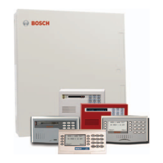
D9412GV2/D7412GV2 | Operation and Installation Guide | 3.0 Overview 3.0 Overview Configuration and Parts Figure 1: System Configuration D8129 OctoRelay pr ovides alarm D9210B Modules can be and auxiliary relay output. used for access control. (Other functions available.) Each D8128D OctoPOPIT combines DX4020 allows communciation eight POPIT points in one module. -
Page 10: Parts List
D9412GV2 and D7412GV2. available in hard copy only (P/N: F01U011024), CD-ROM only (P/N: F01U012325), or hard copy with enclosed CD-ROM (P/N: F01U012326). Accessories Refer to the Bosch Security Systems, Inc. product catalog for additional information. Table 3: Compatible Accessories Model Title... -
Page 11: Sdi Molex Connector
D9412GV2/D7412GV2 | Operation and Installation Guide | 3.0 Overview Table 3: Compatible Accessories (continued) Model Title UL 864 Fire Intrusion D1255W Text Keypad (white) D1256 Fire Keypad (Command Center) D1257 Fire Alarm Annunciator D1260/D1260B Keypads D1640 16.5 VAC 40 VA Transformer... -
Page 12: Telephone Line Sniff
D9412GV2/D7412GV2 | Operation and Installation Guide | 3.0 Overview Plan to replace the lithium battery after 3 to 5 years of 3.3.4 Telephone Line Sniff continual service. The D9412GV2 and D7412GV2 control panels When replacing the lithium battery, monitor the phone line for the programmed... -
Page 13: Keypads
D9412GV2/D7412GV2 | Operation and Installation Guide | 3.0 Overview Table 4: Software Version Compatibility of Table 5: Compatible Keypads and Command D6500 MPU and Line Cards Centers Line Card Software Version Model Display Application D6510 8.00 and higher D1255/ 16-character... -
Page 14: Event Log
D9412GV2/D7412GV2 | Operation and Installation Guide | 3.0 Overview 3.3.12 Event Log 3.3.16 Programming The system stores from 500 to 1000 events and event Use the Bosch Security Systems D5200 Programmer modifiers from all areas in its event log. Event or the Remote Programming Software (RPS) to modifiers add information about an event to the log. -
Page 15: Installation
D9412GV2/D7412GV2 | Operation and Installation Guide | 4.0 Installation Enclosure Options 4.0 Installation Mount the control panel assembly in any of the Bosch Security Systems, Inc. enclosures listed: Installation Preparation • D8103 Universal Enclosure (tan) This section contains a general installation procedure •... -
Page 16: Installing The Control Panel
D9412GV2/D7412GV2 | Operation and Installation Guide | 4.0 Installation • If a ground fault condition occurs, the keypads Installing the Control Panel display SERVC GND FAULT and the control 1. Place the control panel over the inside back of the... -
Page 17: Enabling Ground Fault Detection
ZONEX OUT 2 RELAY B be provided with this equipment. SWITCHED AUX D9412GV2 Control Panel is UL Listed For Central Station, Local, Auxiliary, Proprietary, and Terminal Household Fire Alarm, and Central Station, Local, Police Station Connect, Household Burglar Alarm ZONEX IN 2 RELAY C and Encrypted Line Security when communicating via a network. -
Page 18: Locking The Reset Pin
D9412GV2/D7412GV2 | Operation and Installation Guide | 4.0 Installation 4.5.5 Locking the Reset Pin Completing the Installation Locking the reset pin disables the control panel If not already complete, make the earth ground (Figure 6). When the control panel is disabled, the connection to Terminal 10 and lock the reset pin in system ignores the keypads and points. -
Page 19: Installing Modules And Relays
D9412GV2/D7412GV2 | Operation and Installation Guide | 4.0 Installation 4.6.3 Installing Modules and Relays Programming the Control Panel Power down the unit by unplugging the If the control panel is not already programmed, review transformer and disconnecting the battery. the D9412GV2/D7412GV2 Program Entry Guide Always power down the unit when (P/N: F01U003636). -
Page 20: Service Walk Test
D9412GV2/D7412GV2 | Operation and Installation Guide | 4.0 Installation 4.10 Service Walk Test The D7412GV2 does not include the Service Walk Test in the Service Menu. The Service Walk Test differs from the standard Walk Enabling the Service Walk Test function Test. -
Page 21: Figure 7: D9412Gv2 Service Walk Test Flow Chart
D9412GV2/D7412GV2 | Operation and Installation Guide | 4.0 Installation Figure 7: D9412GV2 Service Walk Test Flow Chart SERVICE WALK? [ENT] 246 PTS TO TEST [ESC] Test a device POINT TEXT (Text displays for 60 seconds) 245 PTS TO TEST [ESC]... -
Page 22: Figure 8: D7412Gv2 Service Walk Test Flow Chart
D9412GV2/D7412GV2 | Operation and Installation Guide | 4.0 Installation Figure 8: D7412GV2 Service Walk Test Flow Chart SERVICE WALK? [ENT] 75 PTS TO TEST [ESC] Test a device POINT TEXT (Text displays for 60 seconds) 74 PTS TO TEST [ESC]... -
Page 23: Power Supply
D9412GV2/D7412GV2 | Operation and Installation Guide | 5.0 Power Supply 4. Plug the transformer into an unswitched, 120 5.0 Power Supply VAC, 60 Hz power outlet only. Primary Power Terminals 1 and 2 5. Secure the transformer to the outlet with the screw provided. -
Page 24: Installing The Battery
D9412GV2/D7412GV2 | Operation and Installation Guide | 5.0 Power Supply UL 864 Battery Requirements Warning: High current arcs are possible. The positive (red) battery lead and If two batteries are needed to meet the standby time Terminal 5 can create high current arcs if... -
Page 25: Figure 9: Non-Power-Limited Wiring
D9412GV2/D7412GV2 | Operation and Installation Guide | 5.0 Power Supply Figure 9: Non-Power-Limited Wiring + AUX BATTERY NEGATI Maximum Charging Current 1.4 Amps. BATTERY POSITIVE ONLY PROGRAMMABLE RELAY A ALARM OUTPUTS Terminals & RELAY B Requires Optional D136 Relay In ALT ALARM RELAY C &... -
Page 26: Replacing The Battery
D9412GV2/D7412GV2 | Operation and Installation Guide | 5.0 Power Supply 5.2.3 Replacing the Battery Figure 10: Charging and Battery LEDs Replace batteries every 3 to 5 years under normal use. Record the date of installation directly on the battery. LEDs Off When Normal... -
Page 27: Battery Discharge And Recharge Schedule
D9412GV2/D7412GV2 | Operation and Installation Guide | 5.0 Power Supply 5.2.6 Battery Discharge and Recharge Schedule Overcharge Load Shed With AC Present: If more than 1.4 A of auxiliary current draw from the control Table 7: Battery Discharge and Recharge... -
Page 28: Power Outputs
D9412GV2/D7412GV2 | Operation and Installation Guide | 6.0 Power Outputs Terminal 32 – SDI Power +: Use this terminal to 6.0 Power Outputs power serial device interface (SDI) devices such as keypads, the D9131A Parallel Printer Interface Circuit Protection Module, and the D9210B Wiegand Control Interface Module. -
Page 29: Terminals 6 And 7
D9412GV2/D7412GV2 | Operation and Installation Guide | 6.0 Power Outputs Voltage Output at Terminals 6, 7, and 8 6.4.3 Fire System Power Formula If Terminals 6, 7, and 8 do not provide the expected To calculate the current available at Terminals 6 and... -
Page 30: Telephone Connections
D9412GV2/D7412GV2 | Operation and Installation Guide | 7.0 Telephone Connections Figure 11: RJ31X Wiring 7.0 Telephone Connections Registration RJ31X RING (red) TIP (green) The Bosch Security Systems, Inc. D9412GV2 and D7412GV2 Control Panels are registered with the Federal Communication Commission (FCC) under... -
Page 31: Phone Led (Red)
D9412GV2/D7412GV2 | Operation and Installation Guide | 7.0 Telephone Connections Any time the control panel uses the telephone line to Phone LED (Red) make a call or is on-line with the remote programming The red Phone LED illuminates when the control... -
Page 32: D928 Dual Phone Line Switcher
D9412GV2/D7412GV2 | Operation and Installation Guide | 7.0 Telephone Connections Enhanced Communication 7.11 D928 Dual Phone Line Switcher The D9412GV2 and D7412GV2 Control Panels can 7.11.1 Description send events over the SDI Bus to a DX4020 or The optional D928 Dual Phone Line Switcher allows D9133TTL-E Network Interface Module (NIM). -
Page 33: Installing The D928
D9412GV2/D7412GV2 | Operation and Installation Guide | 7.0 Telephone Connections 7.11.3 Installing the D928 Figure 13: D928 Dual Phone Line Switcher Mounting Mount the D928 on the lower right side of the enclosure using the screws provided with the switcher. - Page 34 D9412GV2/D7412GV2 | Operation and Installation Guide | 7.0 Telephone Connections Phone Line Fail LEDs Two yellow Phone Line Status LEDs (one for the primary telephone line, one for the secondary telephone line) light if the telephone line is not within the operating range.
-
Page 35: On-Board Points
D9412GV2/D7412GV2 | Operation and Installation Guide | 8.0 On-Board Points The number of normally-open and normally-closed 8.0 On-Board Points detection devices each sensor loop can supervise is limited only by the resistance on the loop. The total Terminals 11 to 22 Description resistance for the wire length and contacts, minus the end-of-line (EOL) resistor, must not exceed 100 Ω. -
Page 36: Point Response Time
D9412GV2/D7412GV2 | Operation and Installation Guide | 8.0 On-Board Points Point Response Time Wiring Information for Installations Using the Rothenbuhler The control panel scans on-board and off-board point 5110/4001-42 High Security Bell sensor loops every 300 ms. The Debounce program... -
Page 37: Security Bell Wiring Configuration
D9412GV2/D7412GV2 | Operation and Installation Guide | 8.0 On-Board Points Figure 15: Rothenbuhler 5110/4001-42 High Security Bell Wiring Configuration 0.64 mm (1/4 in.) minimum distance 1 - Self-contained vibration sensor 10 - D126 Battery 2 - Control panel 11 - D8108A Enclosure... -
Page 38: Figure 16: Wiring The Rothenbuhler 5110/4001-42
D9412GV2/D7412GV2 | Operation and Installation Guide | 8.0 On-Board Points Figure 16: Wiring the Rothenbuhler 5110/4001-42 High Security Bell to the D9412GV2 or D7412GV2 Control Panel RE D B L K 1 2 3 N/O 1 COMM 1 N/C 1... -
Page 39: Off-Board Points
D9412GV2/D7412GV2 | Operation and Installation Guide | 9.0 Off-Board Points Table 11: POPEX Modules 9.0 Off-Board Points Point (Zonex) Bus: D9412GV2 Model Power Data Terminals and D7412GV2 D9412G Terminals 23 and 24 Terminals 25 and 26 Terminals Terminals 27 and 28 9.1.1... -
Page 40: D9412Gv2/D7412Gv2 Responses To Missing Point Conditions
D9412GV2/D7412GV2 | Operation and Installation Guide | 9.0 Off-Board Points Table 13: Off-Board Point Errors Error Condition Result Additional Information +/- leg of the data expansion bus has a Ground Fault event short circuit to earth ground, with Ground Fault Detect enabled... -
Page 41: Figure 17: Connecting The D8125 Popex To The D9412Gv2 Control Panel
D9412GV2/D7412GV2 | Operation and Installation Guide | 9.0 Off-Board Points Figure 17: Connecting the D8125 POPEX to the D9412GV2 Control Panel Reset Pin Disable All Except Battery Charging And Programming PERIPHERAL DEVICE CONNECTIONS POWER + D9127U/T D9127U/T D9127U/T YELLOW DATA BUS A... -
Page 42: Figure 18: Connecting The D8125 Popex To The D7412Gv2 Control Panel
D9412GV2/D7412GV2 | Operation and Installation Guide | 9.0 Off-Board Points Figure 18: Connecting the D8125 POPEX to the D7412GV2 Control Panel Low Battery Battery D9127U/T D9127U/T D9127U/T amming E CONNECTIONS CLASS 2 TRANS POWER + 16.5 VAC 40 VAC Model D1640... -
Page 43: Installing The D8125 Popex Module
Refer to Section 9.3.6 POPIT Module Point and D7212GV2. The other set is marked “Bank 2” for Assignments on page 44. use with the D9412GV2 and D9112. Use the sheets Review Section 4.6.2 Installing and Wiring Detection later to label the POPITs. Refer to Section 9.3.6 Devices on page 18 to determine if shielded wire is POPIT Module Point Assignments on page 45. -
Page 44: Wiring Data Expansion Loops To Popex Modules
D9412GV2/D7412GV2 | Operation and Installation Guide | 9.0 Off-Board Points Three-inch Clearance for Tampered POPITs 9.3.6 POPIT Module Point Assignments Mount tampered POPIT modules at least 7.6 cm (3 Six switches on each POPIT assign the module to a in.) apart to prevent the tamper magnets from... -
Page 45: Popit Labels
Intrusion Alarm Systems in the and 129 to 247. The D7412GV2 uses Points 9 to 75 D9412GV2/D7412GV2 Approved only. The D9412GV2 reserves Points 128 and 248 for Applications Compliance Guide internal use. POPITs must be connected for Points (P/N: F01U003639) for important... -
Page 46: Listings
D9412GV2/D7412GV2 | Operation and Installation Guide | 9.0 Off-Board Points 9.4.2 Listings Figure 20: D8128D OctoPOPIT Layout The D8128D OctoPOPIT Module is UL Listed for Local or Police Connected Burglary Alarm, Central Station Burglary Alarm, Household Burglary Alarm applications, and commercial fire applications (UL 864 and NFPA 72). -
Page 47: Installation
D9412GV2/D7412GV2 | Operation and Installation Guide | 9.0 Off-Board Points 9.4.3 Installation Table 15: D8128D OctoPOPIT Switch Settings For the most effective installation, use the following for D9412GV2 and D7412GV2 four-step process: 1. Set the OctoPOPIT switches. Refer to Section... -
Page 48: Mounting Octopopits
D9412GV2/D7412GV2 | Operation and Installation Guide | 9.0 Off-Board Points Point DIP Switches 9.4.6 Wiring OctoPOPITs Each point connected to the D8128D is enabled by Warning: Disconnect all power to the closing the respective DIP switch, or disabled by control panel before beginning any work opening the DIP switch. -
Page 49: Figure 21: Connecting D8128D Octopopits To The D9412Gv2
D9412GV2/D7412GV2 | Operation and Installation Guide | 9.0 Off-Board Points Figure 21: Connecting D8128D OctoPOPITs to the D9412GV2 Reset Pin Disable All Except Battery Charging And Programming PERIPHERAL DEVICE CONNECTIONS POWER + YELLOW DATA BUS A GREEN DATA BUS B... -
Page 50: Figure 22: Connecting D8128D Octopopits To The D7412Gv2
D9412GV2/D7412GV2 | Operation and Installation Guide | 9.0 Off-Board Points Figure 22: Connecting D8128D OctoPOPITs to the D7412GV2 Battery amming E CONNECTIONS POWER + DATA BUS A DATA BUS B COMMON ZONEX OUT 1 ZONEX IN 1 NOT USED NOT USED... -
Page 51: Octopopit Sensor Loops
1 k t h a 1 k h a 1 k a 1 k a 1 k D9412GV2/D7412GV2 | Operation and Installation Guide | 9.0 Off-Board Points ® Using Molex Connectors Each D8128D Module is supplied with a 30 cm (12 in.) female-to-female Molex cable assembly. -
Page 52: Testing Off-Board Points
D9412GV2/D7412GV2 | Operation and Installation Guide | 9.0 Off-Board Points Figure 24: D8128D OctoPOPIT Sensor Loops COM IN OUT+12V P1 COM P2 P3 COM P4 P5 COM P6 P7 COM P8 1 - D8128D OctoPOPIT 2 - To control panel... -
Page 53: Off-Board Relays
D9412GV2/D7412GV2 | Operation and Installation Guide | 10.0 Off-Board Relays Alarm output, auxiliary relay, sensor reset, arming 10.0 Off-Board Relays status, point status, alarm memory, or remote functions can be assigned to the OctoRelay outputs 10.1 D8129 OctoRelay individually. Refer to Relay Parameters in the... -
Page 54: Configuring The D8129 Octorelay
D9412GV2/D7412GV2 | Operation and Installation Guide | 10.0 Off-Board Relays Figure 26: D8129 Connections to the D7412GV2 Battery amming E CONNECTIONS POWER + DATA BUS A DATA BUS B COMMON ZONEX OUT 1 ZONEX IN 1 NOT USED NOT USED... -
Page 55: Wiring Connections
D9412GV2/D7412GV2 | Operation and Installation Guide | 10.0 Off-Board Relays To install OctoRelays in the enclosure with the control Table 19: Number of D8128Ds Used with panel: D8129s 1. Align the module with one of the mounting locations in the enclosure (refer to Figure 2 on... -
Page 56: Installation
D9412GV2/D7412GV2 | Operation and Installation Guide | 10.0 Off-Board Relays 10.2.2 Installation 10.2.3 Wiring Connections Install the D811 in the enclosure with the control Power down the control panel to connect D811 panel (Figure 27) or in an adjacent enclosure no more... -
Page 57: Figure 28: D811 Module Wiring To The
D9412GV2/D7412GV2 | Operation and Installation Guide | 10.0 Off-Board Relays Figure 28: D811 Module Wiring to the D7412GV2 Battery amming E CONNECTIONS POWER + DATA BUS A DATA BUS B COMMON ZONEX OUT 1 ZONEX IN 1 NOT USED DATA... -
Page 58: Arming Devices
D9412GV2/D7412GV2 | Operation and Installation Guide | 11.0 Arming Devices • D720/D720B LED display keypad appropriate 11.0 Arming Devices for use as a single area keypad with up to eight points. 11.1 Description D1255 and D720 are available in white... -
Page 59: Installation
D9412GV2/D7412GV2 | Operation and Installation Guide | 11.0 Arming Devices 11.2.2 Installation Extra Power for More Keypads Refer to the keypad installation manuals for The D1255 and D1255B Keypads draw 104 mA when installation and mounting instructions. Keypads idle. They draw 206 mA with the keys lit and the connect to the control panel in parallel (Table 21). -
Page 60: D279A Independent Zone Control
D9412GV2/D7412GV2 | Operation and Installation Guide | 11.0 Arming Devices Figure 29: Power at Keypads 1 - To control panel 4 - Common 2 - +12 VDC 5 - D8132 or external power supply 3 - Data For momentary keyswitches, connect the EOL 11.3... -
Page 61: Figure 30: Keyswitch Wiring
D9412GV2/D7412GV2 | Operation and Installation Guide | 11.0 Arming Devices Figure 30: Keyswitch Wiring ∗ 1 - Maintained keyswitch 5 - 1 kΩ or 33 kΩ resistor 2 - Momentary keyswitch Open on a circuit arms the area 3 - Common... -
Page 62: Sdi Devices
D9412GV2/D7412GV2 | Operation and Installation Guide | 12.0 SDI Devices 12.3 D9131A Parallel Printer Interface 12.0 SDI Devices Module The Bosch Security Systems, Inc. D9131A Parallel 12.1 Description Printer Interface Module is a four-wire powered device D9412GV2 and D7412GV2 Control Panels can... -
Page 63: D9210B Wiegand Control Interface Module
D9412GV2/D7412GV2 | Operation and Installation Guide | 12.0 SDI Devices If an SDI device is supervised and Terminal SDI A Table 24: Address Switch Settings for becomes disconnected, the device can continue to Access Control Module operate normally, depending upon environmental conditions. -
Page 64: Supervision
D9412GV2/D7412GV2 | Operation and Installation Guide | 12.0 SDI Devices 12.6.1 D9133DC Direct Connect Programming Figure 31: D9133 Jumper Setting for Address Module Use the D9133DC Direct Connect Programming Module to handle local programming of the D9412GV2 and D7412GV2 Control Panels. In addition, the D9133DC allows diagnostic and history retrieval. -
Page 65: Address Settings
D9412GV2/D7412GV2 | Operation and Installation Guide | 12.0 SDI Devices 12.6.3 Address Settings The DX4020 has specific DIP switch settings for SDI Address 88 when using the DX4020 for Remote Programming Software (RPS) or enhanced communications in a local-area network (LAN) or wide-area network (WAN) environment. -
Page 66: Programmer And Accessory Connections
D9412GV2/D7412GV2 | Operation and Installation Guide | 13.0 Programmer and Accessory Connections 13.3 Accessory Connector 13.0 Programmer and Use the accessory connector to connect the control Accessory Connections panel to the D928 Dual Phone Line Switcher. The accessory connector is on the bottom right corner of 13.1... -
Page 67: Faceplates
ZONEX OUT 2 RELAY B be provided with this equipment. SWITCHED AUX D9412GV2 Control Panel is UL Listed For Central Station, Local, Auxiliary, Proprietary, and Terminal ZONEX IN 2 RELAY C Household Fire Alarm, and Central Station, Local, Police Station Connect, Household Burglar Alarm and Encrypted Line Security when communicating via a network. -
Page 68: D7412Gv2 Faceplate
Minimum system requirements for Classification in accordance with ANSI/SIA CP-01-2000: Disable All Except Battery UL Listed and Classified control unit Model D9412GV2, D7412GV2, or D7212GV2; 10.2 VDC - Battery Load Shed UL Listed and Classified keypad Model D1256, D1257, D1260, D1255, D1255R, or D1255RW;... -
Page 69: Appendix A: System Wiring Diagrams, Issue A
D9412GV2/D7412GV2 | Operation and Installation Guide | Appendix A: System Wiring Diagrams, Issue A Appendix A: System Wiring Diagrams, Issue A D9412GV2 Control Panel Figure 38: D9412GV2, Power Supply Side D113 BAT 2 - CHGR- BAT 2+ VAU X+ BAT 1-... -
Page 70: Figure 39: D9412Gv2, Input Points And Peripheral Devices
D9412GV2/D7412GV2 | Operation and Installation Guide | Appendix A: System Wiring Diagrams, Issue A Figure 39: D9412GV2, Input Points and Peripheral Devices CLASS 2 TRANSFORMER 16.5 VAC 40 VA 60 Hz Model D1640 Internally Fused - Do Not short Requires Unswitched Outlet... -
Page 71: Figure 40: D9412Gv2, Sdi Devices
D9412GV2/D7412GV2 | Operation and Installation Guide | Appendix A: System Wiring Diagrams, Issue A Figure 40: D9412GV2, SDI Devices D9412GV2 PERIPHERAL DEVICE CONNECTIONS POWER + YELLOW DATA BUS A GREEN DATA BUS B BLACK COMMON N.F.P.A. ZONEX OUT 1 Style 3.5... -
Page 72: D7412Gv2 Control Panel
D9412GV2/D7412GV2 | Operation and Installation Guide | Appendix A: System Wiring Diagrams, Issue A D7412GV2 Control Panel Figure 41: D7412GV2, Power Supply Side BAT 2- CHGR- B AT 2+ VAUX+ B AT 1- S UPV BAT 1+ CHGR+ CLASS 2 TRANSF O RMER 1 6 . -
Page 73: Figure 42: D7412Gv2, Input Points And Peripheral Devices
D9412GV2/D7412GV2 | Operation and Installation Guide | Appendix A: System Wiring Diagrams, Issue A Figure 42: D7412GV2, Input Points and Peripheral Devices CLASS 2 TRANSFORMER 16.5 VAC 40 VA 60 Hz Model D1640 Internally Fused - Do Not short Requires Unswitched Outlet... -
Page 74: Figure 43: D7412Gv2, Sdi Devices
D9412GV2/D7412GV2 | Operation and Installation Guide | Appendix A: System Wiring Diagrams, Issue A Figure 43: D7412GV2, SDI Devices D7412GV2 PERIPHERAL DEVICE CONNECTIONS PERIPHERAL DEVICE CONNECTIONS POWER + POWER + YELLOW DATA BUS A YELLOW DATA BUS A GREEN DATA BUS B... -
Page 75: Appendix B: Point Address Charts
D9412GV2/D7412GV2 | Operation and Installation Guide | Appendix B: Point Address Charts Appendix B: Point Address Charts Zonex 1, Points 9 to 127 (D9412GV2); Zonex 1, Points 9 to 75 (D7412GV2) Place the labels on the base of the POPIT. Do not attach labels to the POPIT cover. -
Page 76: Zonex 2, Points 129 To 247 (D9412Gv2 Only)
D9412GV2/D7412GV2 | Operation and Installation Guide | Appendix B: Point Address Charts Zonex 2, Points 129 to 247 (D9412GV2 Only) Place the labels on the base of the POPIT. Do not attach labels to the POPIT cover. A number in the switch column indicates that the switch is set to ON. -
Page 77: Specifications
Current Control Panel: Idle 225 mA; Alarm 300 mA Requirements Refer to the Current Rating Chart for Standby Battery Calculations section in the D9412GV2/D7412GV2 Approved Applications Compliance Guide (P/N: F01U003639) for the current draw requirements of other system components. Power All external connections are power-limited except battery terminals. - Page 78 Bosch Security Systems, Inc. 130 Perinton Parkway Fairport, NY 14450-9199 www.boschsecurity.com © 2009 Bosch Security Systems, Inc. F01U003641-04...
- Page 79 D1255/D1255B Installation Instructions Keypads...
- Page 80 You can program the control panel to generate The D1255/D1255B Keypad is an SDI Bus compatible messages to the Central Station identifying the device used with Bosch Security Systems control supervised keypad that is in trouble. If a keypad loses panels. The D1255/D1255B features a keypad that...
-
Page 81: Digital Keypad
When you activate the Watch feature, an functions available, consult the following Tone intermittent beep tone (the same as the Entrance Warning Signal) alerts the user documentation: anytime a watch point is faulted. This option is programmable by point. Bosch Security Systems | 8/04 | 74-06819-000-F... - Page 82 12. Press the enclosure and cover together until the D1255/D1255B is 2000 ft (610 m) with either 22 AWG cover snaps into place. (0.8 mm) gauge or 18 AWG (1.2 mm) gauge wire. Bosch Security Systems | 8/04 | 74-06819-000-F...
- Page 83 White and PMS 429 Gray Display 16-character vacuum fluorescent display. Each character is a 14-segment unit. Soft blue color. Operating Temperature +32°F to +122°F (0°C to +50°C) Relative Humidity 5% to 85% @ +86°F (+30°C) Bosch Security Systems | 8/04 | 74-06819-000-F...
- Page 84 D1255/D1255B | Installation Instructions | 4.0 Specifications Table 6: Control panel compatibility chart Maximum Number of Keypads Control panel Supervised Unsupervised D9412G D7412G D7212G D9124 D9412 D9112 D7412 D7212 Bosch Security Systems | 8/04 | 74-06819-000-F...
- Page 85 D1255/D1255B | Installation Instructions | Notes Bosch Security Systems | 8/04 | 74-06819-000-F...
- Page 86 Bosch Security Systems 130 Perinton Parkway Fairport, NY 14450-9199 Customer Service: (800) 289-0096 Technical Support: (888) 886-6189 © 2004 Bosch Security Systems 74-06819-000-F...
- Page 87 Installation Instructions • Remember… for the …The best mounting location is 10 to 20 ft. (3 to 6 m) from the glass, in-line with the glass’s center, and on the ceiling or oppo- DS1101i/1102i/1108i site wall of the glass being protected. Do not exceed maximum Glass Breakage Detectors range.
- Page 88 To end the test mode before the 5 minute time-out period, NOTE: All testing should be done with the detector’s cover in place. place a magnet next to the “T” on the detector case. Page 2 © 2007 Bosch Security Systems, Inc. DS1101i, DS1102i, DS1108i Installation Instructions...
- Page 89 The DS1101i/1102i/1108i are protected by the following patents: #5,450,061 and #5,438,317. DS1101i, DS1102i, DS1108i Installation Instructions © 2007 Bosch Security Systems, Inc. Page 3...
- Page 90 © 2007 Bosch Security Systems, Inc. 01/07 130 Perinton Parkway, Fairport, New York, USA 14450-9199 DS1101i/1102i/1108i Installation Instructions Customer Service: (800) 289-0096; Technical Support: (888) 886-6189 P/N: 26227-01 Page 4...
- Page 91 Instruções de instalação do detector contra intrusos por Microondas/Infravermelhos passivos DS9370 TriTech Montagem no tecto ..........................Página 8 Instrucciones de instalación del detector de intrusión por infrarrojos pasivos/microondas TriTech de montaje de techo DS9370 ................................. Página 9 ............ © 2007 Bosch Security Systems, Inc. 48781-01 Page 1 of 10...
- Page 92 3 (9.8) 3,7 (12) 4,3 (14) 4,6 (15) 4,9 (16) 5,5 (18) 6,1 (20) 6,7 (22) 7,3 (24) 25 (7,6) 3 (9.8) 4,6 (15) © 2007 Bosch Security Systems, Inc. 6,1 (20) 48781-01 7,6 (25) Page 2 of 10 9,1 (30)
-
Page 93: Ds9370/Ds9371 Tritech Ceiling Mount
Note: The range shown in (10-4) is the distance from 20 sec the detector to the outside edge of the coverage TriTech® is a registered trademark of Bosch pattern. Security Systems, Inc. in the United States. Two coverage patterns are shown (10-3). - Page 94 Wacht na het afstellen van het microgolfbereik 1 © 2007 Bosch Security Systems, Inc. minuut voordat u met de looptest verder gaat. 48781-01 Opmerking: Stel het microgolfbereik niet hoger in dan nodig is.
-
Page 95: Notice D'installation Du Détecteur À Infrarouge Passif/Détecteur D'intrusion À Hyperfréquence Ds9370 Tritech Pour Installation Au Plafond
1. Ce dispositif n’entraîne pas d’interférence préjudiciable. 2. Ce dispositif accepte tout type d’interférence, y compris les interférences susceptibles d’entraîner un dysfonctionnement. Toute modifi cation que Bosch Security Systems n’aurait pas expressément approuvée peut annuler la capacité de l’utilisateur à utiliser le dispositif. Diagrammes illustrant le Conseils relatifs à... -
Page 96: Ds9370 Tritech-Deckenmelder Passiver Infrarotmelder/Mikrowelleneinbruchsmelder-Installationsanleitungen
Es werden zwei Überwachungsbereiche gezeigt (10-3). Mikrowellenbereichs, bevor Sie mit dem Gehtest kürzer als 20 Sek. fortfahren. Ferngehtests eingeschaltet © 2007 Bosch Security Systems, Inc. Hinweis: Der Mikrowellenbereich darf nicht höher als Ausschalten Länger als 1 Sek. jedoch erforderlich eingestellt werden. 48781-01 kürzer als 20 Sek. -
Page 97: Istruzioni Di Installazione Del Rilevatore A Infrarossi Passivi E Del Rilevatore A Microonde Antintrusione Con Montaggio A Soffi Tto Tritech Ds9370
La fi gura illustra due aree di copertura (10-3). Disattivazione del Disattivazione del Nota: non regolare il range delle microonde su valori Walk Test remoto Walk Test remoto più alti del necessario. © 2007 Bosch Security Systems, Inc. 48781-01 Pagina 7 di 10... -
Page 98: Instruções De Instalação Do Detector Contra Intrusos Por Microondas/Infravermelhos Passivos Ds9370 Tritech Montagem No Tecto
São apresentadas duas zonas de cobertura (10-3). Disattivazione Disattivazione del Walk Nota: Não regule o alcance de microondas para um del Walk Test Test remoto © 2007 Bosch Security Systems, Inc. valor maior do que o necessário. remoto 48781-01 Página 8 de 10... -
Page 99: Instrucciones De Instalación Del Detector De Intrusión Por Infrarrojos Pasivos/Microondas Tritech De Montaje De Techo Ds9370
(10-6) para la altura de montaje. prueba de paseo segundo pero menos paseo. © 2007 Bosch Security Systems, Inc. remota de 20. Nota: El rango mostrado en (10-4) es la distancia que 48781-01 Nota: No ajuste el rango de microondas más de lo... - Page 100 Bosch Security Systems, Inc. 130 Perinton Parkway Fairport, NY 14450-9199 www.boschsecuritysystems.com © 2007 Bosch Security Systems, Inc. 48781-01...
-
Page 101: Installation Instructions
Options: B328 Gimbal Mount Bracket, B335 Low Profile Swivel Mount Bracket (use of a bracket may reduce range and dead zone areas). • Reading Bosch Security Systems, Inc. Product Date Codes: For Product Date Code information, refer to the Bosch Security Systems, Inc. Web site at: http://www.boschsecurity.com/datecodes/ Installation Considerations •... -
Page 102: Feature Selection
Select the vertical starting angle from the chart. To adjust the vertical starting angle for the desired mounting height and range, loosen the vertical adjust screw and slide the board up, to point the angle down. Note the settings on the vertical adjust scale. ZX835 Installation Instructions F01U069539-08 Page 2 © 2011 Bosch Security Systems, Inc. - Page 103 • Default: The detector will default to PIR technology protection if the microwave subsystem fails. When defaulting to PIR, the PIR signal processing will change from INT to STD sensitivity. ZX835 Installation Instructions © 2011 Bosch Security Systems, Inc. Page 3 F01U069539-08...
-
Page 104: Other Information
Pet avoidance is only available when using the lens provided with the detector. This nuisance protection has not been verified by Underwriter’s Laboratories, Inc. 12/11 © 2011 Bosch Security Systems, Inc. ZX835 Installation Instructions 130 Perinton Parkway, Fairport, New York 14450...
Need help?
Do you have a question about the D9412GV2 and is the answer not in the manual?
Questions and answers