Bosch D9412GV3 Installation Instructions Manual
Hide thumbs
Also See for D9412GV3:
- Quick reference manual (26 pages) ,
- Operation and installation manual (76 pages) ,
- Program entry manual (154 pages)
Table of Contents
Advertisement
Advertisement
Table of Contents

Related Manuals for Bosch D9412GV3


Summary of Contents for Bosch D9412GV3
- Page 1 Control Panels D9412GV3/D7412GV3/D7212GV3 UL Installation Instructions...
-
Page 3: Table Of Contents
Power Supply Side Wiring Diagrams 2.2.1 D9412GV3/D7412GV3 Power Supply Side Wiring Diagram (D9412GV3 shown) 2.2.2 D7212GV3 Power Supply Side Wiring Diagram Input Points and Peripheral Devices Wiring Diagram (D9412GV3 shown) SDI Devices Wiring Diagrams 2.4.1 D9412GV3 SDI Devices Wiring Diagram 2.4.2 D7412GV3 SDI Devices Wiring Diagram 2.4.3... -
Page 4: Installation
Installation manual for keypad or annunciator (D1255 all models, D1255RB, D1256, D1256RB, D1257, D1257RB, or D1260 all models) Enclosure Options Mount the control panel assembly in any of the Bosch Security Systems, Inc. enclosures listed: – D8103 Universal Enclosure (tan) –... -
Page 5: Installing The Control Panel
To help prevent damage from electrostatic charges or other transient electrical surges, connect the system to earth ground at Terminal 10 before making other connections. Recommended earth ground references are a grounding rod or a cold water pipe. Bosch Security Systems, Inc. UL Installation Instructions F.01U.167.105 | 02 | 2010.11... -
Page 6: Ground Fault Detect Enable
5 to 45 consecutive seconds, a Restoral Report is sent. NOTICE! The D9412GV3/D7412GV3/D7212GV3 Control Panels log and print a Ground Fault event as a Trouble Point 256 if communicating in Modem IIIa format. If communicating in Contact ID format, the D7212GV3 generates a Ground Fault (310) event. -
Page 7: Gv3 Series Ground Fault Specifications
If the reset pin is placed in the disable position when all areas are armed, there must be an entry in the Answer Armed program item. Refer to RPS Parameters in the D9412GV3/ D7412GV3 Program Entry Guide (P/N: F01U170807) or the D7212GV3 Program Entry Guide (P/ N: F01U170808). -
Page 8: Diagrams
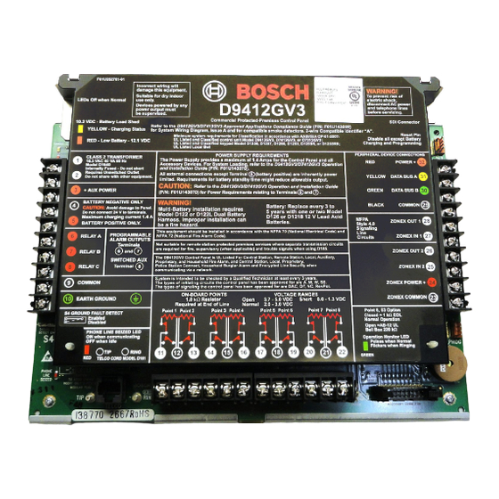
S3, Point 8 EOL selection Color-coded battery leads Operation monitor LED (green) Ground fault detect enable Accessory connector Phone LED (red) Programming connector Reset pin Telephone cord connector SDI quick connector F.01U.167.105 | 02 | 2010.11 UL Installation Instructions Bosch Security Systems, Inc. -
Page 9: Power Supply Side Wiring Diagrams
Control Panels Diagrams | en Power Supply Side Wiring Diagrams 2.2.1 D9412GV3/D7412GV3 Power Supply Side Wiring Diagram (D9412GV3 shown) Callout Description Callout Description If required by local AHJ, connect D113 Battery To Relay A or Relay B Lead Supervision Module. -
Page 10: D7212Gv3 Power Supply Side Wiring Diagram
(Batteries are not supervised.) Power limited, supervised RJ31X, primary telephone line Power limited To earth ground NOTICE! All external connections except Terminal 5 (battery positive) are power limited. F.01U.167.105 | 02 | 2010.11 UL Installation Instructions Bosch Security Systems, Inc. -
Page 11: Input Points And Peripheral Devices Wiring Diagram (D9412Gv3 Shown)
D130 Relay Module D125B Powered Loop Interface Module To UL Listed two-wire smoke detectors. Refer to Two-Wire Smoke Detectors in the D9412GV3/D7412GV3 Approved Applications Compliance Guide (P/N: F01U143069) for a listing of compatible two-wire smoke detectors. P105BL1 1 kΩ EOL resistor (P/N: F01U033966): For typical burglar alarm applications. -
Page 12: Sdi Devices Wiring Diagrams
| Diagrams Control Panels SDI Devices Wiring Diagrams 2.4.1 D9412GV3 SDI Devices Wiring Diagram Callout Description Callout Description D8125 POPEX No. 2 Up to 16 supervised keypads or fire annunciators Up to 8 D9210B Access Control Interface Modules Up to 119 D9127U/T POPITs... -
Page 13: D7412Gv3 Sdi Devices Wiring Diagram
NOTICE! All external connections except Terminal 5 (battery position) are power limited. Fire and Intrusion devices must be on separate circuits. Refer to ICP-SDI-9114 Installation Instructions (P/N: F01U030068). Bosch Security Systems, Inc. UL Installation Instructions F.01U.167.105 | 02 | 2010.11... -
Page 14: D7212Gv3 Sdi Devices Wiring Diagram
D8128D OctoPOPITs connected to the same terminal. Refer to the D8128D Installation Guide (P/N: F01U070537) or the D8129 Operation and Installation Guide (P/N: F01U036302) for specific information. NOTICE! All external connections except Terminal 5 (battery position) are power limited. F.01U.167.105 | 02 | 2010.11 UL Installation Instructions Bosch Security Systems, Inc. -
Page 15: Keyswitch Wiring
Ω Use 1 k EOL resistors if using one of the zones on the control panel or an OctoPOPIT. Use a 33 k resistor if using a POPIT. Bosch Security Systems, Inc. UL Installation Instructions F.01U.167.105 | 02 | 2010.11... -
Page 16: Power Supply And Power Outputs
3.1.1 Primary (AC) Power Circuit The primary source is a 16.5 VAC, 40 VA, internally-fused transformer (Bosch Security Systems, Inc. Model D1640). The control panel draws 200 mA when idle and 300 mA when in an alarm state. The total available auxiliary current is 1.4 A. Transient suppressors and spark gaps protect the circuit from power surges. -
Page 17: Power Terminals - Secondary
To increase battery back-up time, connect a second 12 V battery in parallel to the first battery. Use a D122 Dual Battery Harness to ensure proper and safe connection. Refer to the Standby Battery and Current Rating Chart in the D9412GV3/D7412GV3 Approved Applications Compliance Guide (P/N: F01U143069) or in the D7212GV3 Approved Applications Compliance Guide (P/N: F01U143080) for battery standby time calculations. - Page 18 Battery wires 6.4 mm (0.25 in.) minimum. To ensure proper spacing, use tie-wraps or similar devices to secure wires. Relay output wires Input or Zone wires Standby battery F.01U.167.105 | 02 | 2010.11 UL Installation Instructions Bosch Security Systems, Inc.
-
Page 19: Power Outputs - Circuit Protection
If the control panel is programmed for power supervision and a short circuit occurs on one of the power outputs, the control panel sends a BATTERY LOW or BATTERY MISSING for Bosch Security Systems Modem IIIa Communication Format, or a Battery Missing/Dead (311) or Low System Battery (302) for Contact ID Format. -
Page 20: Power Outputs - Continuous Power Output Terminals 3, 8, 24, And
Relays can be assigned to one or more areas. The Bosch defaults set Relay A (Terminal 6) as a Steady Alarm Bell output, Relay B (Terminal 7) as a Pulsed Fire Bell output, and Relay C (Terminal 8) as a Verification or Reset output for smoke detectors. -
Page 21: Fire System Power Formula
The default program sets Relay C (Terminal 8) as a verification and reset relay. Refer to Relay Parameters and Point Assignments in the D9412GV3/D7412GV3 Program Entry Guide (P/N: F01U170807) or in the D7212GV3 Program Entry Guide (P/N: F01U170808) for instructions on programming verification/reset relays and points. -
Page 22: Specifications
Connection: RJ31X or RJ38X jack can connect the control panels. Connections Two telco Bosch Security Systems, Inc. D928 Dual Phone Line Module required for two lines: phone line service. Supervision supplied by the control panel. F.01U.167.105 | 02 | 2010.11 UL Installation Instructions Bosch Security Systems, Inc. -
Page 23: Terminal Wiring Requirements
18 AWG min (up to 14 AWG max) + AUX POWER Terminal accommodates 14 to 22 AWG, use appropriate wire size based on current BATTERY - Bosch supplied wire lead, included with panel BATTERY + Bosch supplied wire lead, included with panel RELAY A... - Page 24 SDI POWER Terminal accommodates 14 to 22 AWG, use appropriate wire size based on peripheral device current *D9412GV3 only. Terminals 25 and 26 are NOT USED on D7412GV3 and D7212GV3 Control Panels. F.01U.167.105 | 02 | 2010.11 UL Installation Instructions...
-
Page 25: Compatible Accessories
Release Module D8132 Battery Charger Module D9127U/T POPIT Module D9131A Parallel Printer Interface Module D9210B Access Control Interface Module DX4020 Network Interface Module ITS-DX4020-G GPRS/GSM Communicator ICP-SDI-9114 SDI Splitter Bosch Security Systems, Inc. UL Installation Instructions F.01U.167.105 | 02 | 2010.11... -
Page 26: Circuit Classes
Onboard points, points 1 to 8, are Class B, Style B Initiating-Device Circuits. Zonex Bus or Buses Zonex buses are Class B, Style 4 Signaling Line Circuits. Notification Appliance Circuit (NAC) The control panels do not have an onboard NAC. F.01U.167.105 | 02 | 2010.11 UL Installation Instructions Bosch Security Systems, Inc. - Page 28 Bosch Security Systems, Inc. 130 Perinton Parkway Fairport, NY 14450 www.boschsecurity.com © Bosch Security Systems, Inc., 2010...
Need help?
Do you have a question about the D9412GV3 and is the answer not in the manual?
Questions and answers