Table of Contents
Advertisement
Advertisement
Table of Contents

Related Manuals for Vitus Audio RI-100


Summary of Contents for Vitus Audio RI-100
- Page 1 RI-100 Owner’s Manual...
- Page 2 RI-100 | Version 1...
- Page 3 (electronic, mechanical, photocopying, recording or otherwise) without the prior written permission of Vitus Audio. Any person who does any unauthorized act in relation to this publication may be liable to criminal prosecution and civil claims for damages.
- Page 4 RI-100 | Version 1...
-
Page 5: Table Of Contents
Connecting the RI-100 ..14 RI-100 Inside view ..50 RI-100 Front ... . 51 RI-100 | Version 1... -
Page 6: On A Personal Note
Certificate Model: RI-100 Product ID/Serial __________________________________ Product Build Date __________________________________ Signed __________________________________ All products details, specifications and measurements are recorded for your RI-100 and kept by Vitus Audio. RI-100 | Version 1... -
Page 7: From The Creator
Foreword At Vitus Audio everything Generally we’re after super works until proven not to. neutral, super detailed and First of all, thank you for This way we always try to super dynamic reproduction choosing the Vitus Audio push the limits and explore without “loosing”... -
Page 8: About This Manual
About this manual Introduction to the Reference Series This is your RI-100 owner’s The Vitus Audio Reference manual. The following pages Series is a true high-end series will describe, as clearly as of products, which is build on possible, how to get your RI- our true dedication to neutral 100 operating fast and simple. - Page 9 You might damage both your back and the amplifier if extra care is not applied. Vitus Audio A/S cannot be held responsible for any damage that is a consequence of uncareful handling of the unit.
-
Page 10: Getting Started
Now remove the side protective foam, this will make it easier Foam Sides to grab hold of the RI-100. 6 pieces Two people carefully lift the amplifier out of the box, and put it directly onto the floor. -
Page 11: Device Overview
1. getting started Device overview Front panel: Anodized Aluminium 435 mm Body: Powder coated Aluminium Total weight: 40 KG Figure 2 Device overview RI-100 | Version 1... -
Page 12: The Topology Of The Volume Control
The topology of the volume control. The topology of the volume To prevent pop in the output, control used in the RI-100 is we have chosen to first add very different compared to the the new shunt resistors, and “standard”. The RI-100 uses a... -
Page 13: Connecting
2. connecting Turning the RI-100 on and off. Always turn on the products beginning from the source: CD player a pre-amplifier a power amplifier. Always turn off your products in reverse order: Power amplifier a pre-amplifier a CD player. ... -
Page 14: Rear Panel
2. connecting RI-100 rear panel Connecting the RI-100 Place the RI-100 on its shelf. Outputs Connect all the sources to the inputs of the RI-100, (labelled Speaker left INPUT 1 to 5 on the rear Speaker out panel.) Speaker right... - Page 15 (-) speaker output connect (-) speaker output to ground. to ground. Preout Input 4 Input 5 / RIAA Preout Input 5 / RIAA Input 4 MAINS Optional DAC interface Optional Headamp interface RI-100 Rear panel. Figure 5 Fuse RI-100 | Version 1...
-
Page 16: Operation
3. operation Operation modes RI-100 Front panel. Figure 6 RI-100 | Version 1... -
Page 17: Normal Mode
In this mode you can alter the settings of the RI-100. 3. Standby mode. In this mode the controls of the RI-100 are deactivated. The RI-100 does not shut down in Standby Mode in order to maintain an optimal working temperature RI-100... -
Page 18: Functions - Left Front Panel
3. operation Functions – left front panel RI-100 Left front panel. Figure 7 Normal mode Menu mode In normal mode there are You enter menu mode, by 3 basic functions/buttons pushing the ”MENU” button available on the left front. once in Normal mode. In the... -
Page 19: Functions - Right Front Panel
3. operation Functions – right front panel RI-100 Right front panel. Figure 8 Normal mode Menu mode In normal mode there are In the text-menu it is possible 3 basic functions/buttons to change the name of the available on the right front: input. -
Page 20: The Menu Structure
This has a direct influence You can modify the settings The RI-100 comes with 5 on the typical volume level of the RI-100. You do this by inputs. The settings for that is needed for a specific entering the menu. On page... -
Page 21: Volume Settings
3. operation Remote settings Volume settings The RI-100 is standard shipped The RI-100 starts up in with a Apple Remote. the same volume step on initialization. You can select The Apple remote that in which volume step, the RI- comes with the RI-100 can 100 should initialize. - Page 22 Change the initial dB step of the Change the settings of input X. m e n u . volume in the RI-100 to any step USED between -99 and12.dB Select whether input X has to be OUTPUT VOL.STEP...
-
Page 23: The Menu Structure
INPUT 2 TEXT INPUT 3 OFFSET INPUT 4 -12 dB / +12 dB FIXED SET FIX FIX ON / FIX OFF INPUT 5 ADJUST -99 dB / +12 dB BACK Figure 9 The RI-100 Menu strukture RI-100 | Version 1... -
Page 24: Operation & Service
There are potentially contain no user serviceable dangerous voltages present parts except from the mains inside. Should your RI-100 fuse. Should your RI-100 show show signs of malfunction, signs of malfunction, please then please contact your contact your dealer or Vitus dealer or Vitus Audio. -
Page 25: Mains Fuse
For an explanation of how to In case of malfunction the replace the fuse see chapter 4 unit must be returned to Vitus “replacing a blown fuse”. Audio for repair. RI-100 | Version 1... -
Page 26: Replacing A Blown Fuse
Pull the fuse carrier out. There is a spare fuse Take the blown fuse out of available in the fuse carrier. the fuse carrier and throw it away. Figure 10 Replacing a blown fuse RI-100 | Version 1... - Page 27 4. operation & service Flip the spare fuse out using Place the spare fuse in the a pointy object.. fuse carrier and click the fuse in place. Push the fuse carrier back into the machine. RI-100 | Version 1...
-
Page 28: Warranty
Vitus this Limited Warranty shall be to be free of manufacturing Audio or an authorized repair to return the product to Vitus defects in material and center by the customer at his Audio or an authorized Vitus workmanship, subject to the or her sole expense. - Page 29 8. MISCELLANEOUS product must be accompanied Any implied warranties relating by a written description to the above product shall be of the defect on a VITUS limited to the duration of this AUDIO RETURNED GOODS warranty. The warranty does AUTHORIZATION form.
- Page 30 In the unlikely event of service required beyond the capabilities of the importer, Vitus Audio will fulfill the conditions of the warranty. Such products must be returned at the owner’s expense to the Vitus Audio...
-
Page 31: Specifications
6. specifications RI-100 Specifications Rated Output Power…….........2 x 300Wrms in 8 ohm Class AB Frequency Respon..............………..DC to +500KHz Signal to Noise Ratio……………………..……......………..……> 100dB THD+ Noise………………………....………………………..Better than 0,01% Input Sensitivity……....with volume set @ 0dB / RCA = 2, 6 / XLR 5,2V RMS Input Impedance……..…....………….………...RCA = 22KΩ... -
Page 32: Load Values Of The Riaa Module
125 Ω between 105 Ω and 47 kΩ. 150 Ω We recommend you to use the 160 Ω RIAA module in the RI-100 with 175 Ω cartridges that have an output value higher than 500µV rms. 190 Ω 240 Ω... -
Page 33: Examples Operation
R L - Setting the MENU SELECT MUTE STANDBY load impedance. The RI-100 is standard set RP-101 Left front panel. Figure 7. to a load impedance of 110 Ω MENU In the example we will change the settings of the RP-101 to... -
Page 34: Example 2
Enter the “MENU” submenu and scroll down using the button. The display now shows Output. Press the “SELECT” button. The display now shows HEADPHONES. Press “SELECT” the output of the RI-100 is now changed from SPEAKERS to HEADPHONES RI-100 | Version 1... -
Page 35: Example 3
NO. Press the button. The RESET NO display now shows RESET YES. RESET YES Press the SELECT button. The SELECT settings of the RI-100 have now RESET been restored. Figure 12 Example 2 Restoring settings RI-100 | Version 1... -
Page 36: Example 4
The display now shows NO PAIR. This means that the The remote is (fresh from the remote and the RI-100 are now box) not paired to the RI-100. unpaired. When you go into the menu to RI-100 Left front panel. - Page 37 7. examples operation Example 5 Pairing the remote Changing the Re- Follow these steps and the RI-100 mote ID. 1.Press and hold the standbybutton. Follow these steps When two devices have the same Remote ID. Then you can 2.Press and hold the 1.Press and hold the...
- Page 38 Figure 15 Example 5 Setting initial volume step Set the volume step to -30 using the and the buttons. Press SELECT and leave the menu. Next time you initialize the RI-100, the volume step will be -30. RI-100 | Version 1...
-
Page 39: Example 5
RI-100 to remember REMEMBER SELECT the current volume step. The VOL.STEP RI-100 will start up in this volume step when it leaves standby. Figure 16 Example 6 Remember volume step This volume step however is not Go to REMEMBER press remembered when the power SELECT. -
Page 40: Example 7
7. examples operation Example 8 Changing brightness from 0 to 1. You can adjust the brightness of the display. RI-100 Left front panel. Figure 7. Press the“MENU”button to enter Menu Mode. Navigate to the MENU “BRIGHTNESS” submenu, using the function buttons on... -
Page 41: Example 8
You can set the volume of an This is the volume step in which input to a fixed dB step. The V.INIT the RI-100 initialises as a standard. input is then locked to this dB BRIGHT Adjust the volume step to -30 dB step and can not be adjusted and press the SELECT button. -
Page 42: Example 10
SELECT BACK You can set different offset- DATA values for the different inputs. RESET You actually adjust the gain RI-100 Left front panel. Figure 7. of one individual input. This REMOTE will reduce the differences Press the“MENU”button to V.INIT in volume, when you switch enter Menu Mode. -
Page 43: Example 11
The amplifier now DATA not using. The system will skip automatically turn the volume RESET RI-100 Left front panel. Figure 7. the disabled inputs, up or down when you change REMOTE and jump to the next input. -
Page 44: Example 12
Changing the name of INPUT 1 to SCD-010. Press the“MENU”button to enter Menu Mode. Navigate to the TEXT MENU RI-100 Left front panel. Figure 7. submenu, using the function buttons on the left front LEAVE name of INPUT1 has now... -
Page 45: Example 13
” sub-menu in the previous If you want to use an input- example. name that is not in the RI-100 Right front panel. predefined list, then it is Figure 8. The display is showing LINE 1 possible to manually add a MENU name to the list. -
Page 46: Examples Connecting Devices
7. examples connecting devices Connecting devices Vitus Audio Products 3rd Party Products Reference Series On examples1 2 and 3 we show you how the RI-100 can RCD-100 be connected to other devices. Headphones In our examples we used the following devices... -
Page 47: Connecting Devices 1
7. examples connecting devices Connecting devices 1 Optional Modules. The RI-100 has 3 upgrade possibilities. RIAA module DAC interface Headamp interface Units Passive Speakers RI-100 Turntable Media Center Headphones Figure 24 Optional Modules RI-100 | Version 1... -
Page 48: Connecting Devices 2
7. examples connecting devices Connecting devices 2 Active Subwoofer. It is possible to connect an active subwoofer to the Pre-out. Units Passive Speakerss Active Subwoofer RI-100 Turntable RCD-100 Figure 25 Active Subwoofer RI-100 | Version 1... -
Page 49: Connecting Devices 3
RCD-100. The RCD-100 is used as a DAC. The RI-100 is powering the hi- and mid-tones. The RS-100 is connected to the PRE-OUT of the RI-100. The RS-100 is powering the bass Units Speakers (Hi-Mid) Speakers (Low) -
Page 50: Pictures
8. pictures RI-100 Inside view Picture 1 RI-100 Inside view RI-100 | Version 1... -
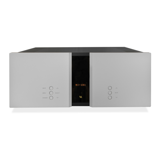
Page 51: Ri-100 Front
8. pictures RI-100 Front Picture 2 RI-100 Front RI-100 | Version 1... - Page 52 Handcrafted in Denmark AVA Group A/S (Vitus Audio), Sandgaardsvej 31, DK-7400 Herning, Denmark, Phone: +45 9626 8046, Fax: +45 9626 8045 e-mail: info@vitusaudio.com, web site: www.vitusaudio.com...
Need help?
Do you have a question about the RI-100 and is the answer not in the manual?
Questions and answers