Advertisement
Table of Contents
SERVICE MANUAL
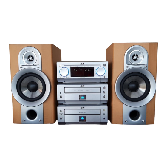
MICRO COMPONENT SYSTEM
REMOTE CONTROL RM-SUXG6E
PANEL
OPEN/CLOSE
DIMMER
ACTIVE
SLEEP
BASS EX.
CLOCK/TIMER
BASS
TREBLE
FM MODE
PLAY MODE
REPEAT
AUTO PRESET
TITTLE/EDIT
ENTER
PTY/EON
DISPLAY
/CHARA.
CANCEL
UP
<
>
SET
DOWN
MD
AUX
TAPE
CD
FM/AM
+
VOLUME
-
Unit composition
Contents
STEREO AMPLIFIER
CD / TUNER
CASSETTE DECK
SPEAKER SYSTEM
< ATTENTION >
When this model is repaired, a part of unit of "UX-G6/FS-G6" is necessary.
Contents
Safety precautions ----------------------------------- 1-2
Important for laser products ----------------------- 1-3
Preventing static electricity ------------------------- 1-4
Attention at repair reception ----------------------- 1-5
Instructions (UX-G6) --------------------------------- 1-6 - 15
AX-UXG6 ----------------------------------------------- 2-1
UX-G6/FS-G6
STANDBY/ON
M I C R O
C O M P O N E N T
S Y S T E M
U X - G 6 R
FM/AM
MULTI
JOG
VOLUME
MOS - FET
1 B I T
P • E • M
D • D • C O N V E R T E R
PHONES
COMPACT
DIGITAL AUDIO
DOLBY B NR
REC PAUSE
AUTO
REVERSE
REC
Model Name
AX-UXG6
XT-UXG6
TD-UXG6
SP-UXG6
COPYRIGHT
2000 VICTOR COMPANY OF JAPAN, LTD.
OPEN/CLOSE
AUX
(Please refer to page 1-5)
XT-UXG6 ----------------------------------------------- 2-11
TD-UXG6 ----------------------------------------------- 2-31
SP-UXG6 ----------------------------------------------- 2-46
Standard schematic diagrams -------------------- 2-47
Printed circuit boards -------------------------------- 2-56 - 60
Parts List ------------------------------------------------ 3-1 - 31
UX-G6/FS-G6
Area Suffix (UX-G6)
UB ............. Hong Kong
UP ..................... Korea
U ............... Other Areas
Area Suffix (FS-G6)
J ......... U.S.A./ Canada
We will separately issue the
parts list of J version.
No.20808
Feb. 2000
Advertisement
Table of Contents

Related Manuals for JVC UX-G6


Summary of Contents for JVC UX-G6
-
Page 1: Table Of Contents
CASSETTE DECK TD-UXG6 SPEAKER SYSTEM SP-UXG6 < ATTENTION > When this model is repaired, a part of unit of “UX-G6/FS-G6” is necessary. (Please refer to page 1-5) Contents Safety precautions ----------------------------------- 1-2 XT-UXG6 ----------------------------------------------- 2-11 Important for laser products ----------------------- 1-3... -
Page 2: Safety Precautions
UX-G6/FS-6G Safety Precautions 1. This design of this product contains special hardware and many circuits and components specially for safety purposes. For continued protection, no changes should be made to the original design unless authorized in writing by the manufacturer. -
Page 3: Important For Laser Products
UX-G6/FS-G6 Important for laser products 5.CAUTION : If safety switches malfunction, the laser is able 1.CLASS 1 LASER PRODUCT to function. 2.DANGER : Invisible laser radiation when open and inter 6.CAUTION : Use of controls, adjustments or performance of lock failed or defeated. Avoid direct exposure to beam. -
Page 4: Preventing Static Electricity
UX-G6/FS-G6 Preventing static electricity Electrostatic discharge (ESD), which occurs when static electricity stored in the body, fabric, etc. is discharged, can destroy the laser diode in the traverse unit (optical pickup). Take care to prevent this when performing repairs. 1.1. Grounding to prevent damage by static electricity Static electricity in the work area can destroy the optical pickup (laser diode) in devices such as DVD players. -
Page 5: Attention At Repair Reception
Attention at repair reception < ATTENTION > When this model is repaired, a part of unit of "UX-G6/FS-G6" is necessary. A necessary unit is described to rear panel. Please keep the unit from the customer together when you repair this model. -
Page 6: Ax-Uxg6
UX-G6/FS-G6 AX-UXG6... -
Page 7: Disassembly Method
UX-G6/FS-G6 Disassembly method (AX-UXG6) Removing the top cover (See Fig.1) 1. Remove the two screws A and the four screws B attaching the top cover. 2. Remove the top cover from behind in the direc- tion of the arrow while pulling the sides outward. - Page 8 UX-G6/FS-G6 Front sub panel assembly Removing the front sub panel assembly (See Fig.6 to 8) • Prior to performing the following procedure, remove the top cover and the front panel assem- CN704 bly. 1. Disconnect the card wire from connector CN704 on the back of the front sub panel assembly.
- Page 9 UX-G6/FS-G6 Regulator board Removing the regulator board (See Fig.10) • Prior to performing the following procedure, remove the top cover. 1. Disconnect the card wire from connector CN908 on the main board. CN906 Main board 2. Disconnect the harness from connector CN906 CN908 on the main board.
- Page 10 UX-G6/FS-G6 Removing the main board and the heat sink CN907 (See Fig.11 to 18) CN906 • Prior to performing the following procedure, remove CN908 the top cover and the rear cover. CN905 1. Disconnect the harness or card wire from connector...
- Page 11 UX-G6/FS-G6 Removing the slide gear motor assembly (See Fig.19 to 21) • Prior to performing the following procedure, remove the top cover and the regulator board . Slide gear motor assembly 1. Disconnect the harness from connector CN907 on the main board.
- Page 12 UX-G6/FS-G6 Front panel assembly <Front panel assembly> Removing the front board. (See Fig.22 to 24) • Prior to performing the following procedure, remove the top cover Multi-jog dial Volume dial and the front panel assembly. Fig. 22 1. Remove the seven screws R attaching the front...
-
Page 13: Description Of Major Ics
UX-G6/FS-G6 Description of major ICs LB1641 (IC901) : DC Motor driver 1. Pin Layout GND OUT1 P1 IN2 VCC1 VCC2 P2 OUT2 2. Pin Functions Input Output Mode OUT1 OUT2 Brake CLOCKWISE COUNTER-CLOCKWISE Brake... - Page 14 UX-G6/FS-G6 UPD780023 (IC701) : System control 1.Pin layout 2.Key matrix 64 ~ 49 KEYO1 KEYO2 KEYO3 KEYI1 CLOCK/TIMER TITLE/EDIT KEYI2 DISPLAY/CHARA. KEYI3 PLAYMODE CANCEL ENTER 17 ~ 32 KEYI4 RECMODE 3.Pin function Pin No. Symbol Function JOG1A,B Rotary encoder input from JOG1(JS701)
- Page 15 UX-G6/FS-G6 Block diagram (AX-UXG6) CN908 CN704 2-10...
-
Page 16: Xt-Uxg6
UX-G6/FS-G6 XT-UXG6 2-11... - Page 17 UX-G6/FS-G6 Disassembly method Top cover (XT-UXG6) Removing the top cover (See Fig.1) 1. Remove the two screws A and the four screws B attaching the top cover. Remove the top cover in the direction of the arrow while pulling it.
- Page 18 UX-G6/FS-G6 Removing the front panel assembly Rear panel (See Fig.5 and 6) • Prior to performing the following procedure, remove the top cover. 1. Remove the seven screws E attaching the rear joint c joint c panel on the back of the body and release the two joints "c"...
- Page 19 UX-G6/FS-G6 CN451 Removing the analog in/digital out board and the relay board (See Fig.8 to 10) • Prior to performing the following procedure, remove the top cover, the rear panel and the system control board. 1. Cut the tie band fixing the harness on the side of the body.
- Page 20 UX-G6/FS-G6 Removing the CD mechanism assembly main & CD servo board (See Fig.12 to 14) • Prior to performing the following procedure, remove the top cover, the front panel assembly, the rear panel, the system control board and the analog in/digital out board.
- Page 21 UX-G6/FS-G6 << CD Mechanism section >> Removing the traverse mechanism CD tray 1. Remove the tray stopper screw "A" on the CD tray 2. The CD tray is drawn out in the direction of the arrow. Tray stopper screw A...
- Page 22 UX-G6/FS-G6 Removing the spindle motor 1. Remove the traverse mechanism 2. The turntable is removed from the spindle motor, and remove two screws D which is the fixation of the spindle motor. 3. Remove the screw which is the fixation of the...
-
Page 23: Flow Of Functional Operation Until Toc Read
UX-G6/FS-G6 Flow of functional operation until TOC read Check Point Slider turns REST Play Key Power ON Confirm that the voltage at the pin5 SW ON. of CN440 is "H"\"L"\"H". Automatic tuning of TE offset Check that the voltage at the... - Page 24 UX-G6/FS-G6 Maintenance of laser pickup Replacement of laser pickup (1) Cleaning the pick up lens Before you replace the pick up, please try to Turn off the power switch and,disconnect the clean the lens with a alcohol soaked cotton power cord from the ac outlet.
- Page 25 UX-G6/FS-G6 Description of major ICs AN8806S (IC462) : RF & Servo AMP 1.Pin layout PDAC PDBD LDON PDER PDFR TBAL RF OUT FBAL RF IN C.AGC EF OUT C.ENV TE OUT C.EA CROSS CS BDO TE BPF VDET CS BRT...
- Page 26 UX-G6/FS-G6 3. Pin function Pin No. Symbol Description APC amp input terminal APC amp output terminal LD ON APC ON/OFF control terminal Connect to ground Power supply Inverse input pin for RF amp RFamp output RF OUT RF IN RF input Connecting pin of AGC loop filter C.AGC...
- Page 27 UX-G6/FS-G6 BA6897FP (IC463) : 4channel driver TC9164AN (IC432) : Analog switch 1.Function D.BUF Switch to On/Off of S1 to S8 by control of LSI. CH1-OUTA D.BUF 2.Terminal Lay out & Block Diagram CH1-OUTB CH4-OUTA TC9164AN D.BUF CH1-INA Level CH4-OUTB Level...
- Page 28 UX-G6/FS-G6 MN35511AL (IC461) : Digital servo & Processor 1.Pin layout 2.Block diagram VCOF2 AVDD2 DEMP/TEST2 OUT2D 8tims OUT2C Over VCO2 Sampling Method LRCKI BCKI OUT1D Digital SDATAI Filter OUT1C IOSEL AVSS2 BLKCK CLDCK FLAG SBCK SBCK2 IP FLAG SUBC DEMPO...
- Page 29 UX-G6/FS-G6 3. Pin function symbol I/O symbol I/O Description Description Bit clock output for SRDATA Non connect BCLK TOFS LRCK Identification signal output of Lch and Rch PLAY Non connect SRDATA WVEL Non connect Serial data output DVDD1 Power supply (Digital)
- Page 30 UX-G6/FS-G6 LC72136N (IC2) : PLL frequency synthesizer 1. Pin layout FM/AM LPFOUT LPFIN CLOCK FM/ST/VCO FMIN AM/FM AMIN IFCONT SDIN IFIN 2. Block diagram Phase Reference Detector Driver Charge Pump Swallow Counter Swallow Counter 1/16,1/17 4bit 1/16,1/17 4bit Unlock Detector...
- Page 31 UX-G6/FS-G6 TA2057N (IC1) : FM/AMP IF AMP & Detector 1.Block Diagrams IF IN Vstb IF IN QUAD FM OUT AM OUT MPX IN LPF 1 LPF 2 L OUT DIVIDE MUTE DECODE LEVEL AM/FM MONO BUFF IF REQ BUFF IF OUT...
- Page 32 UX-G6/FS-G6 TA7439 (IC435) : Rear/center volume 1.Pin layout CREF DIG GND TREBLE(R) AGND TREBLE(L) ROUT MIN(L) LOUT MOUT(L) R-IN4 BOUT(L) R-IN3 BIN(L) R-IN2 BOUT(R) R-IN1 BIN(R) L-IN1 MOUT(R) L-IN2 MIN(R) L-IN3 L-IN4 MUXOUTR MUXOUTL TDA7439 2.Block diagram L-IN1 SPEAKER MIDLE...
- Page 33 UX-G6/FS-G6 UPD784214AFG501 (IC501) : Sysem controller 1.Pin layout 80 ~ 51 1 ~ 30 2. Pin function Symbol Description Symbol Description PERIODO Tuner PLL control output AVSS Connect to GND Stereo indicator signal input CD/OPT Digital input selector TCLOCK Tuner PLL control output...
- Page 34 UX-G6/FS-G6 Block diagram (XT-UXG6) CN457 CN435 CN433 CN432 CN431 CN451 CN453 CN454 CN503 CN504 CN439 CN440 CN506 CN505 2-29...
- Page 35 UX-G6/FS-G6 << M E M O >> 2-30...
-
Page 36: Td-Uxg6
UX-G6/FS-G6 TD-UXG6 2-31... - Page 37 UX-G6/FS-G6 Disassembly method Top cover (TD-UXG6) Removing the top cover (See Fig.1) 1. Remove the two screws A and the four screws B attaching the top cover. 2. Remove the top cover from behind in the direc- tion of the arrow while pulling the sides outward.
- Page 38 UX-G6/FS-G6 Rear panel Removing the rear panel (See Fig.6 and 7) • Prior to performing the following procedure, remove the top cover. 1. Remove the three screws E attaching the rear Joint c Joint c panel on the back of the body and release the two joints "c"...
- Page 39 UX-G6/FS-G6 Connector on the Removing the loading mechanism board/ motor board Dolby board (See Fig.9) • Prior to performing the following procedure, remove the top cover and the rear panel. CN632 1. Disconnect the harness from the connector on the motor board in the cassette mechanism.
- Page 40 UX-G6/FS-G6 <<Cassette Mechanism Section>> Detaching the cassette loading mechanism (Fig. 1 to 3) Loading gear 1. Turn the loading drive gear in the direction shown by the arrow so that the head relay board can be re- moved. 2. Remove the screw A securing the head relay board (to protect the head wire).
- Page 41 UX-G6/FS-G6 Detaching the capstan motor (Fig. 4) 1. Disconnect the capstan motor wiring. 2. Remove the two screws F securing the capstan motor. Fig. 4 Detaching the mechanism (Fig. 5 to 11) 1. Head block Remove the two screws G securing the head block (when installing, attach to the return gear arm).
- Page 42 UX-G6/FS-G6 4. Leaf switch replacement Unsolder Remove the two screws H securing the leaf switch board. Fig. 8 5. Mechanism base (1) Pull out the reel disk. Guide (2) Detach the brake arm. Pull up the brake arm by releasing the stopper Reel idle gear on the brake arm shaft.
- Page 43 UX-G6/FS-G6 Assembling (Figs. 11 to 13) 1. Set the cam gear in the position shown in the figure. 2. Set the spring as shown in the figure. 3. Set the solenoid plunger (shaft). 4. Attach to the mechanism base. 5. Slide the head return slider (white plastic) in the direction shown by the arrow to position the stud.
- Page 44 UX-G6/FS-G6 Main adjustment 1.Measuring instruments required for adjustment (1) Low frequency oscillator (6) 600 resistors and so forth (for attenuator This oscillator should be capable of outputting matching) 0dB (0.775V) at the 600W terminal at an (7) Distortion meter (band pass filter) oscillation frequency of 50 - 20kHz.
- Page 45 UX-G6/FS-G6 Procedures for adjusting the mechanism section Caution for Changing the Head Remove the screw provided from right above the head. At this time, peel the screw locks around the head by using a sharp-pointed device. Moreover, use the screw driver matching the corresponding screw.
- Page 46 UX-G6/FS-G6 Procedures for adjusting the electrical circuit The following adjustments should be performed after adjusting the tape traveling and head angles. • The sequence of adjustment should in principle be according to the following order of description. • The adjustment items denoted by asterisk should be performed whenever the head has been changed.
- Page 47 UX-G6/FS-G6 Adjusting Items Adjusting position Remarks Reference value position Adjustment of 1.While applying 1kHz -28.8dB L:VR614 Normam tape: The left and right level recording and to the line input terminal, R:VR624 -25.5dBs difference of both normal playing confirm that the sensitivity 0.5dB...
- Page 48 UX-G6/FS-G6 Description of major ICs BA8221AN (IC634) : ALC 510K 510K MUTE MUTE HA12136A (IC635) : Noise reduction amplifire BIAS REC/PB SIDE BUFFER CHAIN BIAS BUFFER SIDE CHAIN Vref ON/OFF 2-43...
- Page 49 UX-G6/FS-G6 MN171601AJABF (IC671) : System control 1.Pin layout 2.Key matrix 32 ~ 17 KEYO0 KEYO1 KEYI0 REC PAUSE STOP < > KEYI1 REVERSE KEYI2 DOLBY B NR OPEN/CLOSE 49 ~ 64 3.Pin function Pin No. Symbol Function Switching to R/P head...
- Page 50 UX-G6/FS-G6 Block diagram (TD-UXG6) CN636 CN646 CN667 CN637 CN635 CN647 CN634 CN644 CN648 2-45...
-
Page 51: Sp-Uxg6
UX-G6/FS-G6 Disassembly method (SP-UXG6) Removing the ornament panel assembly 1. Remove the saran board from the speaker box. (Saran board can be detached by pulling the side of saran board forward.) (See Fig.1) Joint part 2. A minus driver is inserted in the space between the ornament panel and the cabinet in the bottom part of the main body little by little.
Need help?
Do you have a question about the UX-G6 and is the answer not in the manual?
Questions and answers