Table of Contents
Advertisement
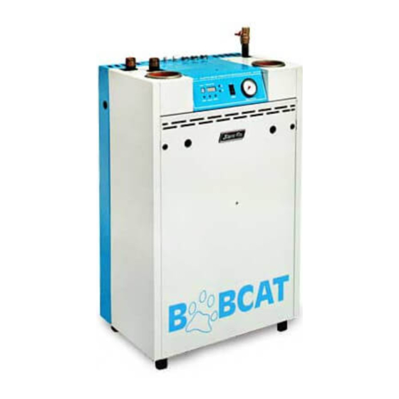
BOBCAT
DIRECT-VENT SEALED COMBUSTION CONDENSING BOILER
HOT WATER MODELS B-120A and B-200A
GAS-FIRED BOILERS FOR NATURAL AND L.P . PROPANE GASES
INSTALLATION AND OPERATING INSTRUCTIONS
TABLE OF CONTENTS
Dimensions, Rating and Orifice Sizes...........................................2
Identification of Parts .....................................................................3
Installation Requirements..............................................................4
Contamination Prevention.............................................................5
Mounting the boiler on a wall ........................................................6
Venting Application........................................................................6
Boiler Room Air Supply and Ventilation ........................................6
Non-Direct Vent Installation...........................................................6
Flue Gas Venting Requirements ...................................................7
Additional Installation Requirements for Massachusetts..............7
Vent and Air Intake Material...........................................................7
PVC/CPVC Pipe General Assembly Method ................................8
Vent and Air Intake Restrictions ....................................................8
Sidewall Venting, Non-Direct Vent ................................................9
Vent Termination Location and Clearance ....................................9
Non-Direct Vent Vertical Venting ...................................................9
Direct Vent Installation...................................................................9
Sidewall Venting, Direct Vent ........................................................9
Vent/Air Intake Termination Installation .......................................16
Direct Vent, Venting and Air Intake through a Roof ....................17
Venting and Air Intake Regular Inspection..................................18
Condensate Removal System.....................................................18
Gas Piping ...................................................................................18
Electrical Wiring...........................................................................19
Wiring Diagram............................................................................20
Single and Multi Zoning ..............................................................22
Water Piping ................................................................................24
Operating Instructions.................................................................30
Boiler Control Display..................................................................30
Boiler Control...............................................................................30
Sequence of Operation ...............................................................36
Gas Input Rate Adjustment .........................................................37
Safety Check ..............................................................................38
Care and Maintenance ................................................................41
General Troubleshooting Guide..................................................42
Appendix A&B ............................................................................43
The venting system of this boiler is under positive pressure. Leakage
from this system can be hazardous and if not avoided can result in
death or serious injury. In addition to the recommendations within this
manual and the User's Information Manual, the venting system, from
the flue collector to the outdoor discharge, must be carefully checked
annually by a qualified service agency.
Heating Contractor
Address
Phone Number
Printed in Canada 0711
WARNING
This manual must be left with owner and should be
hung on or adjacent to the boiler for reference.
IMPORTANT
READ ALL OF THE FOLLOWING WARNINGS AND
STATEMENTS BEFORE READING THE
INSTALLATION INSTRUCTIONS
WARNING
LIQUEFIED PETROLEUM (L.P .)
PROPANE GAS-FIRED BOILERS
Installation location ONLY as permitted in paragraph
entitled "LIQUEFIED PETROLEUM (L.P .) PROPANE GAS-
FIRED BOILER LOCATION" on page 5 of this instruction
book.
The above warning does not apply to NATURAL
gas fired boilers.
The installation must conform to the requirements of the
authority having jurisdiction or, in the absence of such
requirements, to the National Fuel Gas Code, ANSI Z223.1-
latest edition or
CSA B149.1-05 for natural gas and
propane
. The installation must also conform to the
additional requirements in this Slant/Fin Instruction Book.
In addition, where required by the authority having juris dic -
tion, the installation must conform to American Society of
Mechanical Engineers Safety Code for Controls and Safety
Devices for Automatically Fired Boilers, No. CSD-1 or
B149.1-05 for natural gas and propane
conflict in the above requirements, then the more stringent
requirement will apply.
WARNING
This boiler, gas piping and accessories must be
installed, connected, serviced and repaired by a
trained, experienced service technician, familiar with all
precautions required for gas-fired equipment and
licensed or otherwise qualified, in compliance with the
authority having jurisdiction.
Boiler Model Number
Boiler Serial Number
Installation Date
Part No. 86-5736 Publication No. B -40 Rev. G
CSA
. If there is any
Advertisement
Table of Contents

Related Manuals for Slant/Fin B-120A


Summary of Contents for Slant/Fin B-120A
-
Page 1: Table Of Contents
This manual must be left with owner and should be hung on or adjacent to the boiler for reference. DIRECT-VENT SEALED COMBUSTION CONDENSING BOILER HOT WATER MODELS B-120A and B-200A GAS-FIRED BOILERS FOR NATURAL AND L.P . PROPANE GASES INSTALLATION AND OPERATING INSTRUCTIONS... -
Page 2: Dimensions, Rating And Orifice Sizes
Bobcat Models B-120A and B-200A RATINGS AND DIMENSIONS 108mm 178mm (7") (4-1/4") 58mm (2-1/4") 102mm (4") 114mm (4-1/2") 45mm 356mm (1-3/4") (14") Figure 1. Dimensions data B-120A mB-200Am Dimension 23.875 31.875 1016 WARNING: Bobcat Boiler 1) Primary/Secondary pumping must be used, see pages 26/27/28. -
Page 3: Identification Of Parts
Bobcat Models B-120A and B-200A LOCATION AND IDENTIFICATION OF PARTS Figure 2. Location and identification of parts (model B-120A is shown) -
Page 4: Installation Requirements
Bobcat Models B-120A and B-200A MINIMUM CLEARANCES FROM COMBUSTIBLE INSTALLATION REQUIREMENTS CONSTRUCTIONS The installation must conform to the requirements of the authority having jurisdiction or, in the absence of such A. Minimum clearances to the exterior surfaces of the boiler requirements, to the National Fuel Gas Code, ANSI Z223.1-... -
Page 5: Contamination Prevention
Bobcat Models B-120A and B-200A CONTAMINATION PREVENTION The combustion air supply must not be susceptible to contami- nation sources, whether the combustion air comes from the interior or exterior of the building. Contaminated air can cause corrosion or other damage to the heat exchanger and compo- nents of the boiler, causing failure of these parts or unsafe operation. -
Page 6: Mounting The Boiler On A Wall
The Bobcat B-120A and B-200A boilers must be vented by 3" will be secure, devoid of seams or cracks. diameter Certified PVC or CPVC Venting to ULC S636, or the Place the bracket in the selected location, with the 2 tabs proper 3”... -
Page 7: Flue Gas Venting Requirements
FLUE GAS VENTING REQUIREMENTS The Bobcat B-120A and B-200A series boilers are high efficiency, mechanically forced draft boilers and, therefore, require different venting arrangements than natural draft, lower efficiency boilers. -
Page 8: Pvc/Cpvc Pipe General Assembly Method
Discard any rags used to avoid later getting the intake only) cement on hands, clothes and equipment. 6. The B-120A and B-200A boilers are equipped with a built- VENT AND AIR INTAKE RESTRICTIONS in condensation drain and trap. The trap must be filled 1. -
Page 9: Sidewall Venting, Non-Direct Vent
Figures 11 and 12 show typical sidewall direct venting, using A. SIDEWALL VENTING - NON-DIRECT VENT a Slant/Fin vent/air intake termination. There are 2 different models of vent/air intake termination available. One is Figures 7 and 8 show typical horizontal sidewall venting. For... - Page 10 Bobcat Models B-120A and B-200A BOBCAT MODELS B-120A and B-200A NON-DIRECT VENT, SIDEWALL VENTING 3” 3” All joints must be liquid and pressure tight. Use dia. Certified PVC or CPVC Venting or U/L listed single wall dia. AL29-4C S.S.*. venting materials (See page 7).
- Page 11 3" DIA. CERTIFIED PVC OR CPVC VENTING VENT PIPE OR STAINLESS STEEL VENTING MATERIAL FOR VENT Figure 9. Bobcat models B-120A and B-200A - non-direct vent, venting through the roof * AL 29-4C IS A REGISTERED TRADEMARK OF ALLEGHENY LUDLUM CORP.
- Page 12 3" DIA. CERTIFIED PVC OR CPVC VENTING PIPE OR STAINLESS STEEL VENTING MATERIAL FOR VENT Figure 10. Bobcat models B-120A and B-200A - non-direct vent, utilizing an existing chimney as a chase. * AL 29-4C IS A REGISTERED TRADEMARK OF ALLEGHENY LUDLUM CORP.
- Page 13 Bobcat Models B-120A and B-200A BOBCAT MODELS B-120A and B-200A - DIRECT VENT, SIDEWALL VENTING All joints must be liquid and pressure tight. Use 3” dia. Certified PVC or CPVC Venting or U/L listed single wall 3” dia. AL29-4C S.S.*. venting materials (See page 7).
-
Page 14: Alternate Sidewall Venting For Direct Or Non-Direct Venting
30.48 m 3. In cold climates, install an insolated enclosure around the (100 ft.) for B-120A and 15.24 m (50 ft.) for B-200A. piping to protect from freezing. 305 MM (12") MIN. - Page 15 Bobcat Models B-120A and B-200A 3" DIA. PVC/CPVC PIPE FOR AIR INTAKE INSIDE TERMINATION PLATE 3" DIA. CERTIFIED PVC OR CPVC VENTING PIPE FOR VENT SCREW OUTSIDE TERMINATION PLATE 3” DIA. CERTIFIED PVC OR CPVC VENTING COUPLING WITH SCREEN 3" DIA. CERTIFIED PVC OR CPVC...
-
Page 16: Vent/Air Intake Termination Installation
Bobcat Models B-120A and B-200A VENT/AIR INTAKE TERMINATION FOR PVC/CPVC VENT/AIR INTAKE TERMINATION FOR STAINLESS VENTING INSTALLATION STEEL VENTING INSTALLATION This termination is designed specifically for Heat-Fab Saf-T PVC and CPVC is acceptable for Air Intake, but for vent 3” diameter stainless steel venting system to be used as Venting Certified PVC or CPVC Venting must be the vent, and 3”... -
Page 17: Direct Vent, Venting And Air Intake Through A Roof
180° elbow facing down. The air intake opening must be at least 305mm (1 foot) below the vent opening. BOBCAT MODELS B-120A and B-200A - DIRECT VENT, VENTING AND AIR INTAKE THROUGH A ROOF All joints must be liquid and pressure tight. Use 3” dia. Certified PVC or CPVC Venting or U/L listed single wall 3" dia. -
Page 18: Venting And Air Intake Regular Inspection
A manual gas supply shut-off valve is provided on the boiler’s gas supply pipe. (See Figure 2, The Bobcat B-120A and B-200A boilers are equipped with a on page 3). Local codes may specify a manual main gas built-in condensation drain and trap. -
Page 19: Electrical Wiring
Bobcat Models B-120A and B-200A At 9.1m (30 ft.) length of pipe, match required Provide disconnect means and overload protection as capacity from table on this page (choose higher required. See boiler wiring diagram (Figure 16a) boiler capacity, in this case is 4.3m /hr. -
Page 20: Wiring Diagram
Bobcat Models B-120A and B-200A Figure 16a. Schematic wiring diagram. - Page 21 Bobcat Models B-120A and B-200A Figure 16b. Boiler Control. Figure 16c. Ladder wiring diagram.
-
Page 22: Single And Multi Zoning
Bobcat Models B-120A and B-200A Figure 17a. Multizoning of Bobcat boiler; zone valve system. Figure 17b. Multizoning of Bobcat boiler; pump zoning system using R845A relay. - Page 23 Bobcat Models B-120A and B-200A Figure 17c. Multizoning of Bobcat boiler; pump zoning system using R882A/B relays. Figure 17d. Single zoning of Bobcat boiler; pump Figure 17e. Single zoning of Bobcat boiler; pump zoning system zoning system using R845A relay.
-
Page 24: Water Piping
Bobcat Models B-120A and B-200A WATER PIPING 7. Water Treatment and Freeze Protection: A good water treatment program will not only extend the 1. Connection of system to boiler: useful life of this boiler but it will also save much of the... - Page 25 Bobcat Models B-120A and B-200A 25mm × 25mm × 19mm (1" × 1" × 3/4") NPT TEE Figure 18. Relief Valve and Low Water Cutoff Installation...
- Page 26 22 (40) 0.90 (3.0) 0.46 (1.5) 2.59 (8.5) 4.42 (14.5) 7.16 (23.5) Table 2a. Recommended pump models for domestic hot water tank piping to the Bobcat model B-120A boiler. Boiler Domestic Available Head Capability Left for Various Model Temp Flow...
- Page 27 Bobcat Models B-120A and B-200A EXPANSION TANK (DIAPHRAGM TYPE) Figure 20. Zoning with circulators.
- Page 28 Bobcat Models B-120A and B-200A DIRECT RETURN EXPANSION TANK (DIAPHRAGM TYPE) Figure 21. Zoning with zone valves.
- Page 29 Bobcat Models B-120A and B-200A DIRECT RETURN EXPANSION TANK (DIAPHRAGM TYPE) Figure 22. Piping a heating-cooling system to the boiler and a chiller.
-
Page 30: Operating Instructions
Bobcat Models B-120A and B-200A OPERATING INSTRUCTIONS 2. While “d” is blinking, boiler supply water temperature for DHW may be set to desired temperature. The setting range is between 104° to FILLING AND VENTING WATER SYSTEMS 185°F. A. Fill the system with water. Vent or purge of air. - Page 31 Bobcat Models B-120A and B-200A Figure 23. Display Board Table 3 BOBCAT BOILER DISPLAY BOARD “Boiler Operation Status” MODE DESCRIPTION & TEMPERATURE DISPLAY DISPLAY Boiler is in stand-by mode. Temperature display shows supply water Temp. Space heating mode. Temperature display shows supply water Temp.
- Page 32 Bobcat Models B-120A and B-200A Table 4 VIEWING AND CHANGING TEMPERATURES Temperature Display is in Farenheit only Press “SELECT” button for viewing different modes on “MODE DISPLAY” MODE DESCRIPTION & TEMPERATURE DISPLAY DISPLAY Space heating supply water temperature could be changed by pressing “Up/Down”...
- Page 33 Changing priority limited time. Settable from 20 to 80 minutes. The default value is 30 minutes. Boiler model selection, value is 0 for model B-120A and 4 for model B-200A Boiler model confirmation, value is 0 for model B-120A and 4 for model B-200A Weather compensation supply water reference temperature (space heating mode 1 or 2).
- Page 34 Bobcat Models B-120A and B-200A 200°F (93.3°C) Maximum 190°F water target (87.8°C) temp. 185°F (85°C) 180°F (82.2°C) 170°F (76.7°C) 160°F (71.1°C) 150°F (65.6°C) Water Supply Target Temp. [°F (°C)] 140°F (60°C) 130°F (54.4°C) 120°F (48.9°C) 110°F (43.3°C) 100°F (37.8°C) Minimum water 90°F...
- Page 35 Bobcat Force or attempted repair may result in a fire or explosion. B-120A and B-200A boilers under the ANSI Z21.13 - latest edition and CSA-B149-1-05 for natural gas and propane. D. DO NOT use this appliance if any part has been under water.
-
Page 36: Sequence Of Operation
Bobcat Models B-120A and B-200A BOBCAT BOILER MODELS B-120A and B-200A SEQUENCE OF OPERATION THERMOSTAT CALLS FOR HEAT CIRCULATOR(S) ON COMBUSTION BLOWER ON (AT MEDIUM SPEED) CONTROL LOCKOUT BLOWER SPEED CONFIRMED? DISPLAY SHOWS ERROR “A 33” 5 SECOND PRE-PURGE PERIOD... -
Page 37: Gas Input Rate Adjustment
Bobcat Models B-120A and B-200A IV. CHECK COMBUSTION AND FUEL INPUT RATE C. In the “System Test” mode in the “View and Changing System Setting” menu, use the “down” push button to A. Remove the boiler jacket front panel, by turning the 2 switch to the low firing rate. -
Page 38: Safety Check
Bobcat Models B-120A and B-200A If the fuel input is not at the rate specified on page 2 B. Thermostat Test: at the minimum firing rate, then the blower speed Set thermostat setting to low enough to end call for heat. - Page 39 Bobcat Models B-120A and B-200A Indicated by an “E” in the mode display. Operation is automatically restored, once the B. BLOCKING ERRORS: condition returns to normal or is fixed. The temperature display shows the error code. Pressing the “Reset” button is not required.
- Page 40 Bobcat Models B-120A and B-200A continued from page 39 ERROR CODE INDICATION REMEDY Check flue gas temperature, at the maximum firing rate and high water temperature. If the flue gas tem- perature reaches 100°C (212°F), check the fuel input Excess Flue Temperature rate and combustion.
-
Page 41: Care And Maintenance
A. Heat Exchanger: In the unlikely event of flue passage or I. GENERAL MAINTENANCE water passage blockage, service to remedy situation must be performed only by an authorized Slant/FIn representative. A. Safety check, see page 37. B. Burner: In the unlikely event of blockage or deterioration, B. -
Page 42: General Troubleshooting Guide
Bobcat Models B-120A and B-200A GENERAL TROUBLESHOOTING GUIDE FOR SERVICE PERSONNEL Only a trained, experienced service technician should perform troubleshooting. WARNING: Turn off all electrical power to the boiler before servicing. BURNER FAILS TO OPERATE - NO HEAT CAUSE REMEDY 1. - Page 43 Bobcat Models B-120A and B-200A APPENDIX A Thermostat Heat Anticipator Settings Fixed anticipator thermostats are not adjustable. The lower the anticipator setting (toward .18) the faster the thermostat will respond to a change in room temperature. Adjustable anticipator thermostats, depending on thermostat Too low a setting and the boiler will short cycle.
- Page 44 SLANT/FIN LTD/LTEE, 6450 Northam Drive, Mississauga, Ontario L4V 1H9 • Phone: (905) 677-8400 / FAX: (905) 677-1829 / Order Desk Fax: (905) 677-9015 www.slantfin.ca / E-mail: orderdesk@slantfin.ca / info@slantfin.ca ©Slant/Fin Corp. 2010...
Need help?
Do you have a question about the B-120A and is the answer not in the manual?
Questions and answers