Table of Contents
Advertisement
Quick Links
Download this manual
See also:
User Manual
Advertisement
Table of Contents
Troubleshooting

Related Manuals for GE CyberDome II


Summary of Contents for GE CyberDome II
- Page 1 CyberDome II Installation Manual...
- Page 2 GE Security and you. Read the following terms and conditions carefully before installing or using this software. This agreement provides a license from GE Security to use the software. It also contains warranty information, disclaimers, and liability limitations. Installing and/or using the software confirms your agreement to be bound by these terms and conditions.
- Page 3 Software to a human-perceivable form, nor create derivative works or programs based on the Software. 4. Limited warranty. GE Security warrants that for one (1) year from the date of delivery of the Licensed Product (Software Warranty Period), the functions contained in the Software will...
- Page 4 You further agree that this agreement is the complete and exclusive statement of the agreement between you and GE Security, and supersedes any proposal or prior agreement, oral or written, and any other communication relating to the subject matter of this agreement.
-
Page 5: Table Of Contents
Contents Preface ..................vii Conventions used in this document . - Page 6 CyberDome II Installation Manual Chapter 5. Troubleshooting, maintenance, support ....... . . 33 Troubleshooting .
-
Page 7: Preface
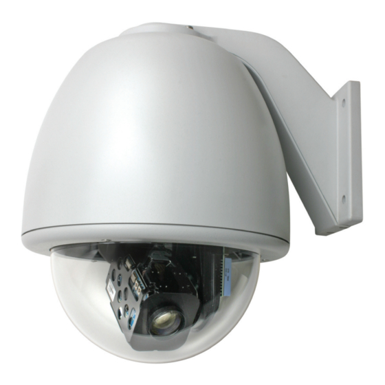
Preface This is the GE CyberDome II Installation Manual. This document includes an overview of the product and detailed instructions explaining: • how to install the housing; and • how to attach the camera. There is also information describing how to contact technical support if you have questions or concerns. - Page 8 CyberDome II Installation Manual...
-
Page 9: Introduction
Chapter 1 Introduction This chapter provides an overview of your CyberDome II dome system, including product contents and system requirements. In this chapter: Installation overview......... 2 Product description. -
Page 10: Installation Overview
Package containing two connectors (one two-pin for power and one six-pin for UTP video and data), and a small screwdriver. Note: The select version of CyberDome II will only have a 2-pin connector for primary RS-485 data. There is no UTP video or auxiliary RS-485 data. •... -
Page 11: System Requirements
If you need to return the unit, you must ship it in the original box. System requirements For proper operation, adhere to the following operational, load, cable, and power requirements for CyberDome II domes. - Page 12 CyberDome II Installation Manual Figure 2. Typical advanced system Digital recorder Video loop- through Matrix switcher Dome Mon 1 Mon 2 Mon 3 Mon 4 Data distributor Video RS-485 data EARTH GROUND EARTH GROUND RS485 RS485 RS422 IN RS422 IN...
-
Page 13: Minimum Load Requirements
Chapter 1 Introduction Minimum load requirements Table 1 lists the load requirements for all CyberDome II dome configurations. CAUTION: For safety, the mounting surface, hardware, and procedure used for securing the dome must support the weight of the dome, mount (if used), cables, and any structural or environmental vibration according to local codes. -
Page 14: Cable Management
Manufacturer, shielding, and rating affect the actual diameter of cables of the same gauge. GE leaves the selection of the appropriate cable to the discretion of the installer who is working with the local codes of the installation site. -
Page 15: Power Requirements
Chapter 1 Introduction Power requirements All CyberDome II domes require a 24 VAC power supply to operate the domes’ PTZ, camera, and heater/ blower, if present. The startup and running power requirements vary depending on the model (Table 3). CAUTION: Use only a Class 2 power supply of the required output rating as listed on individual units and specified. - Page 16 CyberDome II Installation Manual...
-
Page 17: Chapter 2. Installing The Housing And Cables
Chapter 2 Installing the housing and cables This chapter provides instructions for installing the housing and cables. In this chapter: Various mounting and housing styles ......10 Flush-mount housings. -
Page 18: Various Mounting And Housing Styles
CyberDome II Installation Manual Various mounting and housing styles There are three basic mounting styles: pendant, wall, and flush. A pendant-mount lowers a dome from a ceiling, a wall-mount extends a dome from a wall, and a flush-mount raises a dome’s dome even with a ceiling. -
Page 19: Flush-Mount Housings
Chapter 2 Installing the housing and cables Flush-mount housings Flush-mount and pendant-mount housings require different preparation of the mounting surface and different installation procedures of the housings. Follow the instructions given here for flush-mount housings. CAUTION: The flush-mount housing is for indoor applications only. Do not expose it to moisture, or the unit may become damaged. -
Page 20: Installing The Housing
CyberDome II Installation Manual Installing the housing With the surface prepared and/or the mount now installed, install the housing. To install the housing, see Figure 7 on page 13 and do the following: 1. Remove either conduit knockout (side or top) in the housing. - Page 21 Chapter 2 Installing the housing and cables Figure 7. Installing the flush-mount housing Building superstructure Safety cable Housing tabs (3) (screwed open and down against the mount or ceiling) 3/4 in. conduit knockouts (2) Ceiling ring Angle brackets (2) Ceiling Nipple Cables fed (snipped off to access...
-
Page 22: Pendant-Mount Housings
CyberDome II Installation Manual Pendant-mount housings Pendant-mount and flush-mount housings require different preparation of the mounting surface and different installation procedures of the housings. Follow the instructions given here for pendant-mount housings. Pendant-mount housings can be mounted to a pipe to lower them from a ceiling or to a wall-mount arm to extend them from a wall. -
Page 23: Installing The Housing
Chapter 2 Installing the housing and cables Installing the housing With the pipe or mount now installed, install the housing. If you are installing the housing outdoors and onto a pipe, you must install the rubber water-sealing boot that provides an additional layer of water protection. Applying PTFE thread sealing tape (for example, Teflon ®... - Page 24 CyberDome II Installation Manual Figure 8. Installing the pendant-mount housing Typical pipe-mount Ceiling Ceiling Water-sealing rubber boot Water-sealing rubber boot (for outdoor applications) (for outdoor applications) Soapy water PTFE tape sprayed on PTFE tape applied to pipe before pipe threads after the the boot is boot is slid up.
-
Page 25: Preparing The Cables
Chapter 2 Installing the housing and cables Preparing the cables Which and how many cables you will be preparing depends upon whether you are setting up your dome to transmit video via its coaxial or UTP source, and how many video, data, and power cables you will be using. To prepare the facility camera cables, terminate the cable ends as shown in Figure 9. - Page 26 CyberDome II Installation Manual...
-
Page 27: Wiring And The Dome
Chapter 3 Wiring and the dome This chapter explains how to wire the dome. One of the two boards that you will be handling while you wire the dome is inside of the housing. In this chapter: Components used for basic and advanced operation . -
Page 28: Components Used For Basic And Advanced Operation
CyberDome II Installation Manual Components used for basic and advanced operation Connect data, video, and power cables to the components in the dome for basic operation (Figure 10). How many cables you will be feeding into the housing depends upon how many video, data, and power cables you will be using. - Page 29 Chapter 3 Wiring and the dome Table 5. Cyberdome II housing interface board LED functions Configuration type Red LED Green LED Full boat and Functions All functions UTC tuning indication pressure dome Action Always on Blinks at a fast (7 Hz) rate when frequency shift keying (FSK) decoder is tuning.
-
Page 30: Wiring The Housing Board
CyberDome II Installation Manual Wiring the housing board To wire the housing board, do the following: WARNING: Do not run any cables next to the heaters. Doing so could damage the dome or cause an electrical fire. 1. Connect the facility data cables to the main connections, which are the B and A terminals on the provided 6-pin or 2-pin terminal strip (Figure 11). - Page 31 Chapter 3 Wiring and the dome 3. Connect the facility power cable (Figure 13). Use the provided 2-pin power terminal strip. If you are using a heavier gauge cable, ensure that it is properly seated in the connector. Figure 13. Power connection When power is received by the housing board through the power connection, the housing board’s diagnostic power LED will appear orange.
-
Page 32: Setting The Termination
CyberDome II Installation Manual Setting the termination You must set the termination of the data signal in each dome (or device) to on or off. Only two of the four switches (3 and 4) on the DIP are used (Figure 14). Switches 1 and 2 are not used at this time, so it does not matter whether they are set to on or off. -
Page 33: Chapter 4 Installing The Camera Assembly And Dome
Chapter 4 Installing the camera assembly and dome This chapter provides instructions for installing the camera assembly and dome. In this chapter: Set the protocol ..........26 Setting the camera’s address. -
Page 34: Set The Protocol
The Automatic selection will automatically determine only the GE protocols (Digiplex, Impac, and ASCII). CyberDome II stores all programming information settings in nonvolatile memory in both the housing and in the PTZ. If the protocol switches are in any other configuration and the two memories are different, you will see Memory flashing onscreen, and... -
Page 35: Setting The Camera's Address
Chapter 4 Installing the camera assembly and dome Setting the camera’s address The main board of the camera assembly contains a multiposition DIP switch (Figure 16). These DIP switches are used to assign the camera a site address number. Figure 16. Location of site address DIP switch Protocol switch DIP switches To set the DIP switches to indicate a site number, do the following:... - Page 36 CyberDome II Installation Manual Figure 17. Address DIP switches (set to 209) Zone address 209 (128 + 64 + 16 + 1) 1 2 3 4 5 6 7 8 9 10 = 512 = 256 = 128 = 64...
-
Page 37: Installing The Camera Assembly
Chapter 4 Installing the camera assembly and dome Installing the camera assembly This section gives the procedure for installing the CyberDome II motorized pan/tilt assembly. Installation involves securing the pan/tilt assembly to the upper housing. Note: The pan/tilt assembly may be installed while power is applied to the housing. -
Page 38: Installing The Dome
CyberDome II Installation Manual Installing the dome There are a variety of domes and housings. The interlocking clips and safety cables may vary, but all domes have them. CAUTION: To prevent damage, do not touch the dome with your bare hands, do not place the dome face down on any surface, and protect the dome from dust. - Page 39 Chapter 4 Installing the camera assembly and dome Figure 19. Attaching the dome to the housing (cameras not shown to show safety clips clearly) Flush-mount housing Plastic pendant-mount housing Flush-mount housing and bubble ring Plastic pendant-mount housing and bubble ring and dome ring and dome ring Cameras not shown...
- Page 40 CyberDome II Installation Manual...
-
Page 41: Chapter 5. Troubleshooting, Maintenance, Support
This chapter provides information to help you troubleshoot problems, perform simple preventive maintenance procedures, and contact technical support in case you need assistance with your GE equipment. In this chapter: Troubleshooting ......... . . 32 Housing board power indication . -
Page 42: Troubleshooting
Troubleshooting This section provides information to help you diagnose and solve various problems that may arise while configuring or using your GE product and offers technical support contacts in case you need assistance. (See Contacting technical support on page 37.) - Page 43 Chapter 5 Troubleshooting, maintenance, support displayed on the monitor screen. If necessary, correct the address and/or protocol using the procedure in Setting the camera’s address on page 27. If you still don’t have control of the PTZ, verify that the data cable is properly connected. See Wiring the housing board on page 22.
-
Page 44: Maintenance
CyberDome II Installation Manual Maintenance Perform the following maintenance, when necessary or directed to. Cleaning the dome Use the following procedures for cleaning the dome. Be aware that the interior of the dome requires extra care in cleaning. Use only the procedures provided below. -
Page 45: Contacting Technical Support
Be ready at the equipment before calling for technical support. Online publication library Another great resource for assistance with your GE product is our online publication library, available to all of our customers. To access the library, go to our website at the following location: http://www.gesecurity.com... - Page 46 CyberDome II Installation Manual...
-
Page 47: Appendix A. Installing The Individual Mounts
Appendix A Installing the individual mounts This appendix provides the installation instructions for the mounts that are shipped with the dome kits. Dome kits include a wall-mount arm and a T-bar support kit. Instructions for all other mounts (arms, adapters, and brackets) are shipped with those mounts. -
Page 48: Gea-102 Wall-Mount Arm
CyberDome II Installation Manual GEA-102 wall-mount arm This cast aluminum wall-mount arm is used to mount a dome to a vertical surface. It is for indoor or outdoor use and mates with both the plastic indoor and cast aluminum outdoor pendant housings. It can be attached directly to a vertical surface or mated with a bracket (corner-mount, pole-mount, or roof-mount). - Page 49 Appendix A Installing the individual mounts 3. Remove the access cover (Figure 22). Figure 22. Removing the access cover 4. Using the arm as a template, place it level against the mounting surface and mark the position of the mounting holes, and if needed, the cable entry hole (Figure 23). Figure 23.
- Page 50 CyberDome II Installation Manual 7. Securely fasten the arm to the mounting surface with the appropriate fasteners (Figure 24). Again, ensure that it is level. Figure 24. Fastening the arm to the mounting surface Note: Adhere to minimum load requirements. See Table 1 on page 5.
-
Page 51: Opening A Conduit Hole
Appendix A Installing the individual mounts 11. Before you attach the housing to the arm, attach the housing safety cable to the arm safety chain (Figure 26). Note: The safety cable for rugged housings is metal and for plastic housings is a beaded cord. a. - Page 52 CyberDome II Installation Manual Figure 27. Opening a conduit hole Pilot hole 3/8 in. (10 mm) Enlarged hole For 3/4 in. conduit: 1-7/64 in. (28 mm) For 1/2 in. conduit: 7/8 in. (22 mm)
-
Page 53: Gea-114 T-Bar Ceiling Support Kit
Appendix A Installing the individual mounts GEA-114 T-bar ceiling support kit The T-bar support kit is used to install a flush-mount dome into a paneled T-bar ceiling (Figure 28). T-bar ceilings consist of a grid of metal T-bars that support removable panels. The kit distributes the weight of the dome between the T-bars of the ceiling, instead of resting it on a panel. -
Page 54: Installing The T-Bar Ceiling Support Kit
CyberDome II Installation Manual Installing the T-bar ceiling support kit One side of the ceiling ring is flat; the other side has two press nuts. Orient the ceiling ring as directed in the instructions. CAUTION: For all installations, heed these cautions: •... - Page 55 Appendix A Installing the individual mounts 4. Following all local codes, drill the mounting holes (use a 3/16 in. drill bit) and cut the housing passthrough hole. Drill/cut all holes perpendicular to the panel and be careful not to overcut the housing passthrough hole.
- Page 56 CyberDome II Installation Manual...
Need help?
Do you have a question about the CyberDome II and is the answer not in the manual?
Questions and answers