Table of Contents
Advertisement
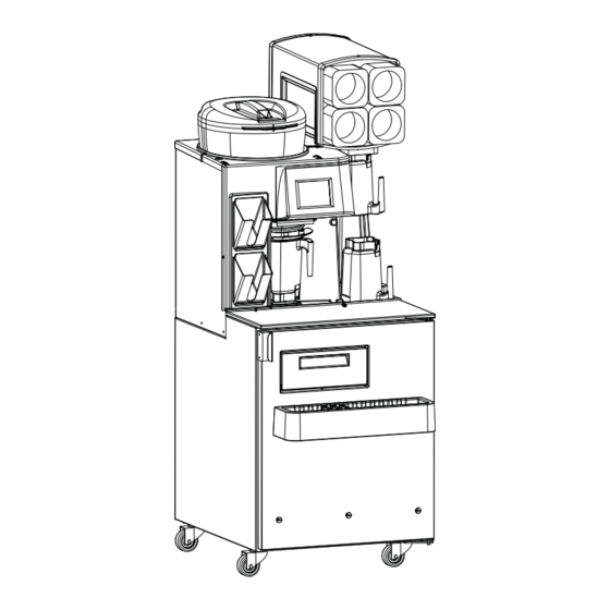
Blended Ice Machine
Multiplex Models MS-8
Service Manual
Manufactured exclusively for
McDonald's® By:
Manitowoc Foodservice
Tel. (888) 436-5442
Tel. (989) 773-7981
Fax (888) 779-2040
MS-8-1H, MS-8-1LH
MS-8-EH, MS-8-ELH
MS-8-AH, MS-8-ALH
MS-8-BH, MS-8-BLH
MS-8-CH, MS-8-CLH
MS-8-FH, MS-8-FLH
MS000A01, MS000A02
MS000A03, MS000A04
MS000A05, MS000A06
Blended Ice Machine
Multiplex
January 2012
Printed in
The United States of America
Advertisement
Table of Contents

Subscribe to Our Youtube Channel
Related Manuals for Manitowoc Multiplex Ms-8


Summary of Contents for Manitowoc Multiplex Ms-8
- Page 1 Blended Ice Machine Multiplex Models MS-8 Service Manual Manufactured exclusively for McDonald’s® By: Manitowoc Foodservice Tel. (888) 436-5442 Tel. (989) 773-7981 Fax (888) 779-2040 MS-8-1H, MS-8-1LH MS-8-EH, MS-8-ELH MS-8-AH, MS-8-ALH MS-8-BH, MS-8-BLH MS-8-CH, MS-8-CLH MS-8-FH, MS-8-FLH MS000A01, MS000A02 MS000A03, MS000A04...
- Page 2 Important Warning And Safety Information WARNING READ THIS MANUAL THOROUGHLY BEFORE OPERATING, INSTALLING, OR PERFORMING MAINTENANCE ON THE EQUIPMENT. WARNING FAILURE TO FOLLOW INSTRUCTIONS IN THIS MANUAL CAN CAUSE PROPERTY DAMAGE, INJURY OR DEATH. WARNING DO NOT STORE OR USE GASOLINE OR OTHER FLAMMABLE VAPORS OR LIQUIDS IN THE VICINITY OF THIS OR ANY OTHER APPLIANCE.
-
Page 3: Table Of Contents
Table of Contents General Information Model Numbers ............5 Serial Number Location . - Page 4 Table of Contents (continued) Component Check Procedures, continued Evaporator Fan ............42 Condenser Fan .
-
Page 5: General Information
Labor required to repair or replace defective This manual covers the Blended Ice Machine, model components is covered for three (3) years from the date numbers MS-8-1H, MS-8-1LH, MS-8-EH, MS-8-ELH, of original installation. MS-8-AH, MS-8-ALH, MS-8-BH, MS-8-BLH, MS-8- CH, MS-8-CLH, MS-8-FH, MS-8-FLH, MS000A01,... -
Page 6: Component Identifi Cation
Component Identifi cation Dispenser (1706175) Ice Hopper Lid (VMP00133) Touch Screen Manual Rinse Dispenser Button (1706142) Blender Rinse Location Whipped Blender Fill Cream Door Pitcher (000-187-0016) Product Syrup Rail Bins (1706194) (1706268) Syrup Rail Divider (1706195) Pull Out Tray (076-CDZ-0000) Part Description Number General System Overview... -
Page 7: Electrical
Breaker Voltage/Cycle MINIMUM CIRCUIT AMPACITY Numbers Amps Size The minimum circuit ampacity is used to help select MS-8-1H, the wire size of the electrical supply. (Minimum circuit MS-8-1LH, ampacity is not the Blended Ice Machine’s running amp MS-8-FH, 115/60/1 16.0 load.) The wire size (or gauge) is also dependent upon... -
Page 8: Clearance Requirements
Clearance Requirements Location The location selected for the Blended Ice Machine must Model Air Cooled meet the following criteria. 8" (20 cm) • The air temperature must be at least 40°F (4°C), but Sides 6" (15 cm) must not exceed 90°F (32°C), climate class 4. Back 6"... -
Page 9: General Maintenance Instructions
Maintenance and plastic scrub pad. Always rub with the grain of the steel. There are stainless steel cleaners available which can restore Door Gasket Maintenance and preserve the fi nish of the steels protective layer. Early signs of stainless steel breakdown are small pits and cracks. If this Door gaskets require regular cleaning to prevent mold and has begun, clean thoroughly and start to apply stainless steel mildew build up and also to retain the elasticity of the gasket. -
Page 10: Daily Preventive Maintenance Card
Clean Blended Ice Machine (BIM-8) Daily BE 23 D1 To break the bacteria cycle Time required 5 minutes to prepare 15 minutes to complete Time of day At close For 24-hour restaurants: During low-volume periods Hazard icons Chemicals Precaution: Hazard Communication Standard (HCS) – The procedures on this card include the use of chemical products. These chemical products will be highlighted with bold face letters followed by the abbreviation (HCS) in the tools portion of the procedure. - Page 11 Clean Blended Ice Machine (BIM-8) (continued) With the blender pitchers at Re-install all components. the 3-compartment sink, clean Blend pitchers, ice hopper lid, pitchers. syrup rails, drip pan and splash guard. Place one KAY Beverage Equipment Cleaner packet into the first pitcher and fill Clean with APSC the interior of with hot water from the back the blended ice machine with a...
-
Page 12: Weekly Preventive Maintenance Card
Clean Blended Ice Machine (BIM-8) Weekly BE 23 W1 To break the bacteria cycle Time required 10 minutes to prepare 50 minutes to complete Time of day At close For 24-hour restaurants: During low-volume periods Hazard icons Electricity Chemicals Sharp Objects/Surfaces Precaution: Hazard Communication Standard (HCS) –... - Page 13 Clean Blended Ice Machine (BIM-8) (continued) Remove product bins and Press Next. bags. The message window will Remove each product bag display: “Rinse of Strawberry Banana Line”, then change to from the product bin and the next flavor until all lines place in walk-in cooler.
- Page 14 Clean Blended Ice Machine (BIM-8) (continued) Lube each product line. Use clean sanitizer-soaked towel to clean inside of Use either Taylor Lube HP or hopper. Carpigiani Carpilube. Put a small amount of lube around Use caution when wiping near each product line. the shaver blade.
- Page 15 Clean Blended Ice Machine (BIM-8) (continued) With the blender pitchers at Clean with APSC the interior of the 3-compartment sink: the blended ice machine with a clean, sanitized towel Place one KAY Beverage dampened with KAY 5 Equipment Cleaner packet Sanitizer solution: into the first pitcher and fill with hot water from the back...
- Page 16 Clean Blended Ice Machine (BIM-8) (continued) Pour two full pitchers of hot Rinse the BIO-SHIELD® water from the back sink into dispenser. the dispenser. Rinse the BIO-SHIELD® dispenser with warm water and return the dispenser to the proper storage area. IMPORTANT! Do not use Quickly pour one packet of the drain for at least four...
-
Page 17: Operation
Operation Procedure to Make a Drink NOTE: Ice must be present in the ice bin and product must be connected and primed to produce a drink. Size and Option Touch Screen 3. Select drink options: - Select Return to view the previous screen. Drink Selection Touch Screen - The yogurt button toggles between including and leaving out the yogurt. -
Page 18: How To Replace A Product Bag
Procedure to Replace a Product Bag 8. Return product bin to its position in cabinet. These instructions can be found on the Touch Screen in the Help Menu under “Replace Product”. 1. Touchscreen will indicate the bag is empty “Drink making paused, check product supply”. -
Page 19: Shaver Blade Replacement
Shaver Blade Replacement WARNING: To reduce the risk of injury, unplug the unit before beginning any repair or upgrade work. WARNING: Shaver and Blender Blades are sharp! Handle with caution to avoid injury. NOTE: Actual components may differ slightly in appearance from those shown in this Update. Unplug the unit from its power source. -
Page 20: Energize Sequence Flowchart
Energize Sequence Flowchart 1/12... -
Page 21: Make A Drink Energized Component Flowchart
Make a Drink Energized Component Flowchart 1/12... - Page 22 MAKE A DRINK ENERGIZED COMPONENT FLOWCHART - CONTINUED 1/12...
- Page 23 1/12...
-
Page 24: Rinsing Energized Flowchart
Rinsing Energized Flow Chart Try a different pitcher Control board energizes water inlet valve coil Water valve opens Valve de-energizes after predetermined time period 1/12... - Page 25 Rinsing Energized Flow Chart errors / corrections Place pitcher in rinse position Replace magnet or pitcher Replace wire Pitcher magnet closes reed Switch doesn’t close switch Try a different pitcher Control Board energizes water Check for Replace inlet valve coil power at relay relay brd board...
-
Page 26: Manager's Menu Screen
Manager’s Menu Screen Service password is 89531. After selecting Managers Menu, the pass code The screen features: screen appears. • Update System Parameters • Scale Calibration Managers password is 3312 or 71360. • Periodic Maintenance The screen features: • Fault and Diagnostic History •... -
Page 27: Troubleshooting
Troubleshooting Display Assembly Symptom: Potential Cause: Remedy / Checks: No Power Verify that the machine is plugged into a working outlet that is rated for the Improper / machine. Disconnected Power Verify that the power switch is ON. Wiring If the power switch is ON, verify that LED17 and LED 18 of the I/O board are ON, I/O Board Display Assembly and LED15 (MICROPROCESSOR) is ON-Flashing. -
Page 28: Blender And Scale
Blender and Scale Symptom: Potential Cause: Remedy / Checks: No Power to Blender *Note: If the blender communication is good, LED14 on the I/O board will be ON. Blender Control Communication Error: Check power connections to Blender Control Blender Cable / “Communication Lost Check serial cable connection between blender control and I/O board. -
Page 29: Cooling
Cooling Symptom: Potential Cause: Remedy / Checks: Faulty Temperature See Product/Cabinet Thermistor debug section. Thermistor Compressor not turn- From the startup screen, select [Menu] à [Managers Menu]. ing off Enter code “89531”. I/O Board Select [Test I/O]. Cabinet Temperature The compressor relay should be OFF. Low / Product If the compressor is still ON, verify that LED1 on the I/O board is OFF. -
Page 30: Ice Shaver/Ice Bin Cover
Ice Shaver / Ice Bin Cover Symptom: Potential Cause: Remedy / Checks: Ice Bin Lid not in place. Ensure that the Ice Bin Lid is positioned properly on the Ice Bin. See “Ice Bin Lid” for debugging Ice Bin Lid issues. Ice Shaver breaker Check the breaker at the rear of the machine. -
Page 31: Product Dispensing
Product Dispensing Symptom: Potential Cause: Remedy / Checks: Air line disconnected Verify that a pressurized air line is connected to the air inlet on the back of the Insufficient air pressure system. Regulator Bad Verify that the air regulator at the rear of the machine is between TBD and TBD psi. -
Page 32: Rinsing And Water Dispensing
Rinsing and Water Dispensing Symptom: Potential Cause: Remedy / Checks: Water is not connected or turned Turn on the water source and ensure that all water connections are tight. Ensure that the water pressure is above 30 psi. Ensure water is connected and turned ON (water pressure gauge) Blend container is not properly... -
Page 33: Refrigeration Operation
Refrigeration Operation Maximum Compressor Run Time After 180 minutes of cumulative compressor run time, Default temperature setpoint = 36°F (2.2°C) with a 4°F the compressor will be de-energized for fi fteen (15) (2.2°C) Differential minutes. Normal Operation High Temp Alarm The microprocessor control board controls the cabinet High temp alarm will display when product thermistor temperature based on the input received from the... -
Page 34: Will Not Run Flowchart
Will Not Run Flowchart 1/12... - Page 35 Will Not Run Flowchart, continued 1/12...
-
Page 36: Weight Beam Diagnostic Flowchart
Weight Beam Diagnostic Flowchart 1/12... -
Page 37: Ice Shaver Will Not Run Flowchart
Ice Shaver Will Not Run Flowchart 1/12... -
Page 38: Component Check Procedures
Component Check Procedures ON/OFF Rocker Switch Transformer FUNCTION FUNCTION The switch is used to energize and de-energize the Reduces primary voltage to secondary voltage. Blended Ice Machine. Steps down voltage from 120 or 230 VAC to 24 VDC. SPECIFICATIONS SPECIFICATIONS Double-pole, Double-throw switch. -
Page 39: Control Board Fuse
Control Board Fuse IO (Input/Output) Board FUNCTION FUNCTION The control board fuse stops Blended Ice Machine Routes signals from sensors to the microprocessor operation if electrical components fail, causing high amp control board. draw. Opens and closes relays based on the signals it receives from the microprocessor control board. -
Page 40: Lcd Touchscreen & Microprocessor Control Board
LCD Touchscreen & Microprocessor Cabinet Temperature Thermistor Control Board FUNCTION FUNCTION Supplies input to control board to indicate cabinet temperature. The control board energizes and de- Touch screen is the user interface with the machine and energizes the compressor based on input from this sends input to the control board. -
Page 41: Product Chase Temperature Thermistor
Product Chase Temperature Thermistor Chase Fan FUNCTION FUNCTION Supplies input to control board to indicate chase Moves cool air from the cabinet through the tubing temperature. The control board energizes error warning chase to maintain cabinet temperature in the beverage based on input from this thermistor. -
Page 42: Evaporator Fan
Evaporator Fan Ice Bin Lid Microswitch FUNCTION FUNCTION Circulates air across the evaporator and throughout the Prevents operation of machine with ice bin lid removed. cabinet interior. Two micro switches are used, one micro switch signals the control board to initiate a failure screen and the SPECIFICATIONS second micro switch prevents the shaver motor from 120/60/1 .38 amp... -
Page 43: Product Pump
Product Pump Shaver Motor FUNCTION FUNCTION Transfers product from bag to pitcher. Turns shaver wheel to supply shaved ice. SPECIFICATIONS SPECIFICATIONS Pressure operated, requires a minimum pressure of 40 Shaver motor has a circuit breaker and diode bridge PSI (276 kPa). Maximum pressure is 90 PSI (621 kPa). block. -
Page 44: Circuit Breaker
Circuit Breaker Manual Rinse Push Button FUNCTION FUNCTION Disconnects power to the shaver motor if the amperage Allows manual rinsing of containers without requiring a is too high. magnet to actuate the water valve. SPECIFICATIONS SPECIFICATIONS 3 amp 250 volts 50/60 cycle SPST push button switch CHECK PROCEDURE CHECK PROCEDURE... -
Page 45: Compressor Electrical Diagnostics
Compressor Electrical Diagnostics DIAGNOSING CAPACITORS If the compressor attempts to start, or hums and trips THE COMPRESSOR DOES NOT START OR WILL the overload protector, check the starting components TRIP REPEATEDLY ON OVERLOAD. before replacing the compressor. Check Resistance (Ohm) Values Visual evidence of capacitor failure can include a bulged Compressor windings can have very low ohm values. -
Page 46: Discharge Pressure High Checklist
Discharge Pressure High Checklist Suction Pressure High Checklist Improper Installation Improper Installation • Refer to “Installation/Visual Inspection Checklist” • Refer to “Installation/Visual Inspection Checklist” Air Condenser Discharge Pressure • Dirty condenser fi ns • Discharge pressure is too high and is affecting low side •... -
Page 47: Recovery/Evacuation
Do not purge refrigerant to the atmosphere. Capture Recovery/Evacuation refrigerant using recovery equipment. Follow the 1. Place the rocker switch in the OFF position. manufacturer’s recommendations. 2. Install manifold gauges, charging scale, and Important recovery unit or two-stage vacuum pump. Multiplex assumes no responsibility for the use of 3. -
Page 48: Assembly & Replacement Parts List
Bracket, Shy Cord Hook, Small MS-8-CH 000-BN5-0047 000-CD0-0001 000-BIC-0016 1706268 Bin, Product, Horizontal MS-8-EH 000-BN5-0006 000-CD0-0001 000-BIC-0016 9321041 Nut, Acorn, #10-24, Chrome Plated MS-8- FH 000-BN5-0004 000-CD0-0000 000-BIC-0040 076-CDZ-0000 Pan, Product Drip MS000A01 & 000-BN5-0006 000-CD0-0001 000-BIC-0044 270-CI5-0000 Support, Cnt, Bin MS000A02... -
Page 49: Top
3547784 Regulator, Pressure, Water MS-8-CH 2195102 272-BZZ-0002 3547785 Regulator, Water, CO2 MS-8-EH 2195102 272-BZZ-0002 3547828 Valve, Solenoid, Water, Double MS-8- FH 2195105 000-BIC-001G 359-CCJ-0003 Panel, Right, Upper MS000A01 & 2195102 272-BZZ-0002 027-CCZ-0002 Cover, Electric Box, Upper MS000A02 1706126 Bracket, Pitcher, Rinse MS000A03 &... -
Page 50: Duct Outlet
MS-8-BH 1706172 1706284 Bracket, Splash, Inner, Lower MS-8-CH 1706172 1706200 Bracket, Splash, Inner, Upper MS-8-EH 1706172 270-CCQ-0006 Bracket, Dispenser Head MS-8- FH 1706370 372-CCQ-0009 Plate, Ambient H20 MS000A01 & 1706172 000-BIC-0010-S Splash Shield Assembly MS000A02 MS000A03 & 1706172 MS000A04 MS000A05 &... -
Page 51: Miscellaneous
Top Valve & Pump Assembly Lower Pump Assembly Part Number Description Part Number Description Common To All Models Common To All Models 380-CD5-0003 Cover, Evap, Smoothie 3239655 Pump, Flojet, NSF 3239655 Pump, Flojet, NSF 3239657 Solenoid Valve Manifold, Mac 3239657 Solenoid Valve Manifold, Mac Miscellaneous Parts Part Number... -
Page 52: Vitamix Assembly
MS-8-BH VMP00149 VMP00150 3239670 VMP00151 VMP00145 MS-8-CH VMP00149 VMP00150 3239670 VMP00151 VMP00145 MS-8-EH VMP00149 VMP00150 3239670 VMP00151 VMP00145 MS-8- FH VMP00125 3239676 VMP00139 VMP00112 MS000A01 & 3239681 VMP00145 MS000A02 MS000A03 & 3239681 VMP00145 MS000A04 MS000A05 & VMP00125 3239681 VMP00112 MS000A06... -
Page 53: Condensing Unit
2162720 3526994 0074057 MS-8-BH 2162720 3527071 0074057 MS-8-CH 2162720 3526988 3547588 (.036”ID) MS-8-EH 3516460 3516452 3516451 2162720 3526994 0074057 MS-8- FH 3516443 3516446 2194787 2162717 3526997 0074057 MS000A01 & 3516460 3516452 3516451 2162720 3526994 0074057 MS000A02 MS000A03 & 3516460 3516452... -
Page 54: Refrigerant Recovery/Evacuation & Charging Procedures
Refrigerant Recovery/Evacuation & Charging Procedures Charging Procedures System Contamination Cleanup The charge is critical on all Multiplex Blended Ice General Machine. Use a scale to ensure the proper charge is This section describes the basic requirements for installed. A quick disconnect is required for the high side restoring contaminated systems to reliable service. -
Page 55: Mild System Contamination Cleanup Procedure
CONTAMINATION/CLEANUP CHART leak detector after system charging to be sure there are no leaks. Symptoms/Findings Required Cleanup Procedure 1. Charge the system with the proper refrigerant to the nameplate charge. • No symptoms or suspicion of contamination Normal evacuation/recharging procedure 2. -
Page 56: R-290 Service Procedure
2. NO SMOKING 3. Disconnect all power to the unit being serviced. Models using R404A refrigerant Air-Cooled 4. Move the unit to be serviced to a well ventilated MS-8-1H, MS-8-1LH, 12 oz (340g) area. MS-8-AH, MS-8-ALH, MS-8-EH, MS-8-ELH, 5. Check for leaks using a calibrated Hydro Carbon MS-8-FH, MS-8-FLH, leak detector. -
Page 57: Specifi Cations/Wiring Diagrams/Schematics
Specifi cations/Wiring Diagrams/Schematics Wiring Diagram MS-8-1H, MS-8-1LH MS-8-FH, MS-8-FLH MS000A05, MS000A06 1/12... -
Page 58: Blender Scale & Shaver Schematics
Wiring Diagram MS-8-AH, MS-8-ALH MS-8-BH, MS-8-BLH MS-8-CH, MS-8-CLH MS-8-EH, MS-8-ELH MS000A01, MS000A02 MS000A03, MS000A04 1/12... - Page 59 Blender Scale Schematic Shaver Schematic 1/12...
-
Page 60: Electronic Control Board
Electronic Control Board 1. LCD Ribbon Connector • Verify strip is even. There is a line on the strip, it needs to be parallel with the edge of the lock • Lift lock up to 90° to remove and reinsert strip connector 2. -
Page 61: Bim Warranty Guidelines
BIM Warranty Guidelines Repair Repair Hours Calibration ......1 Repair Blender Rotor Jam .....1 Replace Advanced Bearing Assembly Pulley . -
Page 62: Notes
Notes 1/12... - Page 63 Notes 1/12...
- Page 64 Multiplex Thank you for choosing Manitowoc Foodservice! Help is a phone call away. Help our team of professional, courteous customer service reps by having your model number and serial number available at the time of your call (888) 436-5442. Model: ____________________ S/N: ___________________...
Need help?
Do you have a question about the Multiplex Ms-8 and is the answer not in the manual?
Questions and answers