U-Line CLR1215 User Manual
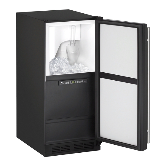
15" clear ice maker
Hide thumbs
Also See for CLR1215:
- User manual (62 pages) ,
- User manual & service manual (53 pages) ,
- Quick start manual (17 pages)

Related Manuals for U-Line CLR1215


Summary of Contents for U-Line CLR1215
- Page 1 USER GUIDE SAFETY • INSTALLATION & INTEGRATION • OPERATING INSTRUCTIONS • MAINTENANCE • SERVICE RIGHT PRODUCT. RIGHT PLACE. RIGHT TEMPERATURE. SINCE 1962. 1000 Series CLR1215 15" Clear Ice Maker • •...
-
Page 2: Table Of Contents
USER GUIDE u-line.com SAFETY • INSTALLATION & INTEGRATION • OPERATING INSTRUCTIONS • MAINTENANCE • SERVICE Contents Intro Maintenance Cleaning Safety Safety and Warning Cleaning Condenser Disposal Extended Non-Use Installation Service Environmental Requirements Accessories Electrical Troubleshooting Cutout Dimensions Warranty Product Dimensions... - Page 3 1. U-Line Customer Care must be contacted immediately at +1.800.779.2547. 2. Service or repairs performed on the unit without prior written approval from U-Line is not permitted. If the unit has been altered or repaired in the field without prior written approval from U-Line, claims will not be eligible.
-
Page 4: Safety And Warning
USER GUIDE u-line.com SAFETY • INSTALLATION & INTEGRATION • OPERATING INSTRUCTIONS • MAINTENANCE • SERVICE Safety and Warning NOTICE Please read all instructions before installing, operating, or servicing the appliance. Use this appliance for its intended purpose only and follow... - Page 5 USER GUIDE u-line.com SAFETY • INSTALLATION & INTEGRATION • OPERATING INSTRUCTIONS • MAINTENANCE • SERVICE Product Disposal and Recycling DANGER RISK OF CHILD ENTRAPMENT. Before you throw away your old refrigerator or freezer, take off the doors and leave shelves in place so children may not easily climb inside.
-
Page 6: Environmental Requirements
USER GUIDE u-line.com SAFETY • INSTALLATION & INTEGRATION • OPERATING INSTRUCTIONS • MAINTENANCE • SERVICE Environmental Requirements This unit is designed to operate between 50°F (10°C) and 100°F (37°C). Higher ambient temperatures may reduce the unit’s ability to reach low temperatures and/or reduce ice production on applicable models. -
Page 7: Electrical
USER GUIDE u-line.com SAFETY • INSTALLATION & INTEGRATION • OPERATING INSTRUCTIONS • MAINTENANCE • SERVICE Electrical WARNING SHOCK HAZARD — Electrical Grounding Required. Never attempt to repair or perform maintenance on the unit until the electricity has been disconnected. Never remove the round grounding prong from the plug and never use a two-prong grounding adapter. -
Page 8: Cutout Dimensions
SAFETY • INSTALLATION & INTEGRATION • OPERATING INSTRUCTIONS • MAINTENANCE • SERVICE Cutout Dimensions PREPARE SITE Your U-Line product has been designed for either free- standing or built-in installation. When built-in, your unit does not require additional air space for top, sides, or rear. -
Page 9: Product Dimensions
USER GUIDE u-line.com SAFETY • INSTALLATION & INTEGRATION • OPERATING INSTRUCTIONS • MAINTENANCE • SERVICE Product Dimensions Not Including Handle 23-1/4" (591 mm) 34-1/8" to 35-1/8" (867 mm to 892 mm) 3-9/16" (91 mm) 14-15/16" (379 mm) Product Dimensions 1... -
Page 10: Side By Side Installation
USER GUIDE u-line.com SAFETY • INSTALLATION & INTEGRATION • OPERATING INSTRUCTIONS • MAINTENANCE • SERVICE Side by Side Installation 3. Place bracket over holes and attach to unit with two screws removed in step 2 using a slotted screwdriver. Two units may be installed side by side. -
Page 11: Water Hookup
USER GUIDE u-line.com SAFETY • INSTALLATION & INTEGRATION • OPERATING INSTRUCTIONS • MAINTENANCE • SERVICE Water Hookup Do not use Teflon tape or joint compound on the water fitting. The rubber washer provides an PREPARE PLUMBING adequate seal. Other materials could cause blockage of the valve. - Page 12 USER GUIDE u-line.com SAFETY • INSTALLATION & INTEGRATION • OPERATING INSTRUCTIONS • MAINTENANCE • SERVICE Water Hookup 2...
-
Page 13: Drain
DRAIN CONNECTION CAUTION With Trap and Vent Proper Drain If your U-Line unit did not come with a factory installed drain pump you must use a gravity A gravity drain may be used if: style drain connection. For assistance in Drain line has at least a 1"... - Page 14 (Optional Hook-Up) requirements for a gravity drain, you may have ordered a pre-installed U-Line P60 drain pump. Waste If you need to install a P60 drain pump into your unit, (see Valve “Drain Pump”).
-
Page 15: Drain Pump
Ice Machine ships with before installing the unit. discharge tube installed.) • The U-Line P60-00 drain pump is designed to be used 5. 2x Vent tube Zip Ties exclusively on the U-Line Clear Ice Machine and is UL recognized only for use on the U-Line Clear Ice 6. - Page 16 USER GUIDE u-line.com SAFETY • INSTALLATION & INTEGRATION • OPERATING INSTRUCTIONS • MAINTENANCE • SERVICE Note: Slide clamp on hose end before installing hose. Do not tighten clamp until pump and hoses have been installed. 6. Install the 3 hoses and hose...
- Page 17 USER GUIDE u-line.com SAFETY • INSTALLATION & INTEGRATION • OPERATING INSTRUCTIONS • MAINTENANCE • SERVICE WARNING The back panel serves as a guard. Do not put your hands inside the ice machine cabinet or attempt to touch any components except the discharge tube during testing.
-
Page 18: Anti-Tip Bracket
USER GUIDE u-line.com SAFETY • INSTALLATION & INTEGRATION • OPERATING INSTRUCTIONS • MAINTENANCE • SERVICE Anti-Tip Bracket 1. Slide unit out so screws on top of unit are easily accessible. 2. Remove the two screws from the opposite side of the hinge assembly using a slotted screwdriver (see below). -
Page 19: General Installation
USER GUIDE u-line.com SAFETY • INSTALLATION & INTEGRATION • OPERATING INSTRUCTIONS • MAINTENANCE • SERVICE General Installation INSTALLATION 1. Open the water supply valve in the main water source. LEVELING INFORMATION 1. Use a level to 2. Plug in the power cord. -
Page 20: Grille / Plinth Installation
USER GUIDE u-line.com SAFETY • INSTALLATION & INTEGRATION • OPERATING INSTRUCTIONS • MAINTENANCE • SERVICE Grille - Plinth Installation REMOVING AND INSTALLING GRILLE WARNING Disconnect electric power to the unit before removing the grille. WARNING DO NOT touch the condenser fins (4). The condenser fins are SHARP and can be easily damaged. -
Page 21: Door Swing
USER GUIDE u-line.com SAFETY • INSTALLATION & INTEGRATION • OPERATING INSTRUCTIONS • MAINTENANCE • SERVICE Door Swing Wall Wall 1/4" Min. 2-1/8" Min. (6 mm) (54 mm) Door Swing Door Swing Units have a zero clearance for the door to open 90°, when installed adjacent to cabinets. -
Page 22: Door Stop
Door Stop NOTE: Threaded pin will be inserted from the bottom. Your U-Line unit was shipped to you with the optional 90° pin(s). (Models that are 15" wide include 1 pin. Models that are 24" wide include 2 pins.) The unit’s door will open freely without a fixed opening angle limitation. -
Page 23: Door Adjust
USER GUIDE u-line.com SAFETY • INSTALLATION & INTEGRATION • OPERATING INSTRUCTIONS • MAINTENANCE • SERVICE Door Adjustments DOOR ALIGNMENT AND ADJUSTMENT Align and adjust the door if it is not level or is not sealing properly. If the door is not sealed, the unit may not cool properly, or excessive frost may form in the interior. - Page 24 USER GUIDE u-line.com SAFETY • INSTALLATION & INTEGRATION • OPERATING INSTRUCTIONS • MAINTENANCE • SERVICE 4. Remove four screws from hinge holes on the opposite 2. Remove gasket center strip and apply in-line with new side. Reinstall into holes where the hinge was opening (approximately 2"...
-
Page 25: First Use
USER GUIDE u-line.com SAFETY • INSTALLATION & INTEGRATION • OPERATING INSTRUCTIONS • MAINTENANCE • SERVICE First Use All U-Line controls are preset at the factory. Initial startup requires no adjustments. NOTICE U-Line recommends discarding the ice produced during the first two to three hours of operation to avoid possible dirt or scale that may dislodge from the water line. -
Page 26: Control Operation
USER GUIDE u-line.com SAFETY • INSTALLATION & INTEGRATION • OPERATING INSTRUCTIONS • MAINTENANCE • SERVICE Control Operation Alert Up Down Light Power Clean CONTROL FUNCTION GUIDE FUNCTION COMMAND DISPLAY/OPTIONS ON/OFF Press and release Unit will immediately turn ON or OFF. -
Page 27: Ice
USER GUIDE u-line.com SAFETY • INSTALLATION & INTEGRATION • OPERATING INSTRUCTIONS • MAINTENANCE • SERVICE Cube Types ICE CUBE THICKNESS ADJUSTMENT 1/4" TO 1/2" 1/16" TO 1/8" Interval - As Required (6.4 mm to 12.7 mm) (1.6 mm to 3.2 mm) -
Page 28: Sabbath Mode
Sabbath Mode Select Down U-Line Clear Ice Machine models are Star-K certified and can be used during the Sabbath. View a full list of Star-K certified U-Line units at www.star-k.org. To prepare the unit for the Sabbath: 1. Press and hold the until the unit turns off. -
Page 29: Airflow And Product Loading
USER GUIDE u-line.com SAFETY • INSTALLATION & INTEGRATION • OPERATING INSTRUCTIONS • MAINTENANCE • SERVICE Airflow and Product Loading NOTICE The unit requires proper airflow to perform at its highest efficiency. Do not block the front grille at any time, or the unit will not perform as expected. -
Page 30: Cleaning
For best results use Claire Stainless Steel Rinse the interior using a soft sponge and clean water. Polish and Cleaner, which can be purchased from U-Line Corporation (Part Number 173348). Comparable products are acceptable. Frequent cleaning will remove surface Do not use any solvent-based or abrasive contamination that could lead to rust. - Page 31 Water trough before use. 6. Clean the Interior Bin as follows: U-Line Ice Machine Cleaner is used to remove lime scale and other mineral deposits. Refer to the following steps to initiate the self-cleaning cycle. • Dilute one packet of CLR cleaner into two quarts of water.
- Page 32 Due to variations in water quality or inadequate maintenance your unit may become excessively coated in lime scale or calcium. U-Line offers a cost effective refresh kit which replaces many interior components and will return your unit to like new condition. Refresh kits may be ordered from your local distributor and installed by your local service company.
-
Page 33: Cleaning Condenser
USER GUIDE u-line.com SAFETY • INSTALLATION & INTEGRATION • OPERATING INSTRUCTIONS • MAINTENANCE • SERVICE Cleaning Condenser INTERVAL - EVERY SIX MONTHS To maintain operational efficiency, keep the front grille free of dust and lint, and clean the condenser when necessary. -
Page 34: Extended Non-Use
SAFETY • INSTALLATION & INTEGRATION • OPERATING INSTRUCTIONS • MAINTENANCE • SERVICE Extended Non-Use VACATION/HOLIDAY, PROLONGED SHUTDOWN For questions regarding winterization please call U-Line at 1.800.779.2547. The following steps are recommended for periods of extended non-use: CAUTION 1. Remove all consumable content from the unit. -
Page 35: Accessories
USER GUIDE u-line.com SAFETY • INSTALLATION & INTEGRATION • OPERATING INSTRUCTIONS • MAINTENANCE • SERVICE Accessories 80-51002-00 37050 23054-01 Accessories - Clear Ice Accessories - Clear Ice Accessories - Stainless Steel Maker Refresh Kit Machine Cleaner - 1 Box of PRO Style Door Handle, US$98.99... -
Page 36: Troubleshooting
• Compressor: The compressor makes a hum or pulsing sound that may be heard when it operates. BEFORE CALLING FOR SERVICE If you think your U-Line product is malfunctioning, read • Evaporator: Refrigerant flowing through an evaporator the OPERATING INSTRUCTIONS section of this guide to may sound like boiling liquid. - Page 37 USER GUIDE u-line.com SAFETY • INSTALLATION & INTEGRATION • OPERATING INSTRUCTIONS • MAINTENANCE • SERVICE CONTROL OPTIONS On/Off: Press power key and unit will turn off or on. Light: When applicable (Table: Basic Settings) hit the light key and light will remain on for 3 hours.
-
Page 38: Warranty
God, such as fire, floods, wind and U-Line product to be free from defects in materials and lightning; damages incurred or resulting from shipping, workmanship for a period of five years from the date of improper installation, unauthorized modification, or purchase. - Page 39 7. If a product defect is discovered during the applicable warranty period, you must promptly notify either U-Line at 8900 N. 55th Street, Milwaukee, Wisconsin 53223 USA or at +1.800.779.2547 or the dealer from whom you purchased the product. In no event shall such notification be received later than 30 days after the expiration of the applicable warranty period.
Need help?
Do you have a question about the CLR1215 and is the answer not in the manual?
Questions and answers