Table of Contents
Advertisement
®
Installation, Operation and Maintenance Manual
Please read and save these instructions for future reference. Read carefully before attempting to assemble, install,
operate or maintain the product described. Protect yourself and others by observing all safety information. Failure
to comply with instructions could result in personal injury and/or property damage!
WARNING
To reduce the risk of fire, electric shock, or injury
to persons, observe the following:
• Use this unit only in the manner intended by the
manufacturer.
• Before servicing or cleaning unit, switch power off
at service panel and lock the service disconnecting
means to prevent power from being switched on
accidentally. When the service disconnecting means
cannot be locked, securely fasten a prominent
warning device, such as a tag, to the service panel.
• Installation work and electrical wiring must be
done by a qualified person(s) in accordance with all
applicable codes and standards, including fire rated
construction codes and standards.
• Sufficient air is needed for proper combustion
and exhausting of gases through the flue
(chimney) of fuel burning equipment to prevent
backdrafting. Follow the heating equipment
manufacturer's guideline and safety standards such
as those published by the National Fire Protection
Association (NFPA), and the American Society
of Heating, Refrigeration and Air Conditioning
Engineers (ASHRAE), and the local code authorities.
• When cutting or drilling into wall or ceiling, do not
damage electrical wiring and other hidden utilities.
• To reduce the risk of fire or electric shock, do
not use this range hood with an additional speed
control device.
• Ducted fans must always be vented to the
outdoors.
• To reduce the risk of fire, use only metal ductwork.
• Use with approved wiring only.
• This unit must be grounded.
®
WARNING
To reduce the risk of range top grease fire:
• Never leave surface units unattended at high
settings. Boilovers cause smoking and greasy
spillovers that may ignite. Heat oils slowly on low or
medium settings.
• Always turn hood ON when cooking at high heat or
when cooking flaming foods.
• Clean ventilation fans frequently. Grease should not
be allowed to accumulate on fan or filter.
• Use proper pan size. Always use cookware
appropriate for the size of the surface element.
To reduce the risk of injury to persons in the event
of a range top grease fire, observe the following:*
• SMOTHER FLAMES with a close-fitting lid, cookie
sheet, or metal tray, then turn off the burner. BE
CAREFUL TO PREVENT BURNS. If the flames do
not go out immediately, EVACUATE AND CALL THE
FIRE DEPARTMENT.
• NEVER PICK UP A FLAMING PAN. You may be
burned.
• DO NOT USE WATER, including wet dishcloths or
towels - violent steam explosion will result.
* Based on "Kitchen Fire Safety Tips" published by
NFPA.
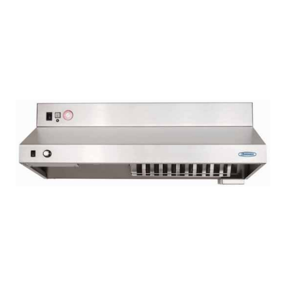
Model GRRS
Fire Ready Hood
1
Fire Ready Hood
Advertisement
Table of Contents

Related Manuals for Greenheck GRRS


Summary of Contents for Greenheck GRRS
- Page 1 Model GRRS Fire Ready Hood ® Installation, Operation and Maintenance Manual Please read and save these instructions for future reference. Read carefully before attempting to assemble, install, operate or maintain the product described. Protect yourself and others by observing all safety information. Failure...
-
Page 2: Table Of Contents
Fans ........6 the responsibility of Greenheck Fan Corporation. -
Page 3: Model Number Code
Model Number Code Exploded View GRRS - 30 - F - E GRRS - 30 - F - E Electrical Disconnect Recirculating Vent (Black Tape) (recirculating model) Type Type Range Disconnect Type Range Disconnect Type 110 VAC Power Supply Extinguisher... -
Page 4: Sample Installations
Sample Installations Roof Cap (by others) 10 in. Ductwork 7 in. to 10 in. Transition 7 in. to 10 in. Transition Inline Duct Fan (provided) Wall Mount Fan Box Wall Mount Fan Box with Access Cover for with Access Cover for Service and Mounting Service and Mounting (provided) -
Page 5: Preparing The Install Location
Preparing the Install Location Mounting Bracket - The mounting bracket and hood must be centered over the range. If the range is not in place, the center marking should be relative to it’s final position. Refer to page 7 for bracket mounting points, rear access holes and access points. -
Page 6: Fans
Fans Accessories For inline fans and exterior wall fans, fan location and Location restrictions will apply if the hood system proper mounting will be required. supplied is provided with any of the optional accessories: If the hood system is configured for front recirculation discharge or rear discharge and NFPA 101 compliance, •... -
Page 7: Installation Installation Elevation
Installation Installation Elevation A. Hood (30 or 36 inches) B. Appliance (for reference purposes) C. Range Disconnect - electric, gas or dual (optional) D. Gas Range Element Disconnect (not shown) E. The ClockBox. Range Element Time-Out System (optional) F. Handicapped Accessible Control Box (optional) G. -
Page 8: Installing Hood Onto Mounting Bracket
Installing Hood onto Mounting Bracket 4. Remove the safety pin - identified with the yellow CAUTION flag from the trigger on top of the NOTE extinguisher bottle. Install manual pull station, if provided, before arming the system. Safety Pin 1. Lift hood onto mounting bracket and seat the lower tabs of the mounting bracket into slots in back of hood. -
Page 9: Installing The Fan
Installing Fan (if applicable) Wall Mounted Fan Inline Fasten the fan box to an external wall via the four Install fan vertically in ductwork running between the unit and roof cap. 0.27-inch mounting holes. Run electrical through the 0.81-inch hole towards the For best results, use as few elbows or transitions as top right corner of the box. -
Page 10: Range Element Disconnect Installation Gas Disconnect Valve
Range Element Disconnect Installation Gas Disconnect Valve (if applicable) Electrical Disconnect Box (if applicable) The gas solenoid is designed for use with 3/4-inch NPT 1. Cut a hole in the drywall for the relay box; refer to pipe. Be sure to note the “IN” and “OUT” ends of the the submittal for dimensions. -
Page 11: Installing Accessories
Installing Accessories Step 3: Install Cable and Pin to hood Refer to your submittal for installation dimensions of these accessories. Thread the cable through the conduit, with the pin reaching the unit. Remove the grease filter. In the upper ClockBox (optional) right corner, find the two pulleys as illustrated. -
Page 12: Electrical Installation Main Control Power
Hood Supply 110-120 VAC 15A Metal clad wire from 110-120 VAC supply line 12/2 8 ft length, marked with red tape supplied by Greenheck Run metal clad wire from junction box on mounting plate to power disconnect box through wall... -
Page 13: Electric Disconnect Box
Electric Disconnect Box (if applicable) Provided by Greenheck L1 208-220 VAC Black Hot Power Disconnect Box 50AMP 250V By others Provided by others 8” x 6” x 4” L3 208-220 VAC Red Hot NEMA 14-50 T1 208-220 VAC Black Hot... -
Page 14: Inline/Wall Mount Fan
Inline/Wall Mount Fan Power (if applicable) Twenty-five (25) feet of plenum rated wire is provided with both the inline fan and wall mounted fan option. The fan needs to be connected with the provided connector within the hood controls. See wiring diagram on page 15 for wiring information. -
Page 15: Wiring Diagram
Wiring Diagram Description Value ClockBox 2 HR Controller Fuse 1 AMP Fast Blow Fan Fuse 2 AMP Slow Blow Dual Disconnect 1 AMP Slow Blow Disconnect Fuse 0.5 AMP Slow Blow Main Fuse 8 AMP Slow Blow ClockBox Fuse 8 AMP Slow Blow Main Power Connector Fan Connector Main Power Switch... -
Page 16: Operation
Operation - How it Works Environmental Monitoring / Pre-Suppression Functions The GRRS functions as a standard ventilation range The controller operating system is designed to enhance hood with the added capability to suppress stove top the functionality of the unit and the safety of the cooking fires. -
Page 17: Accessing The Internal Components
• Be careful while working with the unit in the service positions. position. Release of the cable system or applying All GRRS models have been configured as a stand force to the tank valve assembly may cause alone unit mounted to a wall plate. As such, the unit discharge of the tank. -
Page 18: Test Tank And Demonstration
Test Tank and Demonstration Once the hood has been installed, it may be necessary B. Manual Pull Kit (if installed) or desired to test the unit with a test tank filled with Raise the unit to its operational position after the test pressurized nitrogen (optional). -
Page 19: Controller Schematic
Controller Schematic On the controller, there are two rows of LED indicators PROG. ERR. Status display next to the X (inputs) and two rows of LED’s on the Y area (outputs). Input/output Input Scenario display Label Function State Hose in place Hose PROG. -
Page 20: Self-Monitoring System
Self-Monitoring System These functions are to be checked at start-up. Low Pressure Low Temperature Switches HOW TO TEST FUNCTION HOW TO TEST FUNCTION a. Unplug one of the wire terminal connections a. Use heat gun on either left or right low temp switch. attached to the pressure switch. -
Page 21: After An Actuation
After an Actuation How to Reset the Suppression System The fire suppression system must be recharged and Resetting and testing release mechanisms, remote restored to service immediately after any discharge for pull, and fusible links. continued fire suppression protection. Reset detection system by completing the following steps: WARNING 1. - Page 22 The pressure gauge is directly plumbed to the wet chemical tank valve assembly and indicates the pressure status of the nitrogen in the tank. The tank includes a pressure switch that closes if pressure is in the “green” or normal operation range. Resetting Gas Shut-Off Valve Before the gas supply is turned back on, extinguish any open flames and turn off all burners and any electrical or...
-
Page 23: Maintaining The System
To replace, make Replacement caps and nozzle O-rings are available sure the light switch is in the “OFF” position and then from Greenheck or through your representatives. gently unscrew the bulb. (Bulb: 60A15/TF) WARNING Removing the Extinguisher Tank The protective caps stay on the nozzles at all times. -
Page 24: Service And Recertification Schedule
Safety glasses must be worn whenever service operations are performed. Our Commitment As a result of our commitment to continuous improvement, Greenheck reserves the right to change specifications without notice. Specific Greenheck product warranties are located on greenheck.com within the product area tabs and in the Library under Warranties.
Need help?
Do you have a question about the GRRS and is the answer not in the manual?
Questions and answers