Table of Contents
Advertisement
®
Installation, Operation and Maintenance Manual
Please read and save these instructions. Read carefully before attempting to assemble, install, operate or maintain the
product described. Protect yourself and others by observing all safety information. Failure to comply with instructions
could result in personal injury and/or property damage! Retain instructions for future reference.
Please record the Serial, Model #, and Mark for the hood and other equipment for future reference.
Serial #: _______________________
Serial #: _______________________
Serial #: _______________________
Serial #: _______________________
Serial #: _______________________
Serial #: _______________________
Serial #: _______________________
Serial #: _______________________
Serial #: _______________________
Serial #: _______________________
Serial #: _______________________
1
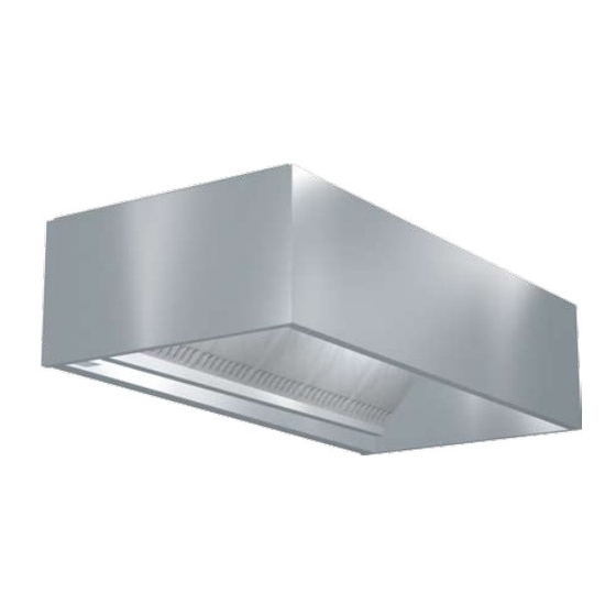
Canopy Hood
Model #: ______________________
Model #: ______________________
Model #: ______________________
Model #: ______________________
Model #: ______________________
Model #: ______________________
Model #: ______________________
Model #: ______________________
Model #: ______________________
Model #: ______________________
Model #: ______________________
Canopy Type Kitchen Hoods
Mark: _________________
Mark: _________________
Mark: _________________
Mark: _________________
Mark: _________________
Mark: _________________
Mark: _________________
Mark: _________________
Mark: _________________
Mark: _________________
Mark: _________________
PN 452413
Advertisement
Table of Contents

Related Manuals for Greenheck 452413


Summary of Contents for Greenheck 452413
- Page 1 Model #: ______________________ Model #: ______________________ Model #: ______________________ Model #: ______________________ Model #: ______________________ Model #: ______________________ Model #: ______________________ Model #: ______________________ PN 452413 Mark: _________________ Mark: _________________ Mark: _________________ Mark: _________________ Mark: _________________ Mark: _________________ Mark: _________________...
-
Page 2: Table Of Contents
Table of Contents Receiving and Handling ............. 4 Storage . - Page 3 Table of Contents Maintenance ..............32 Grease Grabber™...
-
Page 4: Receiving And Handling
Receiving and Handling Upon receiving the equipment, check for both obvious and hidden damage. If damage is found, record all necessary information on the bill of lading and file a claim with the final carrier. Check to be sure that all parts of the shipment, including accessories, are accounted for. -
Page 5: Installation
Installation NOTE: If you have a Back Supply Plenum (BSP), this must be installed before the hood. Please see Page 10. For Wall/Single Island Style Hoods, prior to installation, check with local authorities having jurisdiction on clearances to combustible surfaces, etc. With the hood still inside its packing crate, position the unit beneath its installation location. -
Page 6: Hood Hanging Height
Hood Hanging Height The hood hanging height is critical, hanging the hood at the incorrect height may significantly reduce the ability for the hood to function properly and may be in violation of codes. The hood hanging height (typically, 78 in. (198.12 cm) above the finished floor) is given on the UL label located on the inside of the hood on the end panel. -
Page 7: Electrical Connections
Note: The installation of the canopy hoods shall be in accordance with NFPA 96 (latest edition), Standard for Ventilation Control & Fire Protection of Commercial Cooking Operations. After the hood is installed, remove all protective plastic. Note: Greenheck does not recommend walking or standing on the hood top as damage can result. If you must walk on the hood top, protect the hood with additional support or planks for flooring. -
Page 8: Installation Instructions For The External Supply Plenums
Installing External Supply Plenums Fig. 6 11.5 23.5 1.375 1.000 2.125 0.750 0.625 OPTION #1 .500 x .375 SLOT (3 PLACES) HANGING CLIP COULD BE 23.5" FROM 0.563 END IF THERE IS A UTILITY CABINET ON THE END OF THE HOOD 3.000 1.000 1.500... -
Page 9: Installing The Supply Duct Collar To The Plenum
Fig. 9 ASP - Air Curtain Supply Plenum VARIABLE SUPPLY PLENUM CANOPY STYLE HOOD Fig. 10 HSP or VSP - Variable Supply Plenum External Supply Plenum Weights, Dimensions, and Supply Rates Weight External Supply Plenum Type (lbs/ft) Back Supply 35.0 Air Curtain Supply • 14 inch Air Curtain Supply... -
Page 10: Installation Instructions For The Back Supply Plenum (Bsp)
Installing the Back Supply Plenum Installing the Supply Duct Collar 1. Find the center of the back supply plenum. 2. If the back supply plenum is less than 9 ft. 10 in. (299.72 cm) long, cut opening at the suggested location, centering the opening over the center of the back supply plenum. -
Page 11: Hanging The Hood
Hanging the Hood Before hanging the hood according to the hood installation instructions, please check the following: 1. Make sure the back supply plenum is properly secured, as described in steps 5 and 6, page 10. 2. If the ductwork for the back supply will not interfere with the hood installation, it should be connected now. -
Page 12: Enclosure Panel Installation Instructions
Installing Enclosure Panels Before installing the enclosure panels, make sure the hood is hung in position with all the ductwork attached and electrical connections completed. 1. Position the end enclosure panels on the hood, and clamp into place with clamps provided or tack- weld the panels into place (Fig 19). -
Page 13: End Skirt Installation Instructions
Installing End Skirts 1. After the hood is hung in position, slide the hemmed form on top of the end skirt onto the end panels of the hood. 2. Drill a hole in the hood end panel to line up with the hole in the end skirt. Attach the end skirt with a 1/4 in. -
Page 14: Backsplash Panel Installation Instructions
Installing Backsplash Panels FLAT BACKSPLASH PANEL MATERIAL GAUGE — STAINLESS LENGTH Inches Millimeters <= 48 <= 1219.2 >48<=94 >1219.2<=2387.6 >94<=141 >2387.6<=3581.4 >141<=188 >3581.4<=4775.2 >188<=235 >4775.2<=5969 NOTE: PANELS UP TO 48 IN. (1219.2 MM) WIDE SHIP IN ONE PIECE; OVER 48 IN. (1219.2 MM) IN MULTIPLE PIECES. Fig. - Page 15 Installing Backsplash Panels HOOD END PANEL L HOLES SHOULD BE SPACED TO ADEQUATELY SECURE THE PANEL TO THE WALL STUDS (HOLE SPACING AND FASTENERS PROVIDED BY OTHERS) 1. After the hood is hung in position, slide the flat flange of the backsplash panel behind the back of the hood.
-
Page 16: Duct Collar Installation Instructions For Gh, Gk And Gx Series Hoods
Installing Duct Collars 1. The exhaust duct connection needs to be located within 48 in. (121.92 cm) from the center of the hood length to the center of the duct connection. (see Fig. 24, back view Fig. 25) 2. The exhaust duct connection is to be a continuous liquid- tight weld. -
Page 17: Exhaust Air Balancing Baffle
Exhaust Air Balancing Baffles (EABB) This is a guide to assist in determining if multiple hoods on one fan can be balanced to have equal static pressure. For multiple hoods on one fan to achieve their designed exhaust flow, all of the hoods must have equal static pressure at their designed exhaust flow. -
Page 18: Balancing The Kitchen Exhaust
Balancing the Kitchen Exhaust System A. To determine the proper dining room air balance: 1. Refer to engineering drawings to determine total exhaust CFM from dining areas. (Exhaust fans, heating and air conditioning units, restrooms, etc.) 2. Determine the total CFM of make-up air supplied to dining area. 3. - Page 19 Measure the velocity of each location. A digital 2.75 in. (70 mm) rotating vane anemometer or equivalent is suggested. The center of the anemometer should be held 2 in. (50 mm) from the face of the filters as shown in Fig. 30. It is helpful to make a bracket to keep the anemometer at the 2 in.
- Page 20 B. Supply (If Applicable): Example for Perforated Face Supply 1. Hood set up If the make-up air unit has a temperature control, it should be used to keep the supply air at the desired room discharge air temperature. 2. Measure Velocities Divide the perforated face panel into a grid of equal areas, each approximately 4 in.
- Page 21 Testing Hood Air Volume Baffle Filters Style Hoods with the Shortridge Meter A. Exhaust With all the filters in place, determine the total hood exhaust volume with a Shortridge meter as follows: 1. All cooking equipment should be on. If the hood has internal short circuit make-up air, it should be turned off.
-
Page 22: High Velocity Cartridge Filters (Gk Series)
High Velocity Cartridge Filters A. Exhaust With all the filters in place, determine the total hood exhaust volume with a rotating vane anemometer as follows: 1. All cooking equipment should be on. If the hood has internal short circuit make-up air, it should be turned off. 2. - Page 23 High Velocity Cartridge Filters A. Exhaust With all the filters in place, determine the total hood exhaust volume with a Shortridge meter as follows: 1. All cooking equipment should be on. If the hood has internal short circuit make-up air, it should be turned off. 2.
-
Page 24: High Efficiency Filters (Gx Series)
Grease-X-Tractor™ High Efficiency Filters or Grease Grabber™ Multi-Filtration System A. Exhaust With all the filters in place, determine the total hood exhaust volume with a rotating vane anemometer as follows: 1. All cooking equipment should be off. If the hood has internal short circuit make-up air, it should be turned off. - Page 25 Grease-X-Tractor™ High Efficiency Filters or Grease Grabber™ Multi-Filtration System A. Exhaust With all the filters in place, determine the total hood exhaust volume with a Shortridge meter as follows: 1. All cooking equipment should be on. If the hood has internal short circuit make-up air, it should be turned off.
-
Page 26: Short Circuit Hoods
Testing Hood Air Volume Short Circuit Hoods A. Supply All cooking equipment should be off. The hood exhaust should also be off. 1. Measuring Velocities • Velocity measurements should be made with a digital 2.75 in. (70 mm) rotating vane anemometer or its equivalent. • One velocity measurement should be taken for every 8 in. -
Page 27: Fire Suppression Wiring Diagrams
Amerex Wiring Plan View MICROSWITCH INSTALLER PROVIDED JUNCTION BOXES BASIC WIRING DIAGRAM RED (COMMON) YELLOW (N.O) MICROSWITCH BASIC WIRING DIAGRAM RED (COMMON) YELLOW (N.O) MICROSWITCH NOTES: DENOTES FIELD INSTALLATION DENOTES FACTORY INSTALLATION 3. GAS VALVE: UL LISTED ELECTRICALLY-OPERATED SAFETY VALVE FOR NATURAL OR LP GAS AS NEEDED OF APPROPRIATE PRESSURE AND TEMPERATURE RATING, 110V/60HZ OR AMEREX GAS VALVES, PN 12870, 12871, 12872, 12873, 12874, 12875 and 12876. -
Page 28: Ansul Wiring Plan View
Ansul Wiring Plan View Field Wiring for the Ansul Snap-Action Switch 2 Snap-Action Switches provided by Greenheck may be wired as shown. Four typical examples shown Equipment Power to cooking equipment Shunt Trip Breaker 120 VAC Electric gas valve - If reset relay is used, see option A or B at right. -
Page 29: Overall Wiring Plan View
Overall Wiring Plan View CENTER CONTROL MAKE-UP POWER SUPPLY Fig. 48 Canopy Hood ®... -
Page 30: Wiring For Hood Switch Panels
Wiring for Hood Switch Panels The diagrams below show a typical hood switch panel remote mounted. For hood mounted switches THE DIAGRAMS BELOW SHOW A TYPICAL HOOD SWITCH PANEL REMOTE MOUNTED. FOR HOOD MOUNTED SWITCHES REFER TO THE WIRING CONNECTION DECAL ON THE refer to the wiring connection decal on the cover of the junction box on the hood top. -
Page 31: Circuit Diagram
Circuit Diagrams Single Pole ON (NC) ON (NO) Series Circuit Off if both are not activated Off if either are not activated On if both are activated On if both are not activated Off if either are not activated Off if both are activated Canopy Hood Double Pole ON (NC) -
Page 32: Maintenance
Maintenance Daily Maintenance 1. Wipe grease from exposed metal surfaces on the hood interior using a clean, dry cloth. 2. Visually inspect the filters or cartridges for grease accumulation. 3. Remove grease cup, empty contents, and replace cup. Weekly Maintenance 1. -
Page 33: Grease Grabber™ Cleaning And Maintenance
Grease Grabber™ Filter Installation NOTE: Never install the Second Stage filter in the front filter channel. The Second Stage filter must be installed behind a UL Classified Grease-X-Tractor™ primary filter Model HE or GX. 1. Slide the top edge of the Second Stage filter into the top rear filter channel; Fig. 53. 2. - Page 34 Grease Grabber™ Filter Cleaning Step 1 Remove the front GX filters: (1A) Remove middle filters first, (1B) slide ends toward middle and remove. GX Filters, first row of filters Step 2 Release the hooks that hold the filters together. Slide the top hook upward and the bottom hook downward until the hook releases.
-
Page 35: Filter Cleaning Frequency Chart
Filter Washing Frequency Guide NOTE: Standard cooking will turn the beads yellow in color. Open flame cooking will cause the beads to blacken. Neither affects the performance of the beads. Caution: To prevent damage to filter media, do not wash second stage filters in detergents that contain hydroxides such as sodium hydroxide or potassium hydroxide. -
Page 36: Troubleshooting Guide
Troubleshooting Problem: Exhaust fan is not operating or is not operating at design levels. Is the fan receiving power? Is the belt loose or broken? Is the fan rotating in correct direction? Is the make-up air operating? Does the airflow need to be increased? Does the fan vibrate? Problem: Hood is full of smoke. - Page 37 Troubleshooting Problem: Smoke blows away before reaching the bottom of the hood. Are there pass-thru windows near the hood? Is this an air curtain hood? Is the make-up air part of the hood or an attached plenum? Problem: Pilot lights are being blown out or cooking equipment is being cooled by make-up air. Are there drafts from make-up air? Problem: Cold air can be felt by the cook at the hood.
-
Page 38: Replacement Parts
Before calling your manufacturers representative to report a problem have the following information available: 1. Review / summary of troubleshooting section in installation operation manual. 2. Hood model and serial number. 3. Current cooking equipment line-up. 4. Size of hood (length, width and height). 5. -
Page 39: Replacement Parts
Replacement Parts GREENHECK PART NUMBER 452700 452701 452702 452703 453796 453797 453798 453799 452729 452730 452731 452732 452733 GREENHECK PART NUMBER 850551 851776 851777 851778 851779 851780 851781 851782 851783 851784 851510 851511 851512 851618 GREENHECK PART NUMBER 451131 453498 851744 851834 851747... -
Page 40: Warranty
Greenheck will not be responsible for any removal or installation costs. As a result of our commitment to continuous improvement, Greenheck reserves the right to change specifications without notice. Contact Greenheck Fan Corporation: Phone: (715) 359-6171 • Fax: (715) 355-2399 • E-mail: gfcinfo@greenheck.com • Website: www.greenheck.com ® 452413 • Canopy Hood, Rev. 7, March 2008 Copyright 2008 © Greenheck Fan Corp.
Need help?
Do you have a question about the 452413 and is the answer not in the manual?
Questions and answers