
Related Manuals for Icom IC-M34


Summary of Contents for Icom IC-M34
-
Page 1: Instruction Manual
INSTRUCTION MANUAL VHF MARINE TRANSCEIVER iM34 This device complies with Part 15 of the FCC Rules. Operation is subject to the condition that this device does not cause harmful interference. -
Page 2: Safety Training Information
• ALWAYS keep the antenna at least 2.5 cm (1 inch) away from the body for exposure to humans: when transmitting and only use the Icom belt-clips which are listed on • FCC OET Bulletin 65 Edition 97-01 Supplement C, Evaluating Compli- p. -
Page 3: In Case Of Emergency
IN CASE OF EMERGENCY RECOMMENDATION If your vessel requires assistance, contact other vessels and CLEAN THE TRANSCEIVER THOROUGHLY WITH FRESH WATER after exposure to saltwater, and dry it before opera- the Coast Guard by sending a distress call on Channel 16. tion. -
Page 4: Foreword
FOREWORD FEATURES ☞ Submersible construction Thank you for purchasing this Icom radio. The IC-M34 vhf ma Built tough to withstand the punishing marine environ- is designed and built with Icom’s state of the rine transceiver ment, the transceiver’s submersible construction meets art technology and craftsmanship. -
Page 5: Precautions
FCC regulations. BE CAREFUL! The transceiver’s right-side panel will Icom, Icom Inc. and the Icom logo are registered trademarks of Icom become hot when operating continuously for long periods. Incorporated (Japan) in the United States, the United Kingdom, Germany, France, Spain, Russia and/or other countries. -
Page 6: Table Of Contents
TABLE OF CONTENTS SAFETY TRAINING INFORMATION …………………………… i 5 SCAN OPERATION …………………………………… 14–15 IN CASE OF EMERGENCY …………………………………… ii ■ Scan types ………………………………………………… 14 RECOMMENDATION …………………………………………… ii ■ Setting TAG channels ……………………………………… 15 FOREWORD ……………………………………………………… iii ■ Starting a scan ……………………………………………… 15 IMPORTANT ………………………………………………………... -
Page 7: Operating Rules
It is unlawful to operate a ship station which is NOTE: Even though the IC-M34 is capable of operation not licensed. on VHF marine channels 3, 21, 23, 61, 64, 81, 82 and... -
Page 8: Supplied Accessories And Attachments
SUPPLIED ACCESSORIES AND ATTACHMENTS ■ Supplied accessories D Handstrap Battery charger Handstrap Battery pack AC adapter AC adapter Pass the handstrap through (with 2 screws) (Different type is (Depending supplied depending the loop on the side of the on version) on the version) transceiver as illustrated at right. -
Page 9: Supplied Accessories And Attachments
SUPPLIED ACCESSORIES AND ATTACHMENTS ï Battery pack To remove the battery pack: NOTE: When removing or attaching the battery pack, use Turn the screw counterclockwise one quarter turn, then pull a coin or standard screwdriver to loosen or tighten the the battery pack in the direction of the arrow as shown below. -
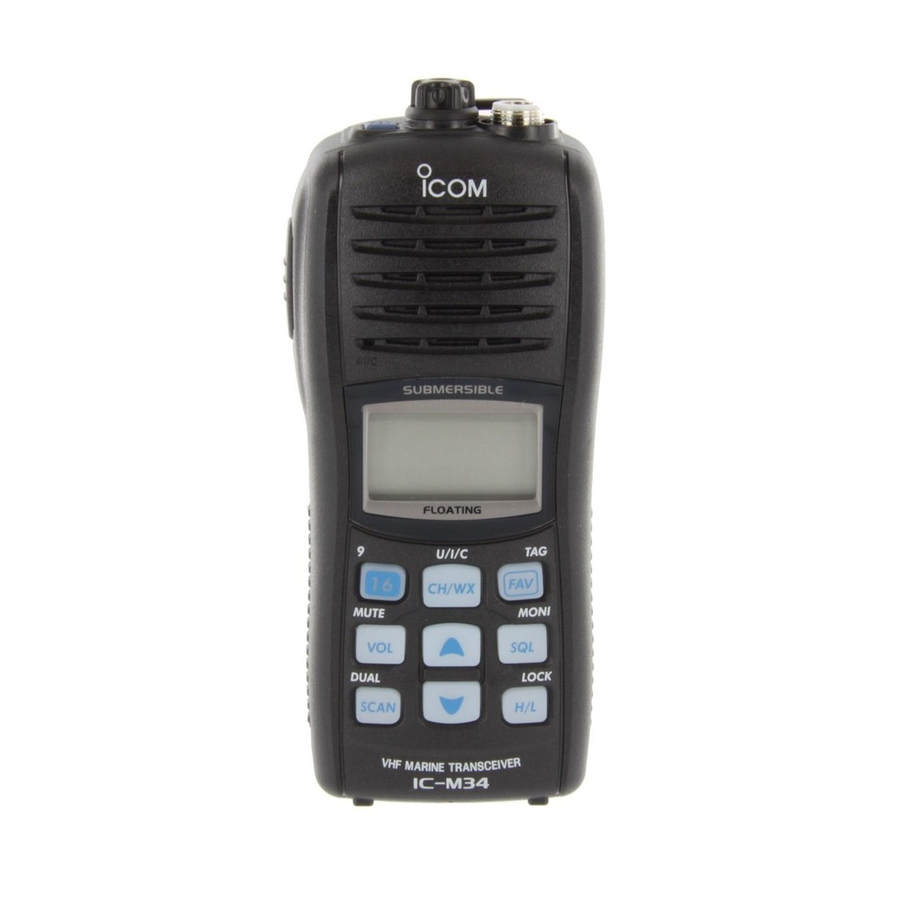
Page 10: Panel Description
PANEL DESCRIPTION ■ Front, top and side panels q POWER SWITCH [PWR] Push and hold to turn power ON and OFF. w SPEAKER-MICROPHONE CONNECTOR [SP MIC] (p. 25) Connects the optional external speaker-microphone. NOTE: Attach the [SP MIC] cap when the optional speaker-microphone is not used. - Page 11 PANEL DESCRIPTION t FAVORITE/TAG KEY [FAV•TAG] o SCAN/DUAL KEY [SCAN•DUAL] ➥ While pushing and holding this key, push [Y]/[Z] to ➥ Push to start or stop normal or priority scan. (p. 15) select the favorite (TAG) channels with ignoring un- ➥...
-
Page 12: Function Display
PANEL DESCRIPTION ■ Function display t LOCK INDICATOR (p. 12) Appears while the lock function is activated. y BATTERY INDICATOR Indicates remaining battery power. Indication Charging Battery level Full Middle No battery required blinks when the battery is over charged. blinks when the battery is exhausted. -
Page 13: Panel Description
PANEL DESCRIPTION !1 SQUELCH LEVEL INDICATOR !8 LOW POWER INDICATOR (p. 10) Shows the squelch level. ➥ “LOW” appears when low power is selected. ➥ “LOW” blinks when switching forced low power mode !2 VOLUME LEVEL INDICATOR because of a high temperature error or low voltage. -
Page 14: Basic Operation
BASIC OPERATION ■ Channel selection D Channel 9 (Call channel) IMPORTANT: Prior to using the transceiver for the first time, the battery pack must be fully charged for optimum Each regular channel group has separate leisure-use call life and operation. To avoid damage to the transceiver, channels. -
Page 15: Weather Channels
BASIC OPERATION D U.S.A., International and Canadian channels D Weather channels The transceiver is pre-programmed with 59 U.S.A., 59 Inter- The transceiver has 10 pre-programmed weather channels. national and 63 Canadian channels. These channel groups These are used for monitoring broadcasts from the NOAA may be specified for the operating area. -
Page 16: Receiving And Transmitting
BASIC OPERATION ■ Receiving and transmitting CAUTION: Transmitting without an antenna will damage IMPORTANT: To maximize the readability of your trans- mitted signal, pause a few sec. after pushing [PTT], hold the transceiver. the microphone 5 to 10 cm (2 to 4 inches) from your q Push and hold [PWR] to turn power ON. -
Page 17: Call Channel Programming
BASIC OPERATION ■ Call channel programming ■ Adjusting the volume level The volume level can be adjusted with [VOL] and [Y]/[Z]. Call channel is used to access Channel 9 (default), however, you can program the call channel with your most often-used channels in each channel group for quick recall. -
Page 18: Adjusting The Squelch Level
BASIC OPERATION ■ Adjusting the squelch level ■ Lock function To adjust the squelch level, use the [Y]/[Z] keys as de- This function electronically locks all keys (except for [PTT], scribed below. In order to receive signals properly, as well [SQL•MONI], [VOL•MUTE], [H/L•LOCK] and [Y]/[Z]*) to as for the scan to function effectively, the squelch must be prevent accidental channel changes and function access. -
Page 19: Monitor Function
BASIC OPERATION ■ Monitor function ■ AquaQuake water draining function The monitor function opens the squelch. See p. 5 for details of the monitor key action. The transceiver uses a new technology to clear water away ➥ The monitor function activates while pushing and holding from the speaker grill: AquaQuake. -
Page 20: Scan Operation
SCAN OPERATION ■ Scan types Set the TAG channels (scanned channels) before scanning. Scanning is an efficient way to locate signals quickly over a wide frequency range. The transceiver has priority scan and Clear any TAG channels which inconveniently stop scanning, such as digital communications. -
Page 21: Setting Tag Channels
SCAN OPERATION ■ Setting TAG channels ■ Starting a scan For more efficient scanning, set the desired channels as TAG Set the weather alert function, priority scan function, scan channels or clear the TAG setting from unwanted channels. resume timer and auto scan function in advance, using set Channels that are not tagged will be skipped during scan- mode. -
Page 22: Dualwatch/Tri-Watch
DUALWATCH/TRI-WATCH ■ Description ■ Operation Dualwatch monitors Channel 16 while you are receiving q Select Dualwatch or Tri-watch in set mode. (p. 19) on another channel; Tri-watch monitors Channel 16 and the w Select the desired channel. call channel while receiving another channel. Dualwatch/Tri- e Push and hold [DUAL] (SCAN) for 1 sec. -
Page 23: Set Mode
SET MODE ■ Set mode programming D Set mode operation Set mode is used to change the settings for 12 transceiver functions: Beep tone function, Weather alert function, Prior- q Turn power OFF. ity scan function, Scan resume timer, Auto scan function, w W hile pushing [SQL], turn power ON to enter set mode. -
Page 24: Set Mode Items
SET MODE ■ Set mode items D Priority scan function D Beep tone function “Pr” “bP” The transceiver has 2 scan types— normal (OFF) and prior- Select the key touch beep sound from ON or US, or turn sound OFF. ity (ON) scans. -
Page 25: Auto Scan Function
SET MODE D Auto scan function D Monitor key action “AS” “Sq” The auto scan function starts the desired scan automatically The monitor key opens the squelch temporarily. This key action when no signal is received, and no operation is performed contains PUSH (Pu) or HOLD (Ho) settings as shown below. -
Page 26: Set Mode
SET MODE D LCD contrast setting “LC” D Squelch sensitivity “SS” Set the LCD contrast level from High contrast or Low con- When this function is turned ON, rejection of noise is im- trast. proved so that the squelch is not easily affected by noise. NOTE: The LCD contrast level between High contrast and Low contrast makes no difference indoors. -
Page 27: Battery Charging
Icom radios or Icom charger. Only Icom battery seawater, or any other liquids. Do not charge or use a wet pack is tested and approved for use and charge with Icom battery. If the battery gets wet, be sure to wipe it dry before radios or Icom charger. -
Page 28: D Charging Caution
If any R DANGER! NEVER charge the battery pack in areas with of these conditions occur, contact your Icom dealer or dis- extremely high temperatures, such as near fires or stoves, tributor. -
Page 29: Supplied Battery Charger
Transceiver NOTE: The transceiver floats even the optional battery Charge indicator lights orange when case is attached. However, Icom recommends to use Turn power OFF the battery pack the following brand's alkaline batteries that we verified. (with/without If another brand's alkaline batteries are used, the transceiver) transceiver may sink. -
Page 30: Optional Battery Charger
BATTERY CHARGING ■ Optional battery charger D Charging D BC-162 installation q Connect the AC adapter as shown below. • To a desktop • To a wall w Insert the battery pack with/without the transceiver into Supplied screws Supplied screws the charger. -
Page 31: Optional Speaker-Microphone
OPTIONAL SPEAKER-MICROPHONE ■ HM-165 descriptions ■ Attachment Alligator type clip Turn power OFF before attaching the speaker-microphone. Then, insert the speaker-mic connector onto the [SP MIC] To attach the speaker-mic. to your shirt or collar, etc. connector and carefully screw it tight, as shown in the dia- gram below. -
Page 32: Troubleshooting
TROUBLESHOOTING PROBLEM POSSIBLE CAUSE SOLUTION REF. The transceiver does not turn • The battery is exhausted. • Recharge the battery pack. p. 23 • The battery pack is not attached cor- • Attach the battery pack correctly. p. 3 rectly. No sound from speaker. -
Page 33: Vhf Marine Channel List
VHF MARINE CHANNEL LIST Channel number Frequency (MHz) Channel number Frequency (MHz) Channel number Frequency (MHz) Channel number Frequency (MHz) CAN Transmit Receive CAN Transmit Receive CAN Transmit Receive CAN Transmit Receive 156.050 160.650 157.050 161.650 156.425 156.425 157.325 157.325 156.050 156.050 21A 157.050 157.050 156.475 156.475... -
Page 34: Specifications And Options
: 70 dB typical • Audio output power : 0.35 W typical at 10% distortion with an Icom optional equipment is designed for optimal performance when used with 8 Ω load this transceiver. We are not responsible for the transceiver being damaged or any accident caused when using non-Icom optional equipment. -
Page 35: Fcc Information
FCC INFORMATION FOR CLASS B UNINTENTIONAL RADIATORS This equipment has been tested and found to comply with the limits for a Class B digital device, pursuant to part 15 of the FCC Rules. These limits are designed to provide reasonable protection against harmful interference in a residential installation. - Page 36 A-6544H-1EX-w Printed in Japan 2006–2009 Icom Inc. © 1-1-32 Kamiminami, Hirano-ku, Osaka 547-0003, Japan Printed on recycled paper with soy ink.
Need help?
Do you have a question about the IC-M34 and is the answer not in the manual?
Questions and answers