
Subscribe to Our Youtube Channel
Related Manuals for Icom IC-M34


Summary of Contents for Icom IC-M34
-
Page 1: Instruction Manual
INSTRUCTION MANUAL VHF MARINE TRANSCEIVER iM34 This device complies with Part 15 of the FCC Rules. Operation is subject to the condition that this device does not cause harmful interference. -
Page 2: Safety Training Information
The radio is transmitting when the “TX indicator” lights red. You can cause the radio to transmit by the FCC RF exposure limits for “Occupational Use Only”. In addition, your Icom radio complies with the following Standards and Guidelines with regard to RF pressing the “PTT”... -
Page 3: In Case Of Emergency
IN CASE OF EMERGENCY RECOMMENDATION CLEAN THE TRANSCEIVER THOROUGHLY WITH FRESH If your vessel requires assistance, contact other vessels and WATER after exposure to saltwater, and dry it before opera- the Coast Guard by sending a distress call on Channel 16. tion. -
Page 4: Foreword
With dimensions of 16(H) 32(W) mm; ⁄ ⁄ EXPLICIT DEFINITIONS inch, the IC-M34’s function display is easy to read and shows operating conditions at a glance. Backlighting and WORD DEFINITION contrast can be adjusted to suit your preferences. Personal injury, fire hazard or electric shock... -
Page 5: Precautions
Changes or modifications to this device, not KEEP the transceiver out of the reach of children. expressly approved by Icom Inc., could void your authority to KEEP the transceiver at least 0.9 meters (3.0 ft) away from operate this device under FCC regulations. -
Page 6: Table Of Contents
TABLE OF CONTENTS SAFETY TRAINING INFORMATION ......... i SCAN OPERATION ........... 14–15 I Scan types ..............14 IN CASE OF EMERGENCY ............. ii I Setting TAG channels ........... 15 RECOMMENDATION ............... ii I Starting a scan .............. 15 FOREWORD ................iii IMPORTANT ................ -
Page 7: Operating Rules
(1) SHIP STATION LICENSE When your craft is equipped with a VHF FM transceiver, you NOTE: Even though the IC-M34 is capable of operation must have a current radio station license before using the on VHF marine channels 3, 21, 23, 61, 64, 81, 82 and 83, transceiver. -
Page 8: Supplied Accessories And Attachments
SUPPLIED ACCESSORIES AND ATTACHMENTS I Supplied accessories D Handstrap Handstrap Battery pack Battery charger AC adapter Pass the handstrap through (with 2 screws) (Depending the loop on the side of the on version) transceiver as illustrated at right. This facilitates carry- ing. -
Page 9: Supplied Accessories And Attachments
To attach the battery pack: When attaching or removing a battery pack, make sure the Insert the battery pack in the IC-M34 completely, then turn the rubber seal is set in the groove of the battery pack cor- screw clockwise one quarter turn. -
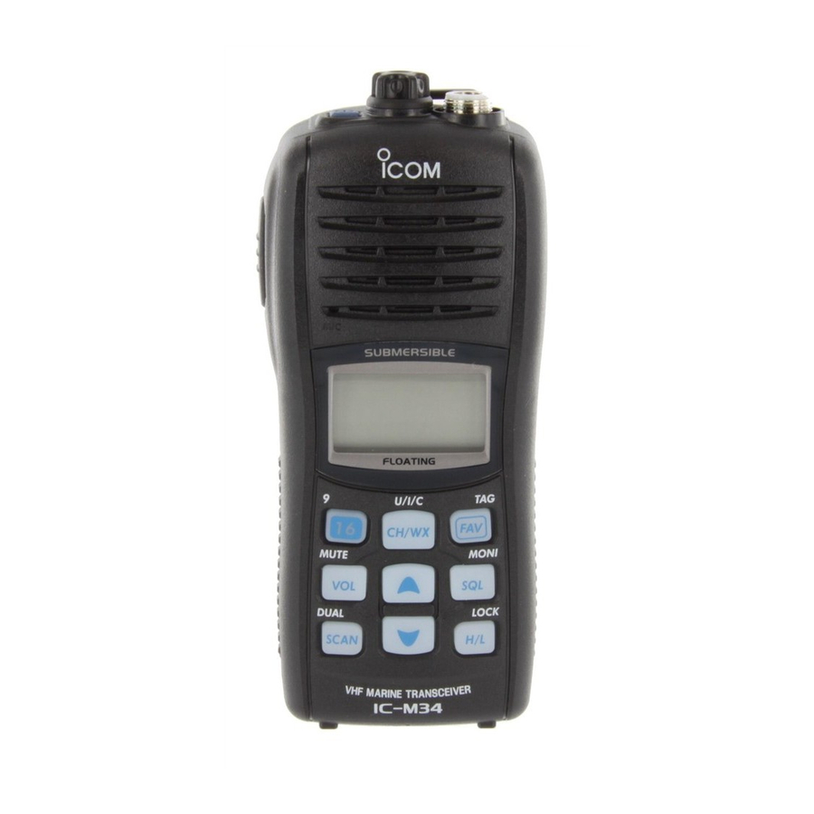
Page 10: Panel Description
PANEL DESCRIPTION I Front, top and side panels q POWER SWITCH [PWR] Push and hold to turn power ON and OFF. w SPEAKER-MICROPHONE CONNECTOR [SP MIC] (p. 25) Connects the optional external speaker-microphone. NOTE: Attach the [SP MIC] cap when the optional speaker-microphone is not used. - Page 11 PANEL DESCRIPTION t FAVORITE/TAG KEY [FAV•TAG] o SCAN/DUAL KEY [SCAN•DUAL] ➥ While pushing and holding this key, push [Y]/[Z] to se- ➥ Push to start or stop normal or priority scan. (p. 15) ➥ Push and hold for 1 sec. to enter watch mode. (p. 16) lect the favorite (TAG) channels with ignoring untagged ➥...
-
Page 12: I Function Display
PANEL DESCRIPTION I Function display t LOCK INDICATOR (p. 12) Appears while the lock function is activated. y BATTERY INDICATOR Indicates remaining battery power. Indication Charging Battery level Full Middle No battery required blinks when the battery is over charged. blinks when the battery is exhausted. -
Page 13: Panel Description
PANEL DESCRIPTION !1 SQUELCH LEVEL INDICATOR !8 LOW POWER INDICATOR (p. 10) ➥ “LOW” appears when low power is selected. Shows the squelch level. ➥ “LOW” blinks when switching forced low power mode !2 VOLUME LEVEL INDICATOR because of a high temperature error or low voltage. ➥... -
Page 14: Basic Operation
BASIC OPERATION I Channel selection D Channel 9 (Call channel) IMPORTANT!: Prior to using the transceiver for the first time, the battery pack must be fully charged for optimum Each regular channel group has separate leisure-use call life and operation. To avoid damage to the transceiver, turn channels. -
Page 15: Weather Channels
BASIC OPERATION D U.S.A., International and Canadian channels D Weather channels The IC-M34 is pre-programmed with 59 U.S.A., 59 Interna- The IC-M34 has 10 pre-programmed weather channels. tional and 63 Canadian channels. These channel groups may These are used for monitoring broadcasts from the NOAA be specified for the operating area. -
Page 16: I Receiving And Transmitting
For U.S.A version: To prevent accidental prolonged trans- e Push [Y Y ]/[Z Z ] to select the desired channel. mission, etc., the IC-M34 has a time-out timer function. • When receiving a signal, “ ” appears and audio is emitted This timer cuts a transmission OFF after 5 min. -
Page 17: I Call Channel Programming
BASIC OPERATION I Call channel programming I Adjusting the volume level The volume level can be adjusted with [VOL] and [Y Y ]/[Z Z ]. Call channel is used to access Channel 9 (default), however, you can program the call channel with your most often-used q Push [VOL], then adjust the volume level with [Y Y ]/[Z Z ]. -
Page 18: I Adjusting The Squelch Level
I Adjusting the squelch level I Lock function To adjust the IC-M34’s squelch level, use the [Y Y ]/[Z Z ] keys as This function electronically locks all keys (except for [PTT], [SQL•MONI], [VOL•MUTE], [H/L•LOCK] and [Y Y ]/[Z Z ]*) to described below. -
Page 19: I Monitor Function
Blinks while the monitor function is used. Push and hold I AquaQuake water draining function The IC-M34 uses a new technology to clear water away from the speaker grill: AquaQuake. AquaQuake helps drain water away from the speaker housing (water that might otherwise muffle the sound coming from the speaker). -
Page 20: Scan Operation
SCAN OPERATION I Scan types Scanning is an efficient way to locate signals quickly over a Set the TAG channels (scanned channels) before scanning. wide frequency range. The transceiver has priority scan and Clear any TAG channels which inconveniently stop scanning, normal scan. -
Page 21: I Setting Tag Channels
SCAN OPERATION I Setting TAG channels I Starting a scan For more efficient scanning, set the desired channels as TAG Set the weather alert function, priority scan function, scan re- channels or clear the TAG setting from unwanted channels. sume timer and auto scan function in advance, using set Channels that are not tagged will be skipped during scanning. -
Page 22: Dualwatch/Tri-Watch
DUALWATCH/TRI-WATCH I Description I Operation q Select Dualwatch or Tri-watch in set mode. (p. 19) Dualwatch monitors Channel 16 while you are receiving w Select the desired channel. on another channel; Tri-watch monitors Channel 16 and the e Push and hold [DUAL] (SCAN) for 1 sec. to start Dual- call channel while receiving another channel. -
Page 23: Set Mode
SET MODE I Set mode programming D Set mode operation Set mode is used to change the settings for 12 transceiver q Turn power OFF. functions: beep tone function, weather alert function, priority scan function, scan resume timer, auto scan function, dual/tri- w While pushing [SQL], turn power ON to enter set mode. -
Page 24: I Set Mode Items
SET MODE I Set mode items D Beep tone function D Priority scan function “bP” “Pr” Select the key touch beep sound from ON or US, or turn sound The transceiver has 2 scan types— normal (OFF) and priority OFF. (ON) scans. -
Page 25: Auto Scan Function
SET MODE D Auto scan function D Monitor key action “AS” “Sq” The auto scan function starts the desired scan automatically The monitor key opens the squelch temporarily. This key ac- when no signal is received, and no operation is performed for tion contains PUSH (Pu) or HOLD (Ho) settings as shown 30 sec. -
Page 26: Set Mode
SET MODE D LCD contrast setting D Squelch sensitivity “LC” “SS” Set the LCD contrast level from High contrast or Low con- When this function is turned ON, rejection of noise is im- trast. proved so that the squelch is not easily affected by noise. NOTE: The LCD contrast level between High contrast and Low contrast makes no difference indoors. -
Page 27: Battery Charging
Icom radios or Icom charger. Only Icom battery R DANGER! DO NOT expose the battery to rain, snow, sea- pack is tested and approved for use and charge with Icom ra- water, or any other liquids. Do not charge or use a wet bat- dios or Icom charger. - Page 28 If any R DANGER! NEVER charge the battery pack in areas with of these conditions occur, contact your Icom dealer or distrib- extremely high temperatures, such as near fires or stoves, in- utor.
-
Page 29: I Supplied Battery Charger
BATTERY CHARGING I Supplied battery charger I Optional battery case ï Charging connections When you would like to use the optional AAA(LR03) size bat- Do not charge batteries other than the BP-252. tery case (BP-251), install the batteries as illustrated below. q Attach the BC-173 to a flat surface, such as a desk, if desired. -
Page 30: I Optional Battery Charger
BATTERY CHARGING I Optional battery charger D BC-162 installation D Charging q Connect the AC adapter as shown below. • To a desktop • To a wall w Insert the battery pack with/without the transceiver into the Supplied screws Supplied screws charger. -
Page 31: Optional Speaker-Microphone
OPTIONAL SPEAKER-MICROPHONE I HM-165 descriptions I Attachment Turn power OFF before attaching the speaker-microphone. Alligator type clip Then, insert the speaker-mic connector onto the [SP MIC] To attach the speaker-mic. connector and carefully screw it tight, as shown in the dia- to your shirt or collar, etc. -
Page 32: Troubleshooting
TROUBLESHOOTING PROBLEM POSSIBLE CAUSE SOLUTION REF. The transceiver does • The battery is exhausted. • Recharge the battery pack. p. 23 not turn ON. • The battery pack is not attached correctly. • Attach the battery pack correctly. p. 3 No sound from speaker. -
Page 33: Vhf Marine Channel List
VHF MARINE CHANNEL LIST Channel number Frequency (MHz) Channel number Frequency (MHz) Channel number Frequency (MHz) Channel number Frequency (MHz) CAN Transmit Receive CAN Transmit Receive CAN Transmit Receive CAN Transmit Receive 156.050 160.650 157.050 161.650 156.425 156.425 157.325 157.325 156.050 156.050 21A 157.050 157.050 156.475 156.475... -
Page 34: Specifications
SPECIFICATIONS ï GENERAL ï RECEIVER • Frequency coverage : Transmit 156.025–157.425 MHz • Receive system : Double-conversion Receive 156.050–163.275 MHz superheterodyne • Mode : FM (16K0G3E) • Sensitivity (12 dB SINAD) : 0.25 µV typical • Channel spacing : 25 kHz •... -
Page 35: Options
OPTIONS D BATTERY CASE AND PACK • BP-251 BATTERY CASE Battery case for 5 AAA (LR03) alkaline cells. Output power level: 2 W • BP-252 i-Ion BATTERY PACK 7.4 V/980 mAh Li-Ion battery pack. D CHARGERS • BC-173 + BC-174A/E DESKTOP CHARGER AC ADAPTER Used for regular charging of battery pack. - Page 36 A-6544H-1EX Printed in Japan 2006 Icom Inc. © 1-1-32 Kamiminami, Hirano-ku, Osaka 547-0003, Japan Printed on recycled paper with soy ink.
Need help?
Do you have a question about the IC-M34 and is the answer not in the manual?
Questions and answers
Our radio is turned on, volume up, squelch low and we hear nothing. Please help to troubleshoot.