Hitachi C 12LSH Technical Data And Service Manual
Slide compound miter saw
Hide thumbs
Also See for C 12LSH:
- Handling instructions manual (104 pages) ,
- Technical data and service manual (92 pages) ,
- Safety instructions and instruction manual (136 pages)
Table of Contents
Advertisement
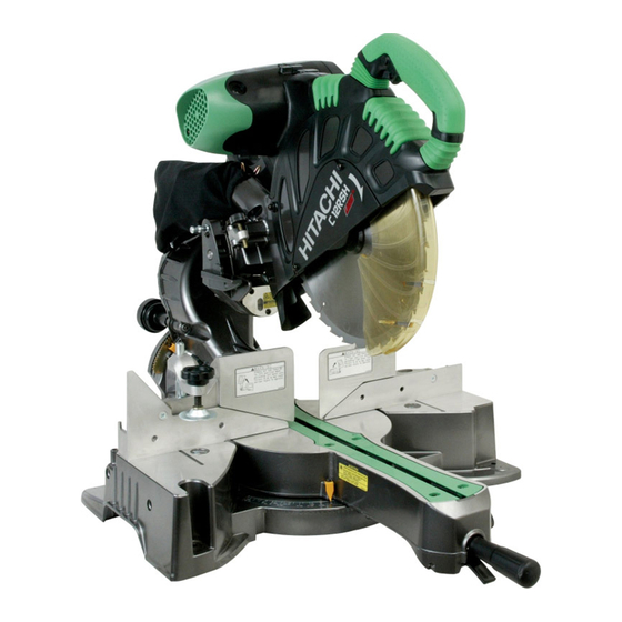
SLIDE COMPOUND MITER SAW
LIST Nos. C 12LSH: E941
C 12RSH: E942
Specifications AND PARTS ARE SUBJECT TO CHANGE FOR IMPROVEMENT
MODELS
Hitachi
Power Tools
C 12LSH
C 12RSH
Revised May 2007
C 12LSH
C 12RSH
TECHNICAL DATA
AND
SERVICE MANUAL
C
Advertisement
Table of Contents

Related Manuals for Hitachi C 12LSH


Summary of Contents for Hitachi C 12LSH
- Page 1 MODELS C 12LSH C 12RSH Hitachi Power Tools TECHNICAL DATA SLIDE COMPOUND MITER SAW C 12LSH SERVICE MANUAL C 12RSH LIST Nos. C 12LSH: E941 Revised May 2007 C 12RSH: E942 SPECIFICATIONS AND PARTS ARE SUBJECT TO CHANGE FOR IMPROVEMENT...
- Page 2 REMARK: Throughout this TECHNICAL DATA AND SERVICE MANUAL, a symbol(s) is(are) used in the place of company name(s) and model name(s) of our competitor(s). The symbol(s) utilized here is(are) as follows: Competitors Symbols Utilized Company Name Model Name LS1212 MAKITA DEWALT DW708...
-
Page 3: Table Of Contents
8-5. How to Use the Vise Assembly ....................25 8-6. Adjustment of Table Insert Position .................... 26 8-7. Cutting Operation ........................27 8-8. Digital Display Panel (Only Model C 12LSH) ................34 8-9. Precautions Concerning Electronic Condition ................35 9. ADJUSTMENT OF COMPONENTS ................... 36 9-1. -
Page 4: Table Of Contents
11-8. Lubrication ..........................66 11-9. Product Precision ........................66 11-10. Adjustment of Laser Marker Accuracy ..................67 12. REPAIR GUIDE ........................70 13. STANDARD REPAIR TIME (UNIT) SCHEDULES ..............76 Assembly Diagram for C 12LSH Assembly Diagram for C 12RSH... -
Page 5: Product Name
2. MARKETING OBJECTIVE The new slide compound miter saws Models C 12LSH and C 12RSH are introduced. They are compact thanks to the new sliding system that allows only the head portion to slide from the front to the back. They are equipped with the laser marker and the digital display panel that indicates miter/bevel angles (Model C 12LSH only) for increased visibility. -
Page 6: Selling Points
H50 mm x W260 mm (H1-15/16" x W10-3/16") Digital display panel that (15) Powerful 15 amps motor indicates miter/bevel angles (for the U.S.A. and Canada) (Only the Model C 12LSH) High dust collecting performance (6) Aggressive tool design (7) Conveniently positioned bevel (11) -
Page 7: Selling Point Descriptions
Therefore, the depth of the main unit remains unchanged (930 mm). The Models C 12LSH and C 12RSH are operable even in tight places such as a place where there is a wall behind. - Page 8 Fig. 2-a Fig. 2-b (2) Digital display panel that indicates miter/bevel angles (Only the Model C 12LSH) Use the digital display panel when cutting a workpiece at an optional angle. The digital display panel indicates a miter/bevel cutting angle with a numeric value. There is no reading error caused by visual check between the indicator and the scale.
- Page 9 (5) High sub fence The Models C 12LSH and C 12RSH have a high sub fence (right and left). Use the high sub fence for miter cutting, left and right bevel cutting or crown molding cutting. The high sub fence supports the workpiece widely for stable cutting.
- Page 10 Fig. 6 locking. (8) High dust collecting performance The dust collecting performance of the Models C 12LSH and C 12RSH are remarkably higher than the other models thanks to the adoption of new dust guide and gear case. Table 3...
- Page 11 (9) Positive angle stoppers The Models C 12LSH and C 12RSH have positive angle stoppers in the turn table at the right and the left of the 0û center setting, at 15û, 22.5û, 31.6û and 45û settings. Thanks to the positive angle stoppers, positioning can be done more securely than the ball index method utilized in the current Model C 12FSA.
- Page 12 24 mm (15/16")] 25 mm (1") Right 57û (Hitachi 107 x 170 107 x 180 98 x 155 C 12LSH, C 12RSH) (4-3/16" x 6-11/16") (4-3/16" x 7-1/16") (3-7/8" x 6-1/8") Right and left 57û 120 x 130 120 x 140...
- Page 13 Refer to "5. SPECIFICATIONS" as the capacities are different depending on the destinations. Maximum cutting dimension Table 7 Unit: mm (inch) Maker HITACHI Model HITACHI C 12LSH Max. C 12FSA cutting C 12RSH dimensions 70 x 312 Left 45û 55 x 310...
- Page 14 By turning the turn table to the left or right and inclining the saw blade section (head) to the left or right, the Models C 12LSH and C 12RSH are capable of compound cutting (bevel + miter, see Figs. 17, 18 and 19) of workpieces with the maximum dimensions shown in Table 8.
- Page 15 Fig. 17 Fig. 18 Fig. 19 (15) Powerful 15 amps motor (for the U.S.A. and Canada) The Models C 12LSH and C 12RSH are equipped with a 15-ampere motor. --- 11 ---...
-
Page 16: Specifications
5. SPECIFICATIONS Except for Europe 107 mm x 312 mm (4-3/16" x 12-1/4") 0û (Right angle) 120 mm x 260 mm (4-11/16" x 10-3/16") [with aux. board 25 mm (1")] 107 mm x 220 mm (4-3/16" x 8-5/8") Miter left/right 45û 120 mm x 180 mm (4-11/16"... - Page 17 Main unit dimensions 595 mm x 930 mm x 710 mm (23-7/16" x 36-5/8" x 27-15/16") (Width x Depth x Height) Weight C 12LSH 30 kg (66.1 lbs.) C 12RSH 29 kg (63.9 lbs.) Coating Gunmetallic silver Packaging Corrugated cardboard box...
-
Page 18: Comparisons With Similar Products
Not provided Laser marker Laser output <1 mW Digital display Provided (C 12LSH only) None None None * These numeric values are for the models destined for the U.S.A. and Canada. Refer to "5. SPECIFICATIONS" as the capacities are different depending on the destinations. - Page 19 (23-7/16" x 35-13/16" x (22-7/8" x 44-3/32" x mm (inch) 27-15/16") 27-1/4") 26") 29-9/16") C 12LSH 30 (66.1) Product weight kg (lbs.) 22 (48.4) 25.8 (57) 25 (55.1) C 12RSH 29 (63.9) • 305 mm (12") TCT • 305 mm (12") TCT •...
-
Page 20: Precautions In Sales Promotion
7. PRECAUTIONS IN SALES PROMOTION In the interest of promoting the safest and most efficient use of the Models C 12LSH and C 12RSH Slide Compound Miter Saws by all of our customers, it is very important that at the time of sale the salesperson... - Page 21 (2) Caution label (B) (at the front of holder (A)) Fig. 21 (3) Warning sign (at the front of sub fence (A) and sub fence (B)) Fig. 22 Fig. 23 (4) Caution Label (J) (at the front of the hinge) and Caution Label (C) (at the front left side of the turn table) Do not stare into laser beam.
-
Page 22: Relative Standards
(2) Laser radiation when open. DO NOT STARE INTO BEAM OR VIEW DIRECTLY WITH OPTICAL INSTRUMENTS. The life span of the laser marker in the Models C 12LSH and C 12RSH is about 3,600 hours. (About 3 years: 5 hours of use/day x 240 days/year) -
Page 23: Ambient Illuminance And Visibility Of Laser Line
Hitachi power tools dealer or Hitachi power tools center for servicing. (1) Be sure to use the carbon brushes dedicated to the Models C 12LSH and C 12RSH (110 V --- 120 V: Code No. 999038, 220 V--- 240 V: Code No. 999065). Use of other carbon brushes will adversely affect the brake performance. -
Page 24: Adjustment And Operational Precautions
8. ADJUSTMENT AND OPERATIONAL PRECAUTIONS 8-1. Confirmation of Saw Blade Lower Limit Position The lower limit of the saw blade cutting depth is factory-adjusted so that when the saw blade is fully lowered, its cutting edge is 9 to 11 mm (23/64" to 7/16") below the upper surface of the turn table in order to cut workpieces completely without cutting the bottom of the turn table groove. -
Page 25: Confirmation For Use Of Sub Fence (A) And Sub Fence (B)
8-2. Confirmation for Use of Sub Fence (A) and Sub Fence (B) The Models C 12LSH and C 12RSH are equipped with sub fence (A) and sub fence (B). Use sub fence (A) and sub fence (B) for miter cutting, left and right bevel cutting. -
Page 26: How To Use Guard
* For USA/CAN, the Models C 12LSH and C 12RSH are equipped with a fixed guard. CAUTION: As the guard may be damaged or broken if the groove is cut too quickly, the customer should be advised to perform this operation slowly and smoothly. -
Page 27: Position Adjustment Of Laser Line
8-4. Position Adjustment of Laser Line The laser line is adjusted to the width of the saw blade at the time of factory shipment. Depending upon the cutting choice, align the laser line with the left side of the cutting width (saw blade) or the right side according to the following procedure. - Page 28 CAUTION: Laser radiation - Do not stare into beam. Laser radiation on work table. Do not stare into beam. If your eye is exposed directly to the laser beam, it can be hurt. Do not dismantle it. Do not give strong impact to the laser marker (main body of tool); otherwise, the position of a laser line can go out of order, resulting in the damage of the laser marker as well as a shortened service life.
-
Page 29: How To Use The Vise Assembly
8-5. How to Use the Vise Assembly (1) The vise assembly can be mounted on either the left fence (fence (B)) or the right fence (fence (A)), and can be raised or lowered according to the height of the workpiece. To raise or lower the vise assembly, first loosen 6 mm wing bolt (A). -
Page 30: Adjustment Of Table Insert Position
8-6. Adjustment of Table Insert Position Table inserts are installed on the turn table. When the machine is shipped from the factory, the table inserts are positioned so that there is no chance that the saw blade will come in contact with either side of the saw blade slot even if the machine is used for 45û... -
Page 31: Cutting Operation
(3) Press cutting ( in Fig. 36) The Models C 12LSH/C 12RSH can be used for press cutting of workpieces up to 107 mm (4-3/16") square in a single operation by simply pushing the saw blade section downward in the same manner as the Model C 12FSA. - Page 32 Instruct the customer to always slide the saw blade section toward the fence while cutting, as shown by arrow in Fig. 36. On completion of the cutting operation, turn the switch off and wait for the saw blade to come to a complete stop before raising the handle to its original position.
- Page 33 Fig. 37 not caused by the performance of the saw blade or the Models C 12LSH/C 12RSH. In the cutting examples illustrated in Fig. 37, the cut surfaces on the sides marked (cut with the grain) are...
- Page 34 For miter cut setting If the turn table has been set to either of the angles described, move the turn table adjusting side handle a little to the right and left to stabilize the position and to properly align the miter scale and the tip of the indicator before the operation starts.
- Page 35 Fig. 40 Fig. 41 Fig. 43 Fig. 42 (3) Setting to cut crown moldings at positions in Fig. 39 (See Fig. 44, tilt the head to the right.): Turn the turn table to the right and set the miter angle as follows: For 45û...
- Page 36 Fig. 45 Fig. 44 Fig. 46 Fig. 47 Cutting method of crown molding without tilting the saw blade (1) Crown molding stoppers (L) and (R) (optional Crown molding vise ass'y Crown molding stopper (R) (optional accessory) (optional accessory) accessories) allow easier cuts of crown molding without 6 mm knob bolt 6 mm knob bolt...
- Page 37 To ensure that the tip of the 6 mm wing bolt is properly aligned with the desired locking groove on the vise shaft, simply align the upper surface of the fence to either of three v-grooves on the vise shaft surface or to the lower surface of the screw holder.
-
Page 38: Digital Display Panel (Only Model C 12Lsh)
8-8. Digital Display Panel (Only Model C 12LSH) Fig. 49 Fig. 50-a Fig. 50-b (1) Turning on the digital display switch shows 0û for both miter and bevel angle, regardless of main unit angle. (2) Align the main unit angle with the tilt angle (0û) and miter angle (0û) and hold down their reset buttons for at least 0.2 seconds. -
Page 39: Precautions Concerning Electronic Condition
The laser marker will not light up if the digital display switch is turned off. (Only Model C 12LSH) Do not use the main unit near equipment that generates electrical noise such as generators. -
Page 40: Adjustment Of Components
9. ADJUSTMENT OF COMPONENTS 9-1. Bevel Angle Adjustment Before the power tool is shipping from the factory, the height of 8 mm bolt (A), 8 mm bolt (B) and 8 mm set screw is adjusted so that the saw blade section (head) will stop at 0û (right angle), 45û to the left, and 45û to the right. To change the head stop positions, instruct the customer to adjust the height of 8 mm bolt (A), 8 mm bolt (B) and 8 mm set screw by turning them. -
Page 41: Packing
(2) Lubrication If it is necessary to replace the ball bushing, apply approximately 2 grams (0.1 oz) of grease (Nippeco SEP 3A) on the steel balls and within the guide grooves of the new ball bushing. If grease is not applied, it will shorten the service life of the ball bushing, and subsequent abrasive contact between the steel balls and slide pipe (B) will cause abnormal noise during slide cutting operations. - Page 42 (3) How to install packings (E) and (F) Put the main body mounted with packing (B) and packing (D) in the carton box aligning with the base packing. Cover the support at the rear of the main unit, housing and switch handle with two poly sheets. Insert packing (F) into the clearance near the switch handle at the front of the main unit and packing (E) into the clearance near the support at the rear of the main unit from above.
-
Page 43: Precautions In Disassembly And Reassembly
[Bold] numbers in the descriptions below correspond to the item numbers in the parts list and exploded assembly diagram of the Model C 12LSH. For the Model C 12RSH, refer to the parts list separately. * Be sure to first disconnect the power plug when performing disassembly or replacement of the saw blade. - Page 44 Item Disassembly Disassembly procedure Necessary tools spots Turn table, base ass'y Fig. 58 --- 40 ---...
- Page 45 Item Disassembly Disassembly procedure Necessary tools spots (1) Remove the Knob Bolt [335] or the Tapping Screw (W/Flange) Turn table, base ass'y D5 x 25 (Black) [172], Guard [336] and Guard Holder [337] or the Guard Ass'y [176] from Holder (A) [145]. (2) Remove the two Flat Hd.
- Page 46 Item Disassembly Disassembly procedure Necessary tools spots Turn table, base NOTE: Do not lose Spring (C) [15A] as Spring (C) [15A] pops out ass'y when removing the Encoder [16A]. When reinstalling the Encoder [16A] to the Turn Table [26], move the Encoder [16A] away from Gear (A) [8] and secure it at this position with the Machine Screw M5 x 20 [13] temporarily.
- Page 47 Item Disassembly Disassembly procedure Necessary tools spots Turn table, base (23) Remove the Machine Screw M4 x 8 [34] and remove Spring (E) ass'y [27], Stopper (A) [28] and Pin Cover [32] from the Turn Table [26]. (24) Remove the Machine Screw M4 x 8 [34] and pull out the Lever Shaft [85] to remove the Lever [89], Spring (D) [90] and Shaft (C) [88] from the Turn Table [26].
- Page 48 Disassembly Item Disassembly procedure Necessary tools spots Protective cover, link 291A 285B Fig. 59 (1) Remove the two Machine Screws (W/Washers) M5 x 12 (Black) [264] and remove the Spindle Cover [265] from the Gear Case Phillips screwdriver [275]. (2) Remove Bolt (A) M10 [284] with the Box Wrench 17 mm [501]. Remove the Washer (B) [285B] or Washer (D) [348], TCT Saw 17-mm box wrench...
- Page 49 Disassembly Item Disassembly procedure Necessary tools spots Gear case, spring, support, hinge (A), ball bushing, holder 156A Fig. 60 --- 45 ---...
- Page 50 Item Disassembly Disassembly procedure Necessary tools spots Phillips (1) Remove the Machine Screw M4 x 12 [276] and remove the Nylon Gear case, screwdriver spring, support, Clip [278] from the Gear Case [275] (head). hinge (A), ball 4-mm hex. bar (2) Remove the Seal Lock Hex.
- Page 51 Item Disassembly Disassembly procedure Necessary tools spots Phillips (8) Remove the Machine Screw M4 x 8 [141]. Lightly tap the end Gear case, screwdriver spring, support, surface of Hinge (A) [173] with a plastic hammer to remove the hinge (A), ball Ball Bushing [144].
- Page 52 Disassembly Item Disassembly procedure Necessary tools spots Belt, pinion ass'y, spindle ass'y 312A Fig. 61 Phillips (1) Remove the four Machine Screws (W/Washers) M5 x 25 (Black) screwdriver [242] and remove the Pulley Cover [317] from the Gear Case [275]. (2) Pull the Belt (200H10) 16 x 508 [310] outward and turn it to remove from Pulley (A) [307] and Pulley (B) [305].
- Page 53 Disassembly Item Disassembly procedure Necessary tools spots Monitor, stator ass'y, armature ass'y, pulley (A), switch, laser marker 256A 198A Fig. 62 Phillips (1) Remove the two Tapping Screws (W/Flange) D4 x 16 (Black) [344] screwdriver to remove the Lever Cover [343]. (2) Remove the two Tapping Screws (W/Flange) D4 x 16 [341] and the Machine Screw (W/Washers) M4 x 16 [342] to remove the Lever [339] and the Lever Spring [345].
- Page 54 Item Disassembly Disassembly procedure Necessary tools spots Nippers (6) Cut the internal wires at the root of the three Connectors 50092 Monitor, stator ass'y, armature [267] that crimp the internal wire coming from the Stator Ass'y [253] ass'y, pulley (A), and the internal wire at the root of one Connector 50092 [267] that switch, laser crimps the Cord [235] and Internal Wire (A) [266].
- Page 55 Item Disassembly Disassembly procedure Necessary tools spots Monitor, stator (15) Removal of the Switch (3P Faston Type) W/O Lock [268]: ass'y, armature (a) Remove Switch Handle (R) [269] and Switch Handle (L) [263] from ass'y, pulley (A), the Gear Case [275] according to the procedure of Item No. 5-(3). switch Then the Switch (3P Faston Type) W/O Lock [268] can be removed.
- Page 56 Disassembly Item Disassembly procedure Necessary tools spots Vise ass'y Phillips (1) Remove the Wing Bolt M6 x 12 [38] to screwdriver remove the Vise Shaft [44]. (2) Remove the Machine Screw (W/Washers) M5 x 12 (Black) [43] to remove the Vise Plate [42] and the Washers [41].
-
Page 57: Reassembly
11-3. Reassembly Reassembly can be accomplished by following the disassembly procedures in reverse. However, special attention should be given to the following items. (1) Prior to reassembly, measure the insulation resistance of the armature, stator, switch and Back of the turn table other electrical components and confirm that the insulation resistance of each part is more than 5 M Ω. -
Page 58: Wiring Diagram
WARNING: Be sure to turn off the two switches (w/cover) on the top of the Monitor [260] (Model C 12LSH), or turn off the switch (w/cover) on the side of Handle (R) [238] (Model C 12RSH) and unplug the power cord plug from the receptacle before replacing the Laser Marker [198A] and the Switching Power Supply [233]. - Page 59 C 12LSH Fig. 67-2 --- 55 ---...
- Page 60 Europe/AUS/Asia C 12LSH Fig. 67-3 --- 56 ---...
- Page 61 C 12RSH USA/CAN Fig. 68-1 --- 57 ---...
- Page 62 C 12RSH Fig. 68-2 Europe/AUS/Asia C 12RSH Fig. 68-3 --- 58 ---...
- Page 63 2 Actual wiring diagram USA/CAN C 12LSH Fig. 69-1 --- 59 ---...
- Page 64 C 12LSH Fig. 69-2 --- 60 ---...
- Page 65 C 12LSH Europe/AUS/Asia Fig. 69-3 --- 61 ---...
- Page 66 USA/CAN C 12RSH Fig. 70-1 --- 62 ---...
- Page 67 C 12RSH Fig. 70-2 --- 63 ---...
- Page 68 Europe/AUS/Asia C 12RSH Fig. 70-3 --- 64 ---...
-
Page 69: Checking Of Insulation Distance
11-5. Checking of Insulation Distance Do not remove too much of the insulation coating at the internal wire connection. Take care not to let the core of the internal wire stick out the Connector 50092 [267] or let the internal wires get caught in a joint between Switch Handle (R) [269] and Switch Handle (L) [263]. -
Page 70: Lubrication
(3) Reassembly of the ball bushing The Ball Bushing [144], Holder (A) [145] and Hinge (A) [173] are maintained at a smooth fit. When placing the Ball Bushing [144] into Holder (A) [145] and Hinge (A) [173] gently hammer it with a plastic hammer so that the Ball Bushing [144] is seated into Holder (A) [145] and Hinge (A) [173] in parallel. -
Page 71: Adjustment Of Laser Marker Accuracy
11-10. Adjustment of Laser Marker Accuracy (1) Construction of laser marker and functions of each component The Adjuster [191] located at the side of Hinge (A) [173] is a screw used for moving the Laser Marker [198A] horizontally. The laser line can be aligned with the left side of the cutting width (saw blade) or the ink line on the right side by means of the Adjuster [191]. - Page 72 Adjustment of squareness with the fence surface Adjustment of squareness with the base surface [198A] [198A] Fig. 75-b Fig. 75-c The laser line inclines to the right by turning the Seal The laser line inclines to the left by turning the Seal Lock Hex.
- Page 73 Next, insert a 2.5-mm hex. bar wrench into the inlet and adjust the two Seal Lock Hex. Socket Set Screws M5 x 6 [200] so that laser beam is applied to the entire cutting surface. (Before adjustment of the Laser Marker [198A] using a 2.5-mm hex.
-
Page 74: Repair Guide
12. REPAIR GUIDE Factory Item Phenomenon Cause (s) Inspection, repair or adjustment standard a Inaccurate 0.15/100 • Readjust squareness with the Inaccurate cutting squareness between (Dummy disc) Nylock Hex. Socket Set Inaccurate • • • the turn table and the (Fig. - Page 75 Factory Item Phenomenon Inspection, repair or adjustment Cause (s) standard • Adjust the clearance between Holder (A) the Bushing [143] and Slide Slide pipe (A) Pipe (A) [149] with the Seal Lock Hex. Socket Set Screw M6 x 10 [148]. Ensure that slide pipe section slides smoothly with a slide load of within 3 kgf.
- Page 76 Factory Item Phenomenon Inspection, repair or adjustment Cause (s) standard a Large deflection of • Same as Item 1- b . Rough cut surface 0.2/ φ 295 saw blade. Parallelism = 0.02/54 (Dummy disc) (Causes rough cut surface.) Slide load should b Poor movement of •...
- Page 77 Factory Item Phenomenon Inspection, repair or adjustment Cause (s) standard a Excessively fast • Reduce cutting speed. Saw blade is locked. ------ cutting speed b Core diameter of ------ • Use a thicker and shorter extension cord is too extension cord. small.
- Page 78 Switch failure • Check the laser switch ------ (w/cover) on the top of the Monitor [260] for conductivity. (Model C 12LSH) • Replace the Monitor [260]. (Model C 12LSH) • Check the Switch (W/Cover) [319] on the side of Handle (R) [238] for conductivity.
- Page 79 Digital display does a Improper wiring in the • Check the wiring. not indicate anything. monitor, break in the • Replace the Monitor [260]. (Only Model C 12LSH) internal wiring, monitor failure, or controller failure ------ b Switching power • Check the Switching Power...
-
Page 80: Standard Repair Time (Unit) Schedules
13. STANDARD REPAIR TIME (UNIT) SCHEDULES Variable MODEL 60 min. Fixed Work Flow C 12RSH C 12LSH Switch Handle (L) Switch Switch Handle (R) Link Ball Bearing Spindle Ass'y (6003DD) Ball Bearing (606ZZ) Bearing Holder Cover Ball Bearing (608VV) Safety Cover (B) - Page 81 Hitachi Power Tools LIST NO. E941 ELECTRIC TOOL PARTS LIST SLIDE COMPOUND MITER SAW 2007 • • Model C 12LSH (E2) 606 616 617 618 605 626...
- Page 82 C 12LSH 156A 198A 187A --- 2 --- 5 -- 07...
- Page 83 C 12LSH 256A 312A 291A 502A 285B 5 -- 07 --- 3 -- -...
- Page 84 PARTS C 12LSH ITEM CODE NO. DESCRIPTION REMARKS USED 949-217 MACHINE SCREW M4X12 (10 PCS.) 949-429 BOLT WASHER M4 (10 PCS.) 324-371 COVER (B) 987-512 MACHINE SCREW (W/SP. WASHER) M5X16 324-390 SUPPORT (E) 324-391 HOLDER SHAFT 305-592 NEEDLE D5X19.8 323-604...
- Page 85 PARTS C 12LSH ITEM CODE NO. REMARKS DESCRIPTION USED 949-342 FLAT HD. SCREW M6X25 (10 PCS.) 998-834 HOLDER 949-610 BOLT M6X10 (10 PCS.) 323-604 GEAR (A) 323-603 PACKING (A) 323-606 BASE RUBBER 324-393 BASE ASS’Y INCLUD. 52, 56-58, 99 302-317...
- Page 86 PARTS C 12LSH ITEM CODE NO. DESCRIPTION REMARKS USED 949-217 MACHINE SCREW M4X12 (10 PCS.) 949-429 BOLT WASHER M4 (10 PCS.) 324-389 COVER (D) 307-294 MACHINE SCREW (W/WASHERS) M5X16 (BLACK) 324-383 SIDE COVER 949-215 MACHINE SCREW M4X8 (10 PCS.) 949-429 BOLT WASHER M4 (10 PCS.)
- Page 87 PARTS C 12LSH ITEM CODE NO. REMARKS DESCRIPTION USED 324-376 LINK 328-522 LINK FOR EUROPE 319-270 ADJUSTER 973-313 NYLON CLIP 305-180 CLUTCH SCREW 305-179 CLUTCH SPRING 962-614 ADJUSTING WASHER (B) T0.5 319-268 PLATE (B) 305-179 CLUTCH SPRING 198A 321-348 LASER MARKER...
- Page 88 PARTS C 12LSH ITEM CODE NO. DESCRIPTION REMARKS USED 937-623 BRUSH TERMINAL 340-626D STATOR ASS’Y 110V INCLUD. 252 340-626C STATOR ASS’Y 120V INCLUD. 252 340-703E STATOR (B) ASS’Y 220V-230V INCLUD. 252 340-693E STATOR ASS’Y (C) 230V INCLUD. 252 FOR NZL 340-703F STATOR (B) ASS’Y 240V...
- Page 89 PARTS C 12LSH ITEM CODE NO. REMARKS DESCRIPTION USED 291A 328-188 RETURN SPRING (B) 324-438 SPINDLE ASS’Y INCLUD. 293-295 600-3DD BALL BEARING 6003DDCMPS2S 324-439 BEARING HOLDER 608-VVM BALL BEARING 608VVC2PS2L 949-241 MACHINE SCREW M5X20 (10 PCS.) 949-454 SPRING WASHER M5 (10 PCS.)
- Page 90 STANDARD ACCESSORIES C 12LSH ITEM CODE NO. DESCRIPTION REMARKS USED 985-051 BOX WRENCH 17MM 502A 322-955 DUST BAG (BLACK) OPTIONAL ACCESSORIES ITEM CODE NO. DESCRIPTION REMARKS USED 960-017 KNOB BOLT M6X32 321-390 CROWN MOLDING STOPPER HOLDER CROWN MOLDING STOPPER (L)
- Page 91 Hitachi Power Tools LIST NO. E942 ELECTRIC TOOL PARTS LIST SLIDE COMPOUND MITER SAW 2007 • • Model C 12RSH (E2) 606 616 617 618 605 626...
- Page 92 C 12RSH 156A 198A 187A --- 2 --- 5 -- 07...
- Page 93 C 12RSH 256A 312A 291A 502A 285B 5 -- 07 --- 3 -- -...
- Page 94 PARTS C 12RSH ITEM CODE NO. DESCRIPTION REMARKS USED 324-391 HOLDER SHAFT 324-612 NYLOCK HEX. SOCKET SET SCREW M8X16 324-399 GEAR (A) 949-325 FLAT HD. SCREW M4X16 (10 PCS.) 324-416 SCALE (B) 303-409 NYLOCK BOLT M8X25 324-401 SHAFT (B) 955-818 BOLT WASHER M16 324-402 SPRING (B)
- Page 95 PARTS C 12RSH ITEM CODE NO. REMARKS DESCRIPTION USED 949-432 BOLT WASHER M6 (10 PCS.) 949-556 NUT M6 (10 PCS.) 324-409 KNOB (A) 950-817 METAL D8X10 324-406 BEVEL GEAR 949-454 SPRING WASHER M5 (10 PCS.) 949-241 MACHINE SCREW M5X20 (10 PCS.) 321-339 LEVER SHAFT CAUTION LABEL (C)
- Page 96 PARTS C 12RSH ITEM CODE NO. DESCRIPTION REMARKS USED 321-329 INDICATOR CAUTION LABEL (B) 324-466 SLIDE PIPE (B) 305-558 1 FOR USA, CAN TAPPING SCREW (W/FLANGE) D5X25 (BLACK) 324-467 HINGE (A) 324-421 GRIP 307-294 MACHINE SCREW (W/WASHERS) M5X16 (BLACK) 324-372 GUARD ASS’Y 1 INCLUD.
- Page 97 PARTS C 12RSH ITEM CODE NO. REMARKS DESCRIPTION USED 500-474Z CORD 1 (CORD ARMOR D10.1) FOR TPE 500-423Z CORD 1 (CORD ARMOR D10.1) FOR SIN, UAE, MAL 500-468Z CORD 1 (CORD ARMOR D10.1) FOR THA, PHI 319-349 CORD BUSH 324-461 HANDLE (R) 938-051 CORD ARMOR D10.1...
- Page 98 PARTS C 12RSH ITEM CODE NO. DESCRIPTION REMARKS USED 949-429 BOLT WASHER M4 (10 PCS.) 973-313 NYLON CLIP 949-260 MACHINE SCREW M6X25 (10 PCS.) 606-ZZM BALL BEARING 606ZZC2PS2L 949-455 SPRING WASHER M6 (10 PCS.) 949-425 WASHER M6 (10 PCS.) 935-196 MACHINE SCREW (W/WASHERS) M4X12 (BLACK) 988-101 BOLT (A) M10...
- Page 99 PARTS C 12RSH ITEM CODE NO. REMARKS DESCRIPTION USED * 336 326-828 GUARD 1 EXCEPT FOR USA, CAN * 337 321-394 GUARD HOLDER 1 EXCEPT FOR USA, CAN * 338 328-521 SUB COVER 1 FOR EUROPE, AUS, NZL * 339 328-518 LEVER 1 FOR EUROPE, AUS, NZL...
- Page 100 STANDARD ACCESSORIES C 12RSH ITEM CODE NO. DESCRIPTION REMARKS USED 985-051 BOX WRENCH 17MM 502A 322-955 DUST BAG (BLACK) OPTIONAL ACCESSORIES ITEM CODE NO. DESCRIPTION REMARKS USED 960-017 KNOB BOLT M6X32 321-390 CROWN MOLDING STOPPER HOLDER CROWN MOLDING STOPPER (L) 301-806 WING BOLT M6X15 321-374...
Need help?
Do you have a question about the C 12LSH and is the answer not in the manual?
Questions and answers