Advertisement
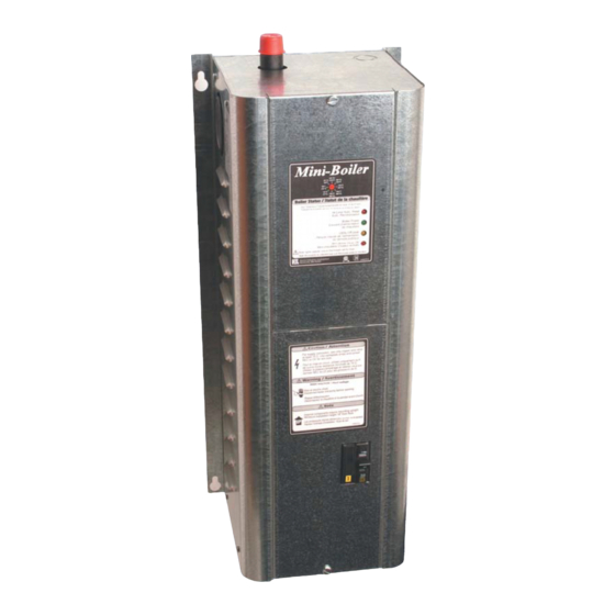
Mini-Boiler
Installation & Operating
Model EMB-5
Model EMB-9
Application - Low temperature, low pressure, radiant underfloor heating systems.
Comment - If this application is for traditional hydronics heating requiring temperatures greater
than 140° F (60° C) and capacities larger than shown above, contact factory for other Electro-
Boiler product series.
Accessories – Attached BL001 lists various accessory or option items which are not part of basic
Electro-Boiler. Page 1 gives information on a zone control update which stages elements based
upon zone capacity.
Note:
This product meets the requirements of the ASME Boiler and Pressure
Vessel Code.
Drawings:
BX301
BH302
BS302
BL001
08/07/2008
Electric
Instructions
4.5 kW
3 GPM (11.35 L/min) minimum flow
9 kW
4 GPM (15.14 L/min) minimum flow
TM
BI301D
Advertisement
Table of Contents

Related Manuals for Electro Industries Mini-Boiler EMB-5


Summary of Contents for Electro Industries Mini-Boiler EMB-5
- Page 1 Electric Mini-Boiler Installation & Operating Instructions Model EMB-5 4.5 kW 3 GPM (11.35 L/min) minimum flow Model EMB-9 9 kW 4 GPM (15.14 L/min) minimum flow Application - Low temperature, low pressure, radiant underfloor heating systems. Comment - If this application is for traditional hydronics heating requiring temperatures greater than 140°...
-
Page 2: Table Of Contents
TABLE OF CONTENTS Description Page System Components System or Water Flow Room Thermostat Placement Built in Temperature Control Water Flow Calculation Installation Requirements Mechanical Installation Water Fill Procedure Electrical Hook-up Slab Stat Zone Controller Operational Tips Drawings: Piping, install kit BX301 Hook-up BH302... -
Page 3: System Or Water Flow
PVC conduit. If the slab is already poured without conduit for slab stat, use electronic remote sensing thermostat such as Electro Industries’ ES-24-SRO. This type of device only requires a ¼” (7 mm) hole drilled in the concrete at some center wall location. -
Page 4: Water Flow Calculation
If the zoning system is more complex and you need a zone controller shown on the accessories sheet, select the appropriate model and when ordering specify Mini-Boiler application. AVAILABLE, ELECTRO INDUSTRIES, INSTALL PARTS OR KITS EMB-BK MINI-BOILER PLUMBING KIT BASIC... -
Page 5: Installation Requirements
MECHANICAL INSTALLATION CAUTION Electro Industries Inc. requires the use of dielectric isolation between the boiler vessel supply and return piping when the boiler is plumbed using copper or any other dissimilar metal. Damage to the vessel caused by galvanic corrosion voids Electro Industries’ warranty. -
Page 6: Water Fill Procedure
• Boiler/Plumbing Kit Placement – This model series is wall hung and the vessel must be vertical. • The plumbing kit items are located adjacent to the boiler housing itself as shown on drawing BX3Ø1. • For future servicing, the unit itself must be installed a minimum of 18” (46 cm) above the floor. -
Page 7: Electrical Hookup
3. Close ball valve at the boiler inlet return piping. 4. Open ball valve at the boiler outlet supply piping. 5. Open “cold water supply” ball valve and allow the system to drain for 5 to 10 minutes. 6. The expansion tank comes factory set at 12 PSIG (82.7 kPa). If this pressure is not changed (make sure to check pressure at tank) the system pressure should match the expansion tank pressure at 12 PSIG (82.7 kPa). - Page 8 • Optional – if load management is not used, simply leave the blue wire jumper connected as shipped from manufacturer. WARNING: Voltage separation is required. The 24Ø power and pump wiring must remain left of the bottom pipe. The thermostat wires and load control wiring (blue & blue/wht) must exit and remain on the right side of the bottom pipe.
- Page 9 Figure 1 OPERATIONAL TIPS 1. Indicator lights – there is a set of four indicator lights on the lower right corner of the front cover with an identical set of four indicator lights on the internal circuit board itself. Figure 1 is a reproduction of the front decal giving definition and information for using these indicator lights.
-
Page 15: Slab Stat
OILER CCESSORIES OILER CCESSORIES ZONE CONTROLLER This will simplify your wiring and make zoning applications much easier. In addition, enhanced communicating features have the ability to stage the electric boiler based upon the connected zone capacity. Pumps, Actuators, Valves Standard Features EB-ZTA-1 - install within boiler cabinet •... -
Page 16: Bl001
Electro Industries’ boilers come standard equipped with outlet temperature/pressure gauge, pressure relief safety valve, and when applicable, the WarmFlo electronic control sensors. - Page 17 TWENTY YEAR (20) LIMITED WARRANTY ON SPIN FIN ELEMENTS Electro Industries, Inc. warrants that the spin fin elements of its products are free from defects in materials and workmanship through the twentieth year following date of installation. If any spin fin elements are found to have a manufacturing defect in materials or workmanship, Electro Industries will replace them.
- Page 18 ALL IMPLIED WARRANTIES, INCLUDING WARRANTIES OF MERCHANTABILITY AND FITNESS FOR A PARTICULAR PURPOSE, ARE HEREBY DISCLAIMED WITH RESPECT TO ALL PURCHASERS OR OWNERS. ELECTRO INDUSTRIES, INC. IS NOT BOUND BY PROMISES MADE BY OTHERS BEYOND THE TERMS OF THESE WARRANTIES. FAILURE TO RETURN THE WARRANTY CARD SHALL HAVE NO EFFECT ON THE DISCLAIMER OF THESE IMPLIED WARRANTIES.
Need help?
Do you have a question about the Mini-Boiler EMB-5 and is the answer not in the manual?
Questions and answers