Table of Contents
Advertisement
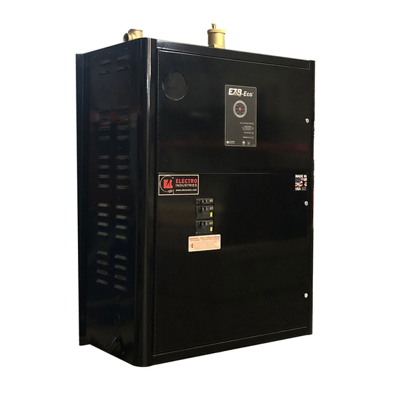
ELECTRO-BOILER
INSTALLATION & OPERATING INSTRUCTIONS
APPLICATION:
ACCESSORIES:
IMPORTANT:
Note:
This product meets the requirements of the ASME Boiler and Pressure Vessel Code.
Conforms to: UL STD.UL834
Certified to: CSA STD.C22.2#165
DO NOT DESTROY THIS MANUAL. PLEASE READ CAREFULLY AND KEEP IN A SAFE
PLACE FOR FUTURE REFERENCE BY A SERVICE TECHNICIAN.
09/01/2020
EZB-Eco
Model:
EZB-T1-05-240-1
EZB-T1-07-240-1
EZB-T1-10-240-1
EZB-T1-12-240-1
EZB-T1-15-240-1
EZB-T1-17-240-1
EZB-T1-20-240-1
The EZB-Eco is a packaged system complete with boiler vessel, expansion tank,
air eliminator and circulating pump. It is designed to be used in a variety of
radiant hydronic heating applications. These include radiant floor, baseboard or
radiator heating. These applications can be single or multiple zones. If any single
zone provides less than the minimum required GPM of the boiler, an Electro
Industries' zone controller option is highly recommended.
This series is equipped for load management interrupt with backup boiler output.
Electro Zone Controller models EB-ZEA-1 and EB-ZES8
Electro Dual Fuel Control Module EB-S-SB
The included expansion tank is shipped loose within the EZB-Eco enclosure. The
expansion tank must be installed prior to filling the system. See Mechanical
Installation section.
®
BI601
Advertisement
Table of Contents

Related Manuals for Electro Industries EZB-Eco EZB-T1-05-240-1


Summary of Contents for Electro Industries EZB-Eco EZB-T1-05-240-1
- Page 1 ELECTRO-BOILER ® EZB-Eco INSTALLATION & OPERATING INSTRUCTIONS Model: EZB-T1-05-240-1 EZB-T1-07-240-1 EZB-T1-10-240-1 EZB-T1-12-240-1 EZB-T1-15-240-1 EZB-T1-17-240-1 EZB-T1-20-240-1 APPLICATION: The EZB-Eco is a packaged system complete with boiler vessel, expansion tank, air eliminator and circulating pump. It is designed to be used in a variety of radiant hydronic heating applications.
-
Page 2: Table Of Contents
TABLE OF CONTENTS Description Page Introduction System or Water Flow Multiple Zones & Radiant Temperatures Zone Valves/Circulators Room Thermostat Placement Two-Temperature Operation or Feature Boiler/Piping Placement Installation Requirements Clearances Mechanical Installation – Under-Floor Radiation Electrical Hookup Water Fill Procedure Controller Setup Staging/Modulating Jumper Operational Tips Standby Switchover, SOT Timer... -
Page 3: Introduction
INTRODUCTION The EZB-Eco has been designed to be the complete system package for radiant heat applications. When properly sized, the EZB-Eco will provide the needed hot water to properly heat a space in a single zone or multiple zone application. With its unique WarmFlo technology, the EZB-Eco can easily modulate output based on the level of demand from a single or multi-zone system. -
Page 4: Multiple Zones & Radiant Temperatures
R and W to turn on the boiler. Electro Industries’ Zone Controllers – the Electro Industries’ zone controller priority zone has the ability to communicate with this EZB-Eco Series boiler and it will automatically switch to a high water temperature (150°... -
Page 5: Two-Temperature Operation Or Feature
bulb can later be pushed down this PVC conduit. If the slab is already poured without conduit for slab stat, use electronic remote sensing thermostat. B. Floor covering, medium to high insulation – use slab stat as described in paragraph A above. C. -
Page 6: Installation Requirements
ETL/Intertek certification, and manufacturer product liability. Electro Industries, Inc., cannot be held responsible for field modifications, incorrect installations, and conditions which may bypass or compromise the built-in safety features and controls. -
Page 7: Clearances
CLEARANCES SUGGESTED MINIMUM MINIMUM CLEARANCE SERVICE CLEARANCE LEFT SIDE 1 INCH 26 MM 12 INCHES 305 MM RIGHT SIDE 1 INCH 26 MM 12 INCHES 305 MM BACK REQUIRED CLEARANCE – 0 INCHES/0 MM FRONT REQUIRED CLEARANCE – 6 INCHES/153 MM REQUIRED CLEARANCE –... -
Page 8: Mechanical Installation - Under-Floor Radiation
MECHANICAL INSTALLATION – UNDER-FLOOR RADIATION CAUTION Electro Industries Inc. requires the use of dielectric isolation between the boiler supply and return piping when the boiler is plumbed using copper or any other dissimilar metal. Damage to the vessel caused by galvanic corrosion voids Electro Industries’ warranty. - Page 9 5. Piping between the EZB-Eco and hydronic system manifolds is shown on drawing BX603. When following this diagram, the water fill procedure becomes very simple and almost guarantees the removal of all air or prevents air locking problems. Experienced hydronic heating installers may be able to eliminate some components but the inclusion of these components guarantees installation and initial operating success.
-
Page 10: Electrical Hookup
ELECTRICAL HOOKUP Reference drawing BH601 1. 240/208-Volt Heating Power – route and install the proper current carrying conductors from service panel fuse or circuit breaker. See Specification Table and/or product nameplate for ratings. These models contain built-in circuit breakers and meet the requirement for local disconnect for appliances greater than 10 kW. -
Page 11: Water Fill Procedure
9. Flow Switch– a flow switch is not included or factory required for the boiler. However, one can be added to the LMC circuit. Simply place the field provided flow switch in series with this circuit. NOTE: The L/W (J3) jumper must be in the W position. WATER ADDITIVES/TREATMENT Water treatment is strongly suggested to prevent scale deposits, corrosion from acids, oxygen, and other harmful elements within the specific water supply. -
Page 12: Controller Setup
CONTROLLER SETUP Front Dial Non-Outdoor Reset – simply set the knob to the desired outlet temperature on the front panel decal. This control strategy is accomplished via disconnecting the outdoor sensor and performing a power reset to the boiler (low voltage power cycle). Outdoor Reset –... -
Page 13: Staging/Modulating Jumper
Staging/Modulating Jumper The control board on the EZB-Eco boiler is a universal controller with the capability of interfacing with many different models of TS Electro-Boilers. The correct setting of this jumper is determined on the model of the boiler you are working with. -
Page 14: Standby Switchover, Sot Timer
Manual Reset Hi-Limit At the top of the vessel there will be either two or three surface mount hi-limits preset at 205° F. There is no light indicator associated with these safety hi-limits. Also these 205° F safety limits break the L2 current carrying 240/208-volt wire going to the elements. -
Page 15: Replacement Parts List
Replacement Parts WFS2 Water sensor (ST), 5 ft. WFS25F Outdoor sensor (OT), 25 ft. EB5623 Control board UFUSE0443 2-amp, fast blow fuse 4038KIT Triac switch module 5128C Heating relay 5535 Safety hi-limit, manual reset, 205° F 5537G Safety hi-limit, auto reset, 190° F 5453 Relief valve, 30 PSIG 5456... -
Page 16: Troubleshooting/Repair Helps
TROUBLESHOOTING/REPAIR HELPS 1. This WarmFlo controller contains several interference suppression components, but as an electronic logic product, unpredictable and unusual transients or interference may sometimes cause strange results. If the WarmFlo controller is acting strange, one immediate step would be power down reset. Simply turn off boiler power or breaker number 1, when the green LED goes out, count to 1Ø, and re-energize power supply. -
Page 17: Operational Information
OPERATIONAL INFORMATION Normal heating operation – when there is a heat call from the thermostat (24VAC present on the control board W-C terminals) the boiler pump will start and three indicator lights will illuminate on the front of the EZB-Eco: ... -
Page 18: Bx603
EZB MECHANICAL PIPING SCHEMATIC EZB BOILER WATER SUPPLY BALL VALVE 1" X 1" X 3/4" TEE 1" PIPE 1" PIPE NIPPLE BALL VALVE 1" X 1" X 3/4" TEE DRAIN VALVE (THREADED INTO TEE) MANIFOLD Electro Industries, Inc. BX603 REV.A 04/28/20 Monticello, MN 55362 (763)295-4138... -
Page 19: Uaw429
UAW429 Rev. A 5/7/20... -
Page 20: Bh601
EZB-**-** EZB SERIES HOOKUP, INSTALLATION BH601 Rev. A 05/04/20 05/04/20 1 of 1 BH601 A... -
Page 21: Uaw428
UAW428 Rev. A 05-04-20... - Page 22 OILER CCESSORIES OILER CCESSORIES ZONE CONTROLLER This will simplify your wiring and make zoning applications much easier. In addition, enhanced communicating features have the ability to stage the electric boiler based upon the connected zone capacity. Pumps, Actuators, Valves Standard Features •...
- Page 23 Electro Industries’ boilers come standard equipped with outlet temperature/pressure gauge, pressure relief safety valve, and when applicable, the WarmFlo electronic control sensors.
-
Page 24: Xx017
Limited Product Warranty Effective November 1, 2009 Electro Industries, Inc. warrants to the original owner, at the original installation site, for a period of two (2) years from date of original purchase, that the product and product parts manufactured by Electro Industries, Inc. - Page 25 The decision whether to repair or, in the alternative, replace products or product parts shall be made by Electro Industries, Inc. or its authorized representative.
Need help?
Do you have a question about the EZB-Eco EZB-T1-05-240-1 and is the answer not in the manual?
Questions and answers