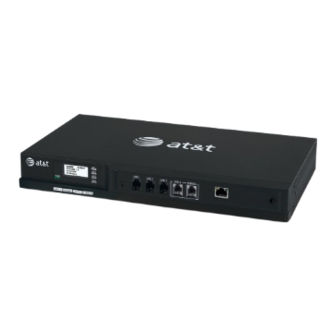
AT&T Syn248 Quick Start Manual
Hide thumbs
Also See for Syn248:
- User manual (136 pages) ,
- Quick start manual (19 pages) ,
- Installation and configuration manual (132 pages)
Advertisement
Quick Links
Download this manual
See also:
User Manual
Syn248
System Installation
tm
Quick Start Guide
For complete installation information,
see the Syn248 Installation and Configuration Guide,
available at www.telephones.att.com/smb.
1
System Components and Tools Required
• SB35010 Gateway You can install up to two Gateways to support
up to eight telephone lines.
• SB35020 Desksets The system supports up to 24 Desksets.
• CAT 5 LAN cables One per Deskset/Gateway is included.
• Power adapters for Gateways and Desksets (included). If your Local
Area Network (LAN) switch supports Power over Ethernet (PoE),
you can power the Desksets through the switch instead of using
adapters. Check your LAN switch specifications.
• LAN switch If using PoE to power Desksets, the switch ports must
provide PoE Class 2.
•
An Internet connection is recommended to provide accurate system
time and enable software updates.
• Screwdrivers/hardware for wall-mounting/rack-mounting Syn248
devices. Gateway rack-mounting brackets and screws are included.
System Diagram
Blue
lines: Telephone
Red
lines: Ethernet/CAT 5
2
Install the Gateway
You can place the Gateway on a tabletop, mount it into a standard 19-
inch metal rack, or wall mount it.
Rack-mounting
19 in. (48.3 cm)
3
Connect the Telephone Lines to the Gateway
Do not connect power to the Gateway yet.
If your phone company provides you with Centrex service, see the
Syn248 Installation and Configuration Guide before proceeding.
Connect telephone lines to the Gateway LINE ports using the supplied
cables. Ensure that the lines are configured as you ordered them from
Wall-mounting
your service provider, and that you have decided which lines will be
LINE 1, LINE 2, and so on for your Syn248 system.
If you subscribe to Digital Subscriber Line (DSL)
high-speed Internet service through your telephone
line, plug a DSL filter between each telephone line
with DSL service and the telephone wall jack.
7 7/8 in.
Optional: Connect an analog phone to the BYPASS port for use during
(20 cm)
a power outage. During a power outage, calls on the line connected to
Gateway LINE 4 are routed to the BYPASS port.
Advertisement

Summary of Contents for AT&T Syn248
-
Page 1: System Diagram
• CAT 5 LAN cables One per Deskset/Gateway is included. your service provider, and that you have decided which lines will be LINE 1, LINE 2, and so on for your Syn248 system. • Power adapters for Gateways and Desksets (included). If your Local... - Page 2 LEDs should turn off for each line you connected See the Syn248 Installation and Configuration Guide, available from in Step 3, indicating that the lines have calibrated to the Gateway and you can now make calls on those lines.


Need help?
Do you have a question about the Syn248 and is the answer not in the manual?
Questions and answers