Table of Contents
Advertisement
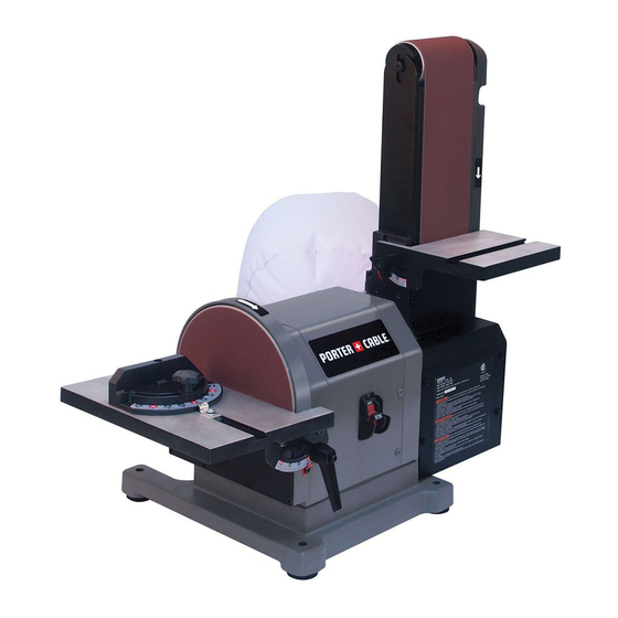
4 IN. x 8 IN. (102 MM x 203 MM)
BELT / DISC SANDER
PONCEUSE À BANDE/DISQUE DE
102 MM x 203 MM (4 PO x 8 PO)
LIJADORA DE CORREA / DISCO DE
102 MM x 203 MM (4 PULG. x 8 PULG.)
Instruction Manual
Manuel d'instructions
Manual de instrucciones
www.portercable.com
INSTRUCTIVO DE OPERACIÓN, CENTROS
DE SERVICIO Y PÓLIZA DE GARANTÍA.
ADVERTENCIA: LÉASE ESTE
CATALOG NUMBER
INSTRUCTIVO ANTES DE USAR EL
PCB420SA
PRODUCTO.
1
Advertisement
Table of Contents

Related Manuals for Porter-Cable PCB420SA


Summary of Contents for Porter-Cable PCB420SA
- Page 1 102 MM x 203 MM (4 PULG. x 8 PULG.) Instruction Manual Manuel d’instructions Manual de instrucciones www.portercable.com INSTRUCTIVO DE OPERACIÓN, CENTROS DE SERVICIO Y PÓLIZA DE GARANTÍA. ADVERTENCIA: LÉASE ESTE CATALOG NUMBER INSTRUCTIVO ANTES DE USAR EL PCB420SA PRODUCTO.
-
Page 2: Table Of Contents
TABLE OF CONTENTS SECTION PAGE PRODUCT SPECIFICATIONS ......................... CALIFORNIA PROPOSITION 65 ........................SAFETY GUIDELINES - DEFINITIONS ......................POWER TOOL SAFETY ..........................BELT / DISC SANDER SAFETY ........................ELECTRICAL REQUIREMENTS AND SAFETY ....................TOOLS NEEDED FOR ASSEMBLY ......................... CARTON CONTENTS ............................KNOW YOUR BELT / DISC SANDER....................... -
Page 3: Safety Guidelines - Definitions
SAFETY GUIDELINES - DEFINITIONS WARNING ICONS Your power tool and its Instruction Manual may contain “WARNING ICONS” (a picture symbol intended to alert you to, and/or instruct you how to avoid, a potentially hazardous condition). Understanding and heeding these symbols will help you operate your tool better and safer. Shown below are some of the symbols you may see. SAFETY ALERT: Precautions that involve your safety. -
Page 4: Power Tool Safety
POWER TOOL SAFETY NOTE: Glasses or goggles not in compliance with GENERAL SAFETY INSTRUCTIONS ANSI Z87.1 could seriously injure you when they BEFORE USING THIS POWER TOOL break. Safety is a combination of common sense, staying alert and knowing how to use your power tool. WEAR A FACE MASK OR DUST MASK. -
Page 5: Belt / Disc Sander Safety
BELT / DISC SANDER SAFETY 15. DO NOT sand with the workpiece unsupported. 1. USE sander on horizontal surfaces only. Operating the sander when mounted on non-horizontal Support the workpiece with the backstop or table. surfaces might result in motor damage. Plan your work support. -
Page 6: Electrical Requirements And Safety
ELECTRICAL REQUIREMENTS AND SAFETY POWER SUPPLY AND MOTOR SPECIFICATIONS and burning out of the motor. The table below shows the correct size to use depending on cord length and WARNING nameplate ampere rating. If in doubt, use the next heavier gauge. The smaller the gauge number, the To avoid electrical hazards, fire hazards, or damage heavier the cord. -
Page 7: Tools Needed For Assembly
TOOLS NEEDED FOR ASSEMBLY CARTON CONTENTS UNPACKING AND CHECKING CONTENTS Supplied Not Supplied Carefully unpack the belt / disc sander and all its parts, and compare against the list below and the illustration on the next page. Place the belt / disc sander on a secure surface and examine it carefully. - Page 8 UNPACKING YOUR BELT / DISC SANDER...
-
Page 9: Know Your Belt / Disc Sander
KNOW YOUR BELT / DISC SANDER KNOW YOUR BAND SAW 8 in. diameter Worktable knob sanding disc Belt worktable Miter gauge Angle pointer Worktable scale Disc worktable On/Off switch and switch key Worktable scale Mounting hole Worktable handle Angle pointer Belt worktable / backstop 4 in. -
Page 10: Assembly And Adjustments
ASSEMBLY AND ADJUSTMENTS Estimated Assembly Time: 10 - 20 minutes. MOUNTING WORKTABLE ON BELT (FIG. C, D ) The small worktable is used with the sanding belt. It WARNING should be used to support workpieces in all sanding To avoid injury, always keep the plug disconnected operations except inside curve applications. - Page 11 INSTALLING DUST EXHAUST AND DUST BAG MITER GAUGE (FIG. G) (FIG. E, F ) A miter gauge (1) is supplied with your sander and can be used with both sanding tables. The miter gauge body CAUTION can be adjusted from 0° to 60° right or left for angle or Sanding operations are inherently dusty.
- Page 12 Fig. H CAUTION Recommended Hardware To avoid trapping the workpiece or fingers between (not supplied) the worktable and sanding disc, the worktable edge 1. Mounting bolts should be positioned a maximum of 1/16 in. 2. Lock washer 3. Hex nut (1.6 mm) from sanding disc plate.
- Page 13 ADJUSTING BELT TABLE ANGLE (FIG. J) 1. The belt table (2) can be tilted from 0° to 45° by loosening the table lock knob (4) at the left sides of belt table. 2. Tilt the belt table to the desired angle. 3.
-
Page 14: Operation
OPERATION BELT HORIZONTAL SANDING (FIG. M) CAUTION CAUTION The belt/disc sander is designed to perform sanding To avoid trapping the workpiece or fingers between operations on surface, and edge grain. The sander the worktable and sanding belt, the worktable will also perform freehand forming and contouring edge should be positioned a maximum of 1/16 in. - Page 15 BELT VERTICAL SANDING (FIG. O, P) Freehand sanding of outside curves should be done on Your belt / disc sander - belt station can sand vertically the sanding disc (1). Keep fingers a minimum of 1 in. as well as horizontally. Depending on operator needs (25.4 mm) from the sanding disc.
-
Page 16: Maintenance
MAINTENANCE REPLACING SANDING BELT (FIG. U, V) WARNING WARNING For your safety, turn switch OFF and remove • the power cord from the electrical outlet before To avoid injury, turn switch OFF and disconnect the adjusting or performing maintenance on your plug from the power source before removing and sander. - Page 17 Fig. U Fig. V LUBRICATION Ball bearings are grease packed at the factory and require no further lubrication. Use a paste wax to ensure smooth operation on all moving table parts. Do not use any lubrication on the belt platen as this might end up on the wheels, causing them to slip.
-
Page 18: Troubleshooting Guide
Use only identical replacement parts. For a parts list or to order parts, visit our service website at www.portercable. com. You can also order parts from your nearest Porter-Cable Factory Service Center or Porter-Cable Authorized Warranty Service Center. Or, you can call our Customer Care Center at (888) 609-9779. -
Page 19: Accessories And Attachments
Since accessories, other than those offered by Porter- Cable, have not been tested with this product, use of such accessories with this tool could be hazardous. To reduce the risk of injury, only Porter-Cable recommended accessories should be used with this product. -
Page 20: Parts List
PARTS LIST 4 IN. x 8 IN. (102 MM X 203 MM) BELT / DISC SANDER PARTS LIST Description Size Description Size Description Size X45E RUBBER FOOT X43V DRIVE PULLEY X42D TUBE CONNECTOR X45D PHILIPS SCREW M4×10 X43U INNER HEX SCREW M8×12 X42C CAPACITOR SUPPORT1... - Page 21 4 IN. x 8 IN. (102 MM X 203 MM) BELT / DISC SANDER SCHEMATIC X4BG X4CC X4BJ X42S X41W X42T X4BH X4CA X44B X4BW X41V X440 X4BL X4CA X44B X42T X4BW X440 X43W X42W X42X X4BK X43S X42V X42Y X430 X4BV X43R...
- Page 22 NOTES...
- Page 23 NOTES...
-
Page 24: Warning
In addition to the warranty, PORTER-CABLE tools are covered by our: 1 YEAR FREE SERVICE: PORTER-CABLE will maintain the tool and replace worn parts caused by normal use, for free, any time during the first year after purchase.
Need help?
Do you have a question about the PCB420SA and is the answer not in the manual?
Questions and answers
How to change sanding belt
To change the sanding belt on a Porter-Cable PCB420SA:
1. Turn off the sander and disconnect it from the power source.
2. Remove the belt worktable.
3. Position the belt work support frame horizontally.
4. Loosen the inner hex screw using a 5 mm hex wrench (do not remove it).
5. Remove the two screws on the belt cover using a Phillips head screwdriver.
6. Use the quick release lever to release belt tension.
7. Remove and replace the sanding belt (4 in. wide × 36 in. long).
8. Reassemble the belt cover and worktable.
9. Check and adjust belt tracking if needed.
This answer is automatically generated