Table of Contents
Advertisement
Quick Links
Advertisement
Table of Contents

Related Manuals for Kathrein UFS 702si


Summary of Contents for Kathrein UFS 702si
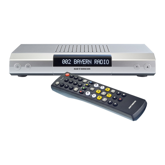
- Page 1 Operator‘s manual DVB Satellite Receiver UFS 702sw/si...
-
Page 2: Preface
We wish you good reception and much pleasure using your new DVB satellite receiver. Yours, The KATHREIN team The channels available on the satellites and transponders are subject to continual change. If changes do occur, the new channels have to be set in the receiver because the factory preset programming corresponds to the status on the date of manufacture. -
Page 3: Table Of Contents
Contents Preface Contents Safety instructions - important notes Receiver features Controls, displays and connections Important note on setting up receiver on a UFO ® micro system Connection and set-up Remote control Operating instructions Menu concept Menu tree Language selection - OSD On-Screen Displays (OSD) Channel notifications Error signalling... - Page 4 Contents Satellites Satellites (for experts) Setting and activation Enable Installation Time offset Language/character Set Select language Select character set (factory setting - “Latin”) Signal paths (TV, VCR, picture format, record, digital audio) TV Scart, VCR Scart Picture format Digital audio VCR signals LNB settings DiSEqC...
-
Page 5: Safety Instructions - Important Notes
Safety instructions - important notes... -
Page 6: Receiver Features
Receiver features The UFS 702si and UFS 702sw receivers are suitable for receiving FTA digital satellite TV and radio programmes. In addition to providing high-quality pictures and sound, these receivers also feature an attractive design in a modern housing. Despite their small size, the receivers have all of the... -
Page 7: Controls, Displays And Connections
Controls, displays and connections View of front panel (fl ap folded down) View of rear panel Front panel controls and displays 1. On/Off switch (with mains disconnect) 2. TV/R button for switching between TV and radio mode 3. 16-character alphanumeric display for channel names, radio data etc. -
Page 8: Lcd Display
Controls, displays and connections LCD Display The channel number and channel name are displayed on a 16-character LCD display. Display of TV channel and channel name during numerical entry (channel selection) Display of TV channel number and channel name upon completion of numerical entry. -
Page 9: Important Note On Setting Up Receiver On A Ufo ® Micro System
Important note on setting up receiver on a UFO ® micro system When registering the receiver to a UFO matrix EXU 544, you must do the following: - Connect the receiver to the TV set, but do not yet connect it to the ESU 32 antenna socket. -
Page 10: Connection And Set-Up
Connection and set-up Connecting the unit Sat IF Connections Reception requirements Reception system presets The following section is intended specifi cally for specialist dealers. You only need to pay attention to this section if you are carrying out the installation yourself. The “Connection examples”... -
Page 11: Inserting Batteries Into The Remote Control
Connection and set-up TV and Video recorder connection Audio connection Dolby connection Inserting batteries into the remote control Connect the satellite receiver (TV Scart socket) and the TV set using a Scart cable (see “Connection example”). If your TV has a stereo feature, you can receive the sound in stereo via the Scart connection. -
Page 12: Remote Control
Remote control Sound on/off ON mode, numerical input for channels, parental control etc. Select main menu (red) Favourites list selection (green) TV switching voltage and channel arrangement/pool Volume Quit menu, return to last channel Confi rm entry, select channel list (when pressed twice) Cursor operation in channel pool... -
Page 13: Remote Control Rc
For the fi rst receiver’s remote (address 1) press the second receiver and for the fourth receiver (red) = Kathrein UFD 5xx code for remote control RC 400 The RC 600 and RC 650 remote controls cannot be replaced! for second ;... -
Page 14: Operating Instructions
Operating instructions Menu concept Note: Pay attention to the bar at the bottom of the on-screen display. This provides hints on what to do next. The structure of the menu concept is based on logical operating sequences. You will fi nd detailed descriptions of the selected menu items in the relevant sections of the operating manual! The selected menus, sub-menus and options, as well as... -
Page 15: Menu Tree
Operating instructions Menu tree Main menu Channels Search Satellites Installation Language selection - OSD Favourites list Channel pool Favourites names Parental control Satellites Transponder Manual Time offset Language Signal paths DiSEqC™ Various The language for the on-screen display is set as follows: →... -
Page 16: On-Screen Displays (Osd)
On-Screen Displays (OSD) Channel information TV channel information Selected channel or favourites list Channel number Start and end time of the current and next programme Radio channel information Error signalling F = FTA (unencrypted) channel/ $ = encrypted channel A = two or more language channels (soundtracks) available ( ... -
Page 17: Channel Hopping Display
On-Screen Displays (OSD) Channel hopping display Channel list – TV/radio Press the button to display the last four selected channels. Press the relevant cursor button ( select a channel. Press the button twice to display a list sorted by channel number (see “Channel selection”, “Channel list”. -
Page 18: Channel Selection
Channel selection Switch between TV/radio mode Channel selection using number buttons and buttons Channel list – TV/radio Press the button (blue) to switch between TV and radio mode and then select the respective channels. Channel selection works in the same way in both modes. Use the number buttons to select a channel directly (“0”... -
Page 19: Channel Hopping Display
Channel selection Channel hopping display Select last channel Favourites list Press the button to display the last four selected channels. Press the relevant cursor button ( select a channel. Press the button to switch between the last two selected channels. Press the button (red) to display the favourites lists. -
Page 20: Epg - Electronic Programme Guide
EPG - Electronic Programme Guide (Electronic information on the current and upcoming programmes. The information provided is determined by the programme providers, and differs widely from programme to programme. Many programmes are broadcast with no usable ancillary information (SI data). The same is true with regard to the programme previews. - Page 21 EPG - Electronic Programme Guide Press the button (red dot) to transfer a programme from the programme preview directly to the timer menu (see “Timer”). Press the button to exit the EPG.
-
Page 22: Channels Menu - Channel Management
Channels menu – channel management Digital television technology makes a large number of channels available. A reception unit suitable for the ASTRA 19° East und EUTELSAT/HOTBIRD 13° East satellites allows you to receive over 800 FTA TV and radio programmes. To allow you to manage and control this range of channels, the memory for the lists is divided into two sections: - one channel pool for radio and TV respectively, each with... -
Page 23: Favourites List/Channel Arrangement (Move, Delete, Copy)
Channels menu – channel management Favourites list/channel arrangement (move, delete, copy) Path: MENU>Main menu>Channels> Select the “Channels” menu using the menu button buttons on the main menu and Use the buttons to select the further options. If there is another sub-menu layer, press the If there is no further sub-menu layer, access the selection menu with the button. - Page 24 Channels menu – channel management In the “Channel arrangement” menu, the following actions can be performed on channels: - Move - Delete - Copy The “Channel arrangement” menu shows the currently selected favourites list in the left-hand window and the channels available in the pool in the right-hand window.
-
Page 25: Move
Channel menu – channel management Note: Move Delete You should delete uninteresting channels, test cards or any other “junk programming” from your favourites list. Use the button to switch the menu display transparency between variable and fi xed (fi xed is non-transparent). In ‘var’... -
Page 26: Copy
Channel menu – channel management Copy Note: Note: • Select the favourites list in the left-hand window using the button. • Select the target area for the channels to be inserted with buttons or by entering the channel number – the blue arrow points between the two channels where the new channel will be inserted •... -
Page 27: Move Channel Block
Channel menu – channel management Move channel block answering the query “Save changes?” with “NO” i.e. press button again. The “Move”, “Delete” and “Copy” operations that are displayed in channel management can also be performed on channel blocks. • Select the favourites list in the left-hand window using button. -
Page 28: Delete Channel Block
Channel menu – channel management Delete channel block Copy channel block (copy from channel pool to favourites list) • Select the favourites list in the left-hand window using button • Move the fi rst channel of the block to be deleted into the green bar using the channel number •... -
Page 29: Change Names Of Favourites Lists
Channel menu – channel management Change names of favourites lists Channel pool Note: Path: MENU>Main menu>Channels>Favourites names You can also change the name of the favourites lists as required: • Select the entry fi eld to be changed {Name} using or the buttons and activate it with the •... -
Page 30: Delete One Channel/All Channels In Channel Pool
Channel menu – channel management Delete one channel/all channels in channel pool Antenna signal and reception parameters button If necessary, use the transparent. Use the buttons to navigate across lines and columns and select the required channels. All selected channels are immediately set by the receiver and displayed in the background. -
Page 31: Parental Control (Child Lock/Pin)
Channel menu – channel management Parental control (child lock/PIN) either no signal is being received or the signal is not valid (e.g. if the antenna is incorrectly aligned to a satellite with analogue signals). The signal strength and reception quality values are also shown on the display. - Page 32 Channel menu – channel management Note: Path: MENU>Main menu>Channels>Favourites lists Select the right-hand window with the sub-selection) and mark the necessary channels with the button (Pause). A question mark is placed in front of the “secured” channel (? channel name). To delete a “?”, move the marked channel back into the grey bar and press the Alternatively, channel marking can be performed directly in the channel pool.
-
Page 33: Search
Search Satellite search The newly found pro- grammes are also stored in the programme list, which is called up by pres- sing twice. However, unlike in programme pool, these are not attached to the end of the list, but rather to the end of each available broadcasting sa- tellite programme. -
Page 34: Manual Input (For Experts )
Search The newly found pro- grammes are also stored in the programme list, which is called up by pres- sing twice. However, unlike in programme pool, these are not attached to the end of the list, but rather to the end of each available broadcasting sa- tellite programme. -
Page 35: Videotext (Teletext)
Videotext (teletext) When you press the button, the receiver processes the videotext/teletext service data for your TV set to display, even when the signal is encrypted. During the search, the page which is being searched for is displayed in the top left-hand corner with the time and date displayed at the top right. -
Page 36: Timer
Timer Note: Manual Timer Setting If the timer recording is started in stand-by mode, the unit switches back to stand-by when recording is fi nished. Automatic Timer Setting If timer recording is star- ted in stand-by mode, the unit switches back to stand-by when recording is fi... -
Page 37: Vps
Timer “v” indicating VPS function active The time and date are retrieved from data transmitted transmitter. When changing from Summer to Winter time and vice versa, please adjust the “Time offset” in “Installation” menu. Central European Summer time = {+2 h}/ For Central European Winter time = {+1 h} Please... -
Page 38: Satellites
Satellites Satellites (for experts) Path: MENU>Main menu>Satellites The satellites ASTRA 19° and Hotbird 13° are “enabled” at the factory. Another six satellites, such as EUTELSAT/ HOTBIRD, are pre-programmed. When you expand your reception system, you can make the necessary settings for enabling the 6 pre-programmed satellites in the “Satellites”... - Page 39 Satellites Note: 2. Enter LO1 3. Enter LO2 At the factory LO1 and LO2 are preset to 9,750 MHz and 10,600 MHz. If the LNB-LO frequencies differ from the factory presets, enter the relevant values here. Activate with the number buttons Press to fi...
-
Page 40: Setting And Activation
Satellites Setting and activation Enable Path: MENU>Main menu>Satellites 1...8>Orbit position 1. Select Orbit position 1…4 2. Select Uncom switch The “Uncommitted switches” function is activated in menu item 2 = “Uncom switch”, by switching from “OFF” to a value between 1 and 16. Transmission takes place with the “FX”... -
Page 41: Installation
Installation Time offset Note: Note: Path: MENU>Main menu>Installation>Time offset Following power-up, or after a power outage, the time and date for the system clock (timer) are imported from the received data. To ensure the receiver’s time and date correspond to the local time, the variation from the standard time must be specifi... -
Page 42: Language/Character Set
Installation Language/character set Select language Select character set (factory setting - “Latin”) Signal paths (TV, VCR, picture format, record, digital audio) TV Scart, VCR Scart Path: MENU>Main menu>Installation>Language The menu languages available are German, English, Italian, French, Dutch, Portuguese, Spanish and Turkish. Automatic character set switching is defi... -
Page 43: Picture Format
Installation Picture format Digital audio Note: VCR signals TV > VCR (video return path) VCR signal (input signal at VCR Scart socket) 4:3 If 4:3 is set, all programmes are displayed in the regular 4:3 format. 16:9 When 16:9 is set, all programmes broadcast in widescreen format, and fl... -
Page 44: Lnb Settings
Installation VCR record LNB settings In standby The VCR Scart socket has two different modes for automatic VCR recording with the timer function: Standard The video signal (pin 19 on VCR Scart socket) to the VCR is always available. Pin 8 on the VCR Scart socket (switching voltage) is switched as an input, meaning that when you press the playback button on your video recorder, your satellite receiver... -
Page 45: Diseqc
Installation DiSEqC (Digital Satellite Equipment Control) 22 kHz signal Tone burst DiSEqC™ DiSEqC™ repeat Path: MENU>Main menu>Installation>DiSEqC On the DiSEqC menu the control signals must be set according to the needs of your satellite system. {OFF} 22 kHz inactive {High/Low} 22 kHz switches between High and Low band {Pos. -
Page 46: Ufo Various (Display Time, Rc, Lcd, Download, Factory Reset)
Various (display time, RC, LCD, download, factory reset) Display time function “UFO mini” and “UFO micro” are satellite systems ® ® specifi c to Kathrein. Please refer to the relevant operating manuals for the necessary setting parameters. mini {OFF}/{ON} ® Remote Freq. micro ®... -
Page 47: Lcd Display Settings
Installation LCD display settings Download Factory reset LCD backlight Used to set the illumination level of the display in 6 stages. Scroll speed Used to set the speed of the scrolling text in 5 stages. Time indicator The time indicator is switched off in standby. - Page 48 Installation Perform factory reset on device settings: PIN (security code): Time offset: Menu language: Character set: Signal paths: TV Scart VCR Scart TV>VCR VCR signal Picture format VCR record Digital audio In standby DiSEqC™ 22kHz signal Tone burst DiSEqC™ DiSEqC™ Repeat Satellites: Enable ASTRA Enable EUTELSAT13...
-
Page 49: Download-Over-Air (Software Update Via Satellite)
Installation Restore channels in favourites lists 1 and 8 Note: Download-Over-Air (Software update via satellite) Note: If you accidentally delete the channels in favourites list 1 (GENERAL) or 8 (HOTBIRD), you can reset the unit to delivery status here. Your other favourites lists (F2… F7) do not change. - Page 50 Installation Start the software download from the “INSTALLATION” menu after selecting the “Download” menu (6) by pressing the button. The download then runs through a number of phases, with each phase accompanied by relevant information messages. You can abort the various phases at any time. Search for the download channel on the ASTRA satellite.
-
Page 51: Video Recorder/Pvr Connection
Video recorder/PVR connection Recording Playback Note: Connect your recorder and the receiver (VCR socket) using a Scart cable. If you have a S-VHS (S-Video) recorder, from the “Installation” menu select the “Signal paths” sub-menu and change the selection (TV Scart VCR) so that the “YC” signal is output at the VCR socket. -
Page 52: Return Path
Video recorder/PVR connection Return path The video signal from the TV set can be returned to your recorder in standby mode. If you want to use this function, from the “Installation” menu select the “Signal paths” sub-menu and then choose “VCR signals”. -
Page 53: Audio Settings
Audio settings Setting the volume Muting Digital output Always follow operating instructions for your Dolby Digital system. Digital/analogue – audio mode Set the required volume level using the remote control of the receiver. A bar indicator is displayed on the screen to show the set volume. Press the button to mute the sound. -
Page 54: Analogue Outputs
Audio settings Analogue outputs in PCM format) or complex multi-channel surround signals (Dolby Digital/AC 3) can be transmitted on the digital socket. Press the button (yellow) to access the “Digital/analogue audio mode” menu. You can use this menu purely as an information display and press the quit it immediately, or you can change various settings. -
Page 55: Digital Output
Audio settings Digital output “AC 3 – general”: In the right-hand window you see the current signal status at the digital output (= digital cinch socket). If “PCM” is displayed, the digital signal is encoded in PCM format. If “AC 3” is displayed, the audio signal is encoded in Dolby Digital format. -
Page 56: Using The Front Panel
Using the front panel Backup operation Because there no number buttons, password/PIN- protected functions can be displayed. If you have misplaced your remote control, or if the batteries are empty, you can still operate your receiver from the front panel. The power switch, the TV/R button for switching between TV and radio mode and the channels are located on the front panel. -
Page 57: Receiver To Receiver Data Transfer
Receiver to receiver data transfer Preparation Channel list download Download operating system Your receiver is able to receive data from another receiver via its RJ11 port. For this, the two receivers are connected with a null modem cable. The transmitting receiver is the “master”, and the receiving receiver is the “slave”. -
Page 58: Technical Appendix
Technical appendix Technical features Channels • 2,000 memory slots each for TV and radio programmes • 8 customisable favourites lists each with 1,000 channel slots (e.g. for SPORT, NEWS, MUSIC categories, etc.) • 8 satellites (individually activated) • 24 characters for channel/station names •... - Page 59 • Videotext/teletext reinsertion (for viewing on TV) • Internal teletext (videotext) • 800 page teletext (videotext) memory • Prepared for UFO ® mini, UFO ® micro (Kathrein-specifi c) Software Update • Via data interface (RJ 11 port), separately for: • Via satellite separately for: General •...
- Page 60 TV/VCR output Audio output (analogue) Audio digital output (electrical) Audio digital output (optical) Data port General Ambient temperature limit Unit dimensions Weight UFS 702si 20210079 Silver 950-2150 dBµV DVB-S standard CCIR 601 (720 x 576 lines) MSymb/s MPEG-1 and 2 compatible...
-
Page 61: Accessories
Technical appendix Accessories Scart socket assignment VHS/S-VHS switching 1 infrared remote control (RC 660) 2 batteries 1.5 V, type: LR 03, size: AAA (micro) 1 Scart cable 1 operating manual Signal Right audio output Right audio input Left audio output Audio earth Blue earth Audio left input... -
Page 62: Connection Example
Technical appendix Connection example cinch HiFi system PVR (VCR) Electrical or optical Elektrischer oder optischer AC 3 digital sound Dolby Digital system... -
Page 63: Short Technical Guide
Short technical guide Channel package DiSEqC™ DiSEqC™ components DVB MPEG-2 EB/NO ratio The channel package for a digital transponder normally includes several TV and radio channels. Each channel package has a fi xed assignment for the transponder transmission frequency, for polarisation (horizontal or vertical), for the symbol rate and for the Viterbi rate or error rate. - Page 64 Short technical guide Symbol rate Transponder Video bit rate Viterbi rate The PID (Packet IDentifi cation) number is an identifi cation number for video signals and audio signals in the digital data stream of DVB-MPEG-2 signals. The receiver uses the PID number to create a unique assignment for the video and audio data transmission.
-
Page 65: Glossary
Rate of data transmission of satellite signal Time-shift function Time-shifted playback Timer function Clock function for pre-programmed switch on and off times Transponder See Short technical guide UFO ® micro and Kathrein-specifi c satellite signal processing systems UFO ® mini... - Page 66 Short technical guide VCR connection Video recorder connection Viterbi rate See Short technical guide (Y = brightness, C = colour signal) Video signal standard for S-VHS recorders Zapping Frequent programme changing using the remote control...
-
Page 67: Error Detection/Troubleshooting And Service
Error detection/troubleshooting and service In the event of a malfunction, fi rst check all the cable connections and operating states: 1. Receiver and TV set power plugs are connected to wall socket 2. Antenna cables on receiver input 3. Receiver and TV set correctly connected by a Scart or cinch cable 4. -
Page 68: Search For New Channels
Internet: www.kathrein.de KATHREIN-Werke KG • phone +49 8031 184-0 • Fax +49 8031 184-306 Anton-Kathrein-Straße 1 - 3 • P.O. Box 100 444 • 83004 Rosenheim GERMANY A channel has moved or is no longer present on the original frequency.
Need help?
Do you have a question about the UFS 702si and is the answer not in the manual?
Questions and answers