Advertisement
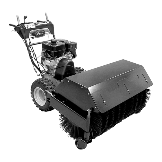
Power Brush 36
Owner/Operator Manual
Manuel Du Propriétaire/Utilisateur
E10
The use of any gasoline exceeding 10% ethanol (E10) or
10% MTBE will void the product warranty.
L'utilisation d'une essence contenant plus de 10% d'éthanol
(E10) ou de 10% de MTBE annulent la garantie.
ENGLISH
FRANÇAIS
Model
926057 – Power Brush 36
(Serial No. 000101 +)
04653900 4/13
Printed in USA
Advertisement
Table of Contents

Related Manuals for Ariens 926057


Summary of Contents for Ariens 926057
- Page 1 Power Brush 36 Owner/Operator Manual Manuel Du Propriétaire/Utilisateur Model 926057 – Power Brush 36 (Serial No. 000101 +) The use of any gasoline exceeding 10% ethanol (E10) or 10% MTBE will void the product warranty. L’utilisation d’une essence contenant plus de 10% d’éthanol (E10) ou de 10% de MTBE annulent la garantie.
-
Page 2: Table Of Contents
MODEL AND SERIAL NUMBERS your product, please fill out, sign and return When ordering replacement parts or making the product registration card to Ariens or go service inquiries, know the Model and Serial to www.ariens.com. numbers of your unit and engine. -
Page 3: Safety
DISCLAIMER NOTE: To locate your nearest Ariens Dealer, go to www.ariens.com on the Internet. Ariens reserves the right to discontinue, make changes to, and add improvements WARNING: Improper assembly or upon its products at any time without public adjustments can cause serious notice or obligation. - Page 4 REQUIRED OPERATOR TRAINING 1. WARNING! Original purchaser of this unit was instructed by the seller on safe and proper operation. If unit is to be used by someone other than Danger! original purchaser; loaned, rented or sold, ALWAYS provide this manual and any needed safety training before operation.
- Page 5 Keep clear of brush while fines or penalties. Emission controls and engine is running. components can only be adjusted by an Ariens Company dealer or an authorized engine manufacturer's service center. Contact your Ariens Company Equipment Retailer concerning emission controls and component questions.
- Page 6 Keep children and people away. Keep Always stand clear of the discharge area children out of work area and under watchful when operating this unit. care of a responsible adult. Fumes from engine exhaust can cause injury NEVER allow children to operate or play on or death.
- Page 7 Adjust brush height before operating. Engage If fuel is spilled on clothing, change clothing traction drive clutch before attachment clutch. immediately. If brush is set too low or if terrain is irregular Adjust brush height before operating. Refer to brush can drive machine rearward. Operation.
-
Page 8: Assembly
ASSEMBLY WARNING: AVOID INJURY. Read and understand the entire Safety section before proceeding. Tools Required: • Tire Gauge • Pliers • 1/2-In. 3/8-In, 7/16-In, and 9/16-In Wrench and/or Adjustable Wrench Unpacking Unit WARNING: Dropping or tipping over boxed unit could result in personal injury or damage to unit. - Page 9 Check Tire Pressure Check Engine Crankcase Oil Check tire pressure and adjust to the IMPORTANT: Engine is shipped with 5W-30 pressure listed on tire sidewall. oil in crankcase. Refer to Engine Manual for detailed instructions. CAUTION: Avoid injury! Explosive Fill Engine Fuel Tank separation of tire and rim parts is Refer to Engine Manual for proper fuel type possible when they are serviced...
-
Page 10: Controls & Features
CONTROLS AND FEATURES Figure 4 1. Traction Drive Clutch Lever 11. Height Adjustment Wheels 2. Speed Selector Lever 12. Fuel Shut Off Valve 3. Attachment Clutch Lever 13. Fuel Fill Cap 4. Brush Angle Lock Lever 14. Choke 5. Recoil Starter Handle 15. -
Page 11: Operation
OPERATION Dual Handle Interlock WARNING: AVOID INJURY. Read When Attachment Clutch and then Traction and understand the entire Safety Drive Clutch are engaged, the Attachment section before proceeding. Clutch Lever will remain engaged (down) if released. To stop attachment, release Traction Drive Clutch Lever and both clutches will disengage. - Page 12 Throttle Lever Fuel Shut-Off Valve The throttle controls the engine speed. To IMPORTANT: The fuel shut-off valve MUST increase or decrease engine speed, adjust to: be in the closed position prior to transporting the unit. 1. Fast (normal or warm starts) to left The fuel shut-off valve has two positions: 2.
- Page 13 3. Lift the brush head assembly off the FILLING FUEL TANK ground and reverse the unit to move it away from the swept area. WARNING: AVOID INJURY. Read 4. Stop engine and allow all moving parts and understand the entire Safety to stop.
- Page 14 5. Fill fuel tank to within 1/2 in (1.27 cm) If clutches do not engage or disengage below bottom of filler neck. See properly, adjust or repair before operation Specifications on page 29 for fuel tank See Attachment Clutch Adjustment on capacity.
- Page 15 De-thatch in the spring to clear winter undergrowth. IMPORTANT: Use only Ariens extension cord (P/N 02483100) or an equivalent cord that is Adjust brush height so it just touches the rated for a minimum of 13 amps, grounded, grass.
-
Page 16: Maintenance
MAINTENANCE Ariens Dealers will provide any service or 2. Remove belt cover. adjustments which may be required to keep 3. Remove hardware attaching remote your unit operating at peak efficiency. Should trigger cable to brush assembly and detach cable. engine service be required, contact a Ariens dealer or an authorized engine 4. - Page 17 OPERATING POSITION MAINTENANCE SCHEDULE (Figure 7) Yearly To connect the brush attachment to traction Service Each Daily Every unit: Performed (8 hrs.) 25 hrs 1. Place attachment belts onto attachment pulley. Check Dual NOTE: Holding down the attachment clutch Handle •...
- Page 18 CHECK CLUTCH OPERATION CHECK ENGINE OIL Brush must stop quickly when attachment The engine crankcase oil should be checked clutch lever is released. every 8 hours of operation. Oil level MUST be maintained in safe operating range on Wheels must stop quickly when traction drive dipstick at all times or engine damage will clutch lever is released.
- Page 19 GENERAL LUBRICATION 3. Apply a few drops of oil to the roller chain at the beginning of the season or (Figure 8) every 25 operating hours. 1. Place unit into the service position (See NOTE: Brush attachment gear case is Service Position on page 16).
-
Page 20: Service & Adjustments
SERVICE AND ADJUSTMENTS SPEED SELECTOR ADJUSTMENT WARNING: AVOID INJURY. Read and understand the entire (Figure 8) Safety section before To adjust: proceeding. 1. Disconnect adjustment pivot pin from speed selector lever. RECOIL GUARD FOAM COVER 2. Place the speed selector in the fastest INSTALLATION forward speed position. - Page 21 OS7191 OS7185 1. Shift Rod 1. Attachment Clutch Cable 2. Adjustment Barrel 2. Adjustment Pivot Pin 3. Speed Selector Lever 3. Jam Nut 4. Hairpin Figure 11 Figure 10 3. With the attachment clutch disengaged, ATTACHMENT CLUTCH check that the attachment idler arm lightly touches the frame (Figure 12).
- Page 22 Check Attachment Idler Arm Some components removed for Roller Clearance clarity of illustration. (Figure 13) NOTE: It will be difficult to check the measurement inside the frame. Use a 1/2 in. (12.7 mm) minimum spacer as a gauge to check the clearance between the roller and the frame.
- Page 23 ATTACHMENT DRIVE BELTS Check belt finger clearance here. With the REPLACEMENT attachment clutch engaged, there should be less than 1/8 in. (3 mm) clearance between the belts and the belt finger. The WARNING: ALWAYS remove belt finger should not touch the belts. key and-or wire from spark plug before assembly, maintenance or service.
- Page 24 2. To gain belt clearance, back out the stop FRICTION DISC REPLACEMENT screw from the frame until the drive plate (Figure 17) assembly can swing past it (Figure 15). 1. Place the unit into the service position 3. Pull idler away from traction drive belt (See Service Position on page 16).
- Page 25 OS7225 1. Friction Disc 7. Pinion Sprocket 2. Self-Tapping Screws 8. Drive Plate Assembly 3. Carrier 9. Chain 4. Spring Clip Pin 10.Bottom Cover Rear Cap Screws 5. Hex Shaft 11.Bottom Cover Side Cap Screws 6. Bearing Flange 12.Drive Plate Assembly Stop Screw Figure 17 BRUSH SEGMENT REPLACEMENT...
- Page 26 3. Loosen each bearing setscrew and slide bearings inward, away from horizontal end supports. IMPORTANT: Brush gearbox splined shaft will separate from brush housing u-joint. Support splined shaft to prevent damage (Figure 19). 1. Brush Segment 1. Flanged Bolts 2. U-Joint 2.
-
Page 27: Storage
IMPORTANT: Brush segments must be FUEL SYSTEM aligned properly so they do not nest together Gasoline left in the fuel system for extended (Figure 19). periods without a stabilizer will deteriorate, 7. Remove used brush segments and resulting in gum deposits in the system. replace with new segments. -
Page 28: Troubleshooting
07231000 Traction Drive Belt 07200601 Attachment Drive Belt (Set of 2) 21547200 Spark Plug 00170800 Friction Disc 00036800 Ariens Hi-Temp Grease (Three 3 oz. cartridges) 03972500 Recoil Guard Foam Cover To obtain a complete parts manual, find your model and serial number. Then go to www.ariens.com. -
Page 29: Specifications
SPECIFICATIONS Model Number 926057 Engine Subaru EX27 16.2 (265) Engine Displacement – in (cc) Fast Idle Speed – RPM 3800 ±100 Starter 120VAC Electric and Recoil Fuel See Engine Manual Tank Capacity – qts. (L) 6.3 (6.1) Clearing Width – in. (cm) 36 (91.44) -
Page 30: Warranty
® ® Sno-Thro , Sno-Tek Chore Performing Equipment Limited Warranty Ariens Company (Ariens) warrants to the original purchaser that Ariens, Gravely, Parker, and Countax ® ® brand chore performing equipment (including Sno-Thro and Sno-Tek equipment) purchased on or after 1/1/2013 will be free from defects in material and workmanship for the time period noted in the chart below. - Page 31 Register the product immediately at the time of sale. If the dealer does not register the product, the customer must complete the product registration card in the literature package and return it to Ariens Company, or register the unit online at www.ariens.com, www.gravely.com, www.countax.com or www.parkersweeper.com.
- Page 32 Exclusions – Items Not Covered by This Warranty • Parts that are not genuine Ariens, Gravely, Parker or Countax service parts are not covered by this warranty and may void the warranty. • Damages resulting from the installation or use of any part, accessory, or attachment which is not approved by the Ariens Company for use with product(s) identified herein are not covered by this warranty.
- Page 34 Ariens Company 655 West Ryan Street Brillion, WI 54110 920-756-4688 Fax 920-756-2407 www.ariens.com...
Need help?
Do you have a question about the 926057 and is the answer not in the manual?
Questions and answers