Ariens Sno-Thro Professional Series Operator's Manual
Hide thumbs
Also See for Sno-Thro Professional Series:
- Service manual (84 pages) ,
- Operator's manual (34 pages) ,
- Operator's manual (32 pages)

Subscribe to Our Youtube Channel
Related Manuals for Ariens Sno-Thro Professional Series


Summary of Contents for Ariens Sno-Thro Professional Series
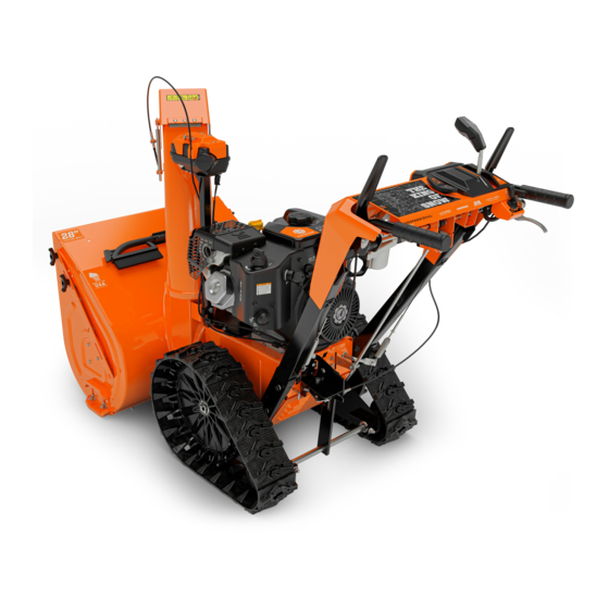
- Page 1 Sno-Thro ® Operator’s Manual Manuel du Utilisateur Professional Series With Hydrostatic Drive Models 926068 – Pro 28 EFI (SN 000101 +) 926070 – Pro 36 EFI (SN 000101 +) ENGLISH • 05136600A 3/17 FRANÇAIS Printed in USA...
-
Page 2: Table Of Contents
TABLE OF CONTENTS WELCOME ..... . 1 Check Auger Gearcase Oil ..14 Lubricate Unit. -
Page 3: Welcome
WELCOME Congratulations on your purchase and welcome to the Ariens family! Every snow thrower in the Ariens lineup is designed for long-lasting and unsurpassed performance. We are confident your machine will be part of your family for many years to come. -
Page 4: Safety
• BECOME ALERT! penalties. Emission controls and components • OBEY THE MESSAGE! can only be adjusted by an Ariens Company dealer or an authorized engine SIGNAL WORDS manufacturer's service center. Contact your The safety alert symbol above and signal Ariens Company Equipment Retailer... -
Page 5: Safety Decals
4. Notice NEVER direct discharge NOTICE: Indicates information or procedures towards persons or property that are considered important but not hazard that may be injured or related. If not followed, property damage damaged by thrown objects. could result. 5. Important Keep people away from unit IMPORTANT: Indicates general reference while operating. -
Page 6: Safety Rules
Complete a walk-around inspection of the 3. DANGER! unit to understand the unit, your work area and all safety decals. Understand how to operate all controls, the Danger! functions of all controls and how to STOP in an emergency. ROTATING PARTS! Keep Preparation clear of auger while engine Always check overhead and side clearances... - Page 7 Never attempt to make any adjustments Do not run the engine indoors, except when while the engine is running (except when starting the engine and for transporting the specifically recommended by manufacturer). snow thrower in or out of the building. Open the outside doors;...
- Page 8 Avoid contact with sharp edges; sharp Always refer to operator's manual for edges can cut. important details if the snow thrower is to be stored for an extended period. Do not throw snow higher than necessary. Maintain or replace safety and instruction labels as necessary.
- Page 9 Never secure from rods or linkages that could be damaged. Do not transport machine while engine is running. Accessories Use only Ariens Company-recommended attachments or accessories that are designed for your unit and that are appropriate to your use and can be used safely in your application.
-
Page 10: Controls & Features
CONTROLS & FEATURES Figure 3 1. Engine Key 16. Heated Hand Grip Switch 2. Fuel Tank and Cap 17. Scraper Blade 3. Electric Start Button 18. Drift Cutter (2) 4. Throttle Control Knob 19. Skid Shoe (2) 5. Oil Fill / Dipstick 20. -
Page 11: Engine Key
SPEED SELECTOR LEVER WARNING: Read and See Figure 6. understand the Safety section Controls the speed of forward and reverse before proceeding. travel. See Figure 3 for all controls and features locations. ENGINE KEY See Figure 4. Controls power to the engine. The key cannot be removed when in run position. -
Page 12: Traction Drive Clutch Lever (Left Side)
TRACTION DRIVE CLUTCH DISCHARGE CHUTE DEFLECTOR LEVER (LEFT SIDE) LEVER See Figure 8. See Figure 10. Allows unit to travel forward and in reverse. Moves discharge deflector up or down to control height of snow discharge. Figure 8 DUAL HANDLE INTERLOCK Figure 10 Allows auger / impeller to rotate without HEATED HAND GRIP SWITCH... -
Page 13: Operation
NOTICE: DO NOT run starter more than 10 E30 / E85 compatible. The maximum times at intervals of 5 seconds on / 5 seconds recommended ethanol content is 10%. Ariens off or overheating and damage may occur. recommends using a quality fuel stabilizer in all fuel. -
Page 14: Operate Unit
OPERATE UNIT 1. Rotate discharge chute and move deflector to desired positions. 2. Select desired speed. 3. Engage attachment clutch. IMPORTANT: For best snow-throwing results, ensure that throttle control knob is set to the Efficiency or higher position. NOTICE: Stop auger when traveling between work areas. -
Page 15: Transport Unit
• understand the Safety section Change Engine Oil ** before proceeding. General Lubrication • • Your Ariens dealer can provide service and Check Auger Gearcase Oil • • adjustments to keep your unit operating at Replace Fuel Filter • peak efficiency. Contact an authorized engine * After first use. -
Page 16: Service Parts
• DO NOT inflate tires above • 414 ml (14 oz) cartridge (1) 00036700 the recommended pressure. Ariens L3 Lube – 237 ml (8 oz) 00068800 • DO NOT inflate tires with a Shear Bolt and Nut 52100100 compressor; use a hand Fuel Stabilizer –... -
Page 17: Lubricate Unit
6.1 – 6.7 cm (2.4 – 2.6") from the flat surface of the gearcase cover. IMPORTANT: Ariens recommends using only Ariens L3 synthetic severe duty gear lube (see Service Parts on page 14). Using other lubricants will not automatically void unit... -
Page 18: Charge Battery
3. Hand rotate auger on auger shaft. 4. Align shear bolt holes in auger with shear bolt holes in shaft. 5. Insert bolts through holes. 6. Secure bolts with nuts. 7. Tighten bolts to 7.9 – 16.5 N•m (5.8 – 12.2 lb-ft). If a torque wrench is unavailable, tighten bolts until they no longer spin freely. -
Page 19: Adjustments
REPLACE SHEAR BOLTS ADJUSTMENTS IMPORTANT: Ariens recommends using only Ariens OEM shear bolts when replacing shear bolts. WARNING: AVOID INJURY. See Figure 18. Read and understand the Safety section before proceeding. 1. Align shear bolt holes in auger with shear bolt holes in the shaft. -
Page 20: Adjust Discharge Chute
2. Adjust nuts on chute cable. See Figure 24. • To adjust deflector lower, loosen lower nut and tighten upper nut. • To adjust deflector higher, loosen upper nut and tighten lower nut. 1. Discharge Chute Gear Cover 2. Rear Adjustment Nut 3. -
Page 21: Adjust Attachment Clutch & Brake
1. Hairpin 2. Trunnion 1. Attachment Clutch Cable 3. Bell Crank 2. Cable Adjustment Barrel 4. Jam Nut 3. Jam Nut 5. Shift Rod Figure 27 Figure 26 5. With the attachment clutch disengaged, ADJUST ATTACHMENT CLUTCH make sure auger idler arm lightly touches the frame. - Page 22 Check Attachment Idler Arm Roller • If there is less than 1.6 mm (1/16") gap, loosen idler adjustment nut and move idler Clearance away from belt or pulley. Position idler to 1. Place unit in service position and remove achieve a 1.6 mm (1/16") minimum brake bottom cover.
-
Page 23: Adjust Traction Drive Clutch
Check Belt Finger Clearance See Figure 32. With attachment clutch engaged, the belt finger located opposite the belt idler must be less than 3.2 mm (1/8") from belts, but must not touch the belts. To adjust belt finger: 1. Remove belt cover. 2. -
Page 24: Troubleshooting
Replace spark plug. Refer to engine manual. Engine will not start. Engine is faulty. See your Ariens dealer or authorized engine manufacturer’s service center. Battery is dead. See Charge Battery on page 16. See Controls & Features on page 8. Refer to the Service Guide for your unit. - Page 25 TROUBLESHOOTING Problem Probable Cause Correction Shear bolts are broken. See Replace Shear bolts on page 17. Attachment clutch / brake is not See Adjust Attachment Clutch & Brake on adjusted correctly. page 19. Impeller is frozen in place. Move unit to a warm place to thaw. Ice or debris is obstructing auger.
-
Page 26: Storage
ACCESSORIES SHORT TERM 1. Run auger / impeller for a few minutes to See your Ariens dealer for a complete list of remove loose or melting snow to prevent compatible accessories and attachments for impeller from freezing. -
Page 27: Specifications
SPECIFICATIONS Model Number 926068 926070 Description Hydro Pro 28 EFI Hydro Pro 36 EFI Engine Ariens AX EFI Gross Torque* – N•m (lb-ft) 27.1 (20.0) 420.0 (25.6) Displacement – cm Maximum RPM – No load 3600 ± 50 Electric Start 120V Fuel Tank Capacity –... -
Page 28: Warranty
Chore ® ® Performing Equipment Limited Warranty Warranty Ariens Company (Ariens) warrants to the original purchaser that Ariens, Gravely, Parker, and Countax ® ® brand chore performing equipment (including Sno-Thro and Sno-Tek equipment) purchased on or after 1/1/2016 will be free from defects in material and workmanship for the time period noted in the chart below. - Page 29 Register the product immediately at the time of sale. If the dealer does not register the product, the customer must complete the product registration card in the literature package and return it to Ariens Company, or register the unit online at www.ariens.com, www.gravely.com, www.countax.com or www.parkersweeper.com.
- Page 30 Exclusions – Items Not Covered by This Warranty • Parts that are not genuine Ariens, Gravely, Parker or Countax service parts are not covered by this warranty and may void the warranty. • Damages resulting from the installation or use of any part, accessory, or attachment which is not approved by the Ariens Company for use with product(s) identified herein are not covered by this warranty.
- Page 32 655 West Ryan Street Brillion, WI 54110 ariensstore.com ariens.custhelp.com parts.ariens.com...
Need help?
Do you have a question about the Sno-Thro Professional Series and is the answer not in the manual?
Questions and answers