Table of Contents
Advertisement
Owner/Operator Manual
Ръководство за работа на
ползвателя/оператора
Návod k obsluze
Betriebsanleitung
Manual del propietario/operador
Käyttöohjekirja
Manuel du propriétaire/utilisateur
Tulajdonosi/kezelői útmutató
Manuale del proprietario/operatore
Gebruikshandleiding
Brukerhåndbok
Instrukcja obslugi / operatora
Manualul proprietarului /
operatorului
Руководство владельца/
пользователя
Navodila za uporabo
Príručka majiteľa/obsluhy
Instruktionsbok
Kullanım Kılavuzu
926 Series
Sno-Thro
E10
®
Models
926321 – Pro 28
(SN 095000 +)
926324 – Pro 28 Track
(SN 095000 +)
926513 – Pro 32 12V
(SN 095000 +)
926516 – Pro 32 12V
(SN 000101 +)
04337415E 6/13
Printed in USA
Advertisement
Table of Contents

Related Manuals for Ariens Professional 32 - 12 Volt


Summary of Contents for Ariens Professional 32 - 12 Volt
- Page 1 926 Series Sno-Thro ® Models Owner/Operator Manual 926321 – Pro 28 Ръководство за работа на (SN 095000 +) ползвателя/оператора 926324 – Pro 28 Track Návod k obsluze (SN 095000 +) 926513 – Pro 32 12V Betriebsanleitung (SN 095000 +) Manual del propietario/operador 926516 –...
- Page 2 PROIZVAJALEC – ES VYHLÁSENIE O ZHODE, VYDANÉ VÝROBCOM – ÜRETİCİ TARAFINDAN DÜZENLENEN EC UYGUNLUK BEYANI We the undersigned, ARIENS COMPANY, certify that: Ние, долуподписаните от фирма ARIENS, удостоверяваме, че: My, nížepodepsaní, ARIENS COMPANY, prohlašujeme, že: Der Unterzeichnete, ARIENS COMPANY, bescheinigt, dass: Nosotros, los abajo firmantes, ARIENS COMPANY, certificamos que: Allekirjoittanut, ARIENS COMPANY, vakuuttaa, että: Nous, soussignés ARIENS COMPANY, certifions que:Alulírott, ARIENS COMPANY,...
- Page 3 Dátum – Data – Datum – dokumentace) / Director Product Conformance & War- Dato – Data – Data – Ariens Company ranty (Archivar der technischen Akte) / Director de con- дата – Datum – Dátum – Brillion, WI 54110-1072 USA formidad de los productos y de garantía (Conservador...
-
Page 4: Table Of Contents
PRODUCT REGISTRATION registration form in the unit literature package. They are printed on a serial number The Ariens dealer must register the product label, located on the frame of your unit. at the time of purchase. Registering the product will help the company process warranty claims or contact you with the latest service information. -
Page 5: Safety
4. Review recommended lubrication, maintenance and adjustments. 5. Review Limited Warranty Policy. 6. Fill out a Product Registration Card and return the card to the Ariens Company or go to www.ariens.eu. SAFETY The safety alert symbols above and signal words below are used on decals and in this WARNING: To avoid injury to hands manual. - Page 6 PRACTICES AND LAWS 1. DANGER! Practice usual and customary safe working precautions, for the benefit of yourself and others. Understand and follow all safety messages. Be alert to unsafe conditions and Danger! the possibility of minor, moderate, or serious injury or death. Learn applicable rules and laws in your area.
-
Page 7: Safety Rules
(CARB) regulations. Tampering with emission controls and components by unauthorized personnel may result in severe fines or penalties. Emission controls and components can only be adjusted by an Ariens Company dealer or an authorized engine manufacturer's service center. Contact your Ariens Company Equipment Retailer concerning emission controls and component questions. - Page 8 DO NOT operate unit without wearing Do not operate in reverse unless absolutely adequate winter outer garments. Wear necessary. ALWAYS back up slowly. Always adequate safety gear, including safety look down and behind before and while glasses with side shields, and protective backing.
- Page 9 NO smoking, NO sparks, NO flames. DO NOT change engine governor settings or ALWAYS allow engine to cool before over-speed engine. servicing. Fumes from engine exhaust can cause injury NEVER fill fuel tank when engine is running or death. DO NOT run engine in an enclosed or hot from operation.
-
Page 10: Assembly
ASSEMBLY Unfold Handlebar WARNING: AVOID INJURY. Read (Figure 4) and understand the entire Safety 1. Remove the lower and loosen the upper section before proceeding. hardware on the handlebar assembly. 2. Loosen the hardware on the shift rod. WARNING: Dropping or tipping 3. - Page 11 Install Discharge Chute, Chute 7. Make sure the chute control cable is routed between the lower handlebar and Control and Chute Rod the bottom of the control panel, insert (Figures 5, 6 and 7) control assembly into slot in control 1.
- Page 12 NOTICE: If chute does not stay in position, adjust as directed in Discharge Chute Control on page 28, or repair before operation. Remote Deflector Control (Figure 8) Connect the cable end to the cable anchor on the discharge deflector before clipping the cable to the cable bracket on the discharge chute.
-
Page 13: Check Tire Pressure
Connect Battery Check Function of all Controls (926513, 516) Ensure unit runs and performs properly. Refer to OPERATION on page 16. 1. Remove wing nuts from battery cover. Run-in Attachment Belt 2. Install wire lead to battery terminal. 3. Install battery cover and tighten wing 1. -
Page 14: Controls And Features
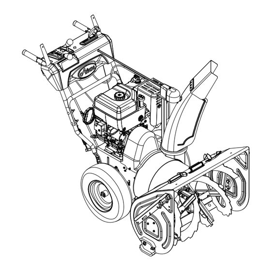
CONTROLS AND FEATURES Figure 9 1. Skid Shoes 11. Chute Rod 2. Clean-Out Tool 12. Handlebar Hardware 3. Remote Discharge Chute Deflector 13. Heated Handles 4. Belt Cover 14. Drift Cutters 5. Headlight 15. Height Adjuster Trigger (926324) 6. Auger 16. - Page 15 17, 18 Figure 10 1. Oil Drain 12. Speed Selector 2. Fuel Shut-Off Valve 13. Traction Drive Clutch Lever 3. Primer Bulb 14. Deflector Remote Control 4. Recoil Starter Handle 15. Chute Control 5. Throttle 16. Muffler Guard 6. Choke Control Knob 17.
-
Page 16: Operation
OPERATION Attachment Clutch – WARNING: AVOID INJURY. Read Right Hand Lever and understand the entire Safety section before proceeding. Squeeze Attachment Clutch Lever against handlebar (1) to WARNING: To avoid injury to hands engage attachment. and feet, always disengage Release both clutch clutches, shut off engine, and wait levers (2) to disengage for all movement to stop before... - Page 17 Speed Selector Snow Clean-Out Tool Position the Speed Selector in (Figure 11) the appropriate speed notch to control forward and reverse WARNING: Hand contact with the travel. rotating impeller is the most Forward: common cause of injury associated (6) Fastest with snow throwers.
-
Page 18: Heated Handles
Drift Cutters (Figure 13) Drift cutters break up snow drifts that are taller than the auger housing and direct the snow into the auger. Store the drift cutters on the auger housing when not in use. Install them as shown below so they are taller than the snow to be cleared. -
Page 19: Filling Fuel Tank
IMPORTANT: Excessively oxygenated or Normal reformulated fuels (fuels blended with alcohols or ethers) can damage the fuel system or cause performance problems. If any undesirable operating problems occur, use a gasoline with a lower percentage of alcohol or ether. Add Fuel Stabilizer to Extend Fuel Storage Life IMPORTANT: Fuel stabilizer is recommended Transport... - Page 20 PRE-START STARTING AND SHUT OFF 1. Frozen Impeller WARNING: FAILURE TO FOLLOW IMPORTANT: Before starting engine, check INSTRUCTIONS could result in impeller to be sure it is not frozen. personal injury and/or damage to To check impeller: unit. DO NOT attempt to start your 1.
- Page 21 IMPORTANT: Use an extension cord that is capable of handling current requirements. 1. Release Traction Drive Clutch Lever and See your Ariens dealer for recommended allow unit to come to a complete stop. extension cord. 2. Run Impeller a few minutes after use to 3.
-
Page 22: Maintenance
MAINTENANCE MAINTENANCE SCHEDULE Ariens Dealers will provide any service or adjustments which may be required to keep The chart below shows the recommended your unit operating at peak efficiency. Should maintenance schedule that should be engine service be required, contact an Ariens performed on a regular basis. -
Page 23: Change Engine Oil
Adjustment on page 30. NOTICE: Inspect seal washer for wear or rubber deterioration and replace as needed. CHECK CLUTCH CABLE IMPORTANT: Use only Ariens L3 synthetic ADJUSTMENT severe duty gear lube (Part Number 00068800). Use of other lubricants will void Make sure the attachment clutch and traction unit warranty. - Page 24 Shear get on friction disc, friction plate or belts. Bolts on page 26. Apply grease at the grease NOTICE: Apply Ariens Hi-Temp Grease or zerks and then turn the auger assemblies on equivalent to the lubrication fittings. See the auger shaft.
- Page 25 Clean Battery (926513, 516) 4. Replace the cover plate and secure in position with the two screws removed in step 1. WARNING: AVOID INJURY. Read NOTICE: Make sure the wire harness does and understand the entire Safety not get pinched between the cover plate and section before proceeding.
-
Page 26: Service And Adjustments
SHEAR BOLTS WARNING: AVOID INJURY. Read (Figure 23) and understand the entire Safety IMPORTANT: Use only Ariens OEM shear section before proceeding. bolts for replacement. Use of any other type of shear bolt may result in severe damage to SCRAPER BLADE unit. - Page 27 HANDLEBAR HEIGHT REMOTE DEFLECTOR CONTROL (Figure 24) (Figure 25) Deflector must stay in selected position while CAUTION: AVOID INJURY. Adjust throwing snow. the attachment clutch, speed If deflector does not stay in set position: selector and traction clutch after 1. Tighten nut beneath control panel to changing the handlebar height.
-
Page 28: Attachment Clutch/Brake Adjustment
DISCHARGE CHUTE CONTROL d. Stop unit. e. Shift speed selector into first (Figure 26) reverse speed. If chute does not stay in position while f. Engage the traction clutch. Unit throwing snow or if chute does not rotate should move backward. freely, adjust the cable under the gear cover g. - Page 29 Check Attachment Idler Arm Roller Clearance (Figure 30) NOTICE: It will be difficult to check the measurement inside the frame. Use a 12,7 mm minimum spacer as a gauge to check the clearance between the roller and the frame. 1. Place the unit into the service position. Remove the bottom cover.
- Page 30 Check Attachment Brake Check belt finger clearance here. With the (Figure 31) attachment clutch engaged, there should 1. With the clutch lever disengaged, brake be less than 3 mm clearance between the pad must contact attachment belts. With belts and the belt finger. The belt finger clutch lever engaged, brake pad must be should not touch the belts.
- Page 31 ATTACHMENT DRIVE BELTS REPLACEMENT (Figure 33) Remove Old Attachment Drive Belts 1. Shut off engine, remove key, disconnect spark plug wire and allow unit to cool completely. 2. Loosen hardware securing belt cover to unit (Figure 33). NOTICE: Do NOT completely remove the hardware from unit.
- Page 32 TRACTION DRIVE BELT FRICTION DISC REPLACEMENT REPLACEMENT (Figure 35) 1. Place unit into service position. (Figure 34) 2. Remove bottom cover by removing six NOTICE: Replacement will be easier with hex bolts. housing and frame tipped apart and bottom cover off. 3.
- Page 33 BATTERY (926513, 516) Charging 1. Place unit on a level surface and shut off engine. 2. Disconnect negative (–) cable first, then Track positive (+) cable. Adjusters 3. Loosen wing nut and remove battery. Figure 37 Place battery on bench or other well- ventilated place.
-
Page 34: Storage
(see MAINTENANCE on page 22). Touch up all ACCESSORIES scratched painted surfaces. Remove weight from wheels by putting See your authorized Ariens dealer to add blocks under frame or axle. the additional accessories available to your Sno-Thro. FUEL SYSTEM Part No. -
Page 35: Troubleshooting
TROUBLESHOOTING PROBLEM PROBABLE CAUSE CORRECTION Engine will not 1. Fuel tank is empty. 1. Fill fuel tank (see Filling Fuel Tank on page 19). crank/start. 2. Fuel shut-off valve closed. 2. Open fuel shut-off valve. 3. Build up of dirt and residue 3. -
Page 36: Specifications
SPECIFICATIONS Model Number 926321 926324 926513 926516 Description Pro 28 Pro 28 Track Pro 32 Pro 32 Engine Engine Model Briggs & Stratton Polar Force Briggs & Briggs & 2100 Stratton Polar Stratton Polar Force 1650 Force 2100 Gross Torque* – N-m 28,5 22,37 28,5... -
Page 37: Warranty
® ® Sno-Thro , Sno-Tek Chore Performing Equipment Limited Warranty Ariens Company (Ariens) warrants to the original purchaser that Ariens, Gravely, Parker, and Countax ® ® brand chore performing equipment (including Sno-Thro and Sno-Tek equipment) purchased on or after 1/1/2013 will be free from defects in material and workmanship for the time period noted in the chart below. -
Page 38: Customer Responsibilities
Register the product immediately at the time of sale. If the dealer does not register the product, the customer must complete the product registration card in the literature package and return it to Ariens Company, or register the unit online at www.ariens.com, www.gravely.com, www.countax.com or www.parkersweeper.com. - Page 39 Exclusions – Items Not Covered by This Warranty • Parts that are not genuine Ariens, Gravely, Parker or Countax service parts are not covered by this warranty and may void the warranty. • Damages resulting from the installation or use of any part, accessory, or attachment which is not approved by the Ariens Company for use with product(s) identified herein are not covered by this warranty.
- Page 40 Ariens 655 West Ryan Street Brillion, WI 54110 920-756-4688 www.ariens.eu...
Need help?
Do you have a question about the Professional 32 - 12 Volt and is the answer not in the manual?
Questions and answers