Table of Contents
Advertisement
Comfort Systems
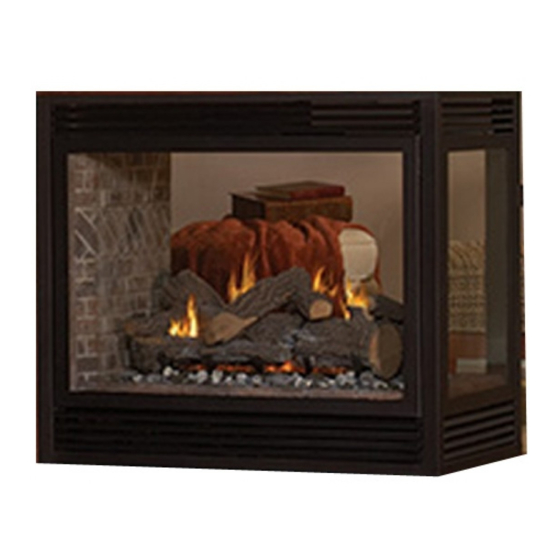
The Direct Vent Zero Clearance Gas
Fireplace Heater
Installer:
Leave this manual with the appliance.
Consumer: Retain this manual for future reference.
WARNING: If the information in these instructions
result causing property damage, personal injury
or loss of life.
vapors and liquids in the vicinity of this or any
other appliance.
— WHAT TO DO IF YOU SMELL GAS
any phone in your building.
neighbor's phone. Follow the gas supplier's
instructions.
— Installation and service must be performed by a
plier.
WARNING: If not installed, operated and maintained
in accordance with the manufacturer's instructions,
this product could expose you to substances in fuel
or from fuel combustion which can cause death or
serious illness.
INSTALLATION INSTRUCTIONS
OWNER'S MANUAL
-
AND
DIRECT VENT
GAS FIREPLACE HEATER
MODEL SERIES
DVP36PP32EN-3
DVP36PP32EP-3
DVP36SP32EN-3
DVP36SP32EP-3
GAS-FIRED
UL FILE NO. MH30033
WARNING
This appliance may be installed in an aftermarket,
permanently located, manufactured home (USA only)
or mobile home, where not prohibited by state or local
codes.
This appliance is only for use with the type of gas
indicated on the rating plate. This appliance is not
kit is used.
HOT GLASS
WILL
CAUSE BURNS.
DO NOT TOUCH
GLASS
UNTIL COOLED.
NEVER
ALLOW CHILDREN
TO TOUCH GLASS.
Page 1
Advertisement
Table of Contents

Subscribe to Our Youtube Channel
Related Manuals for Empire DVP36PP32EN-3


Summary of Contents for Empire DVP36PP32EN-3
-
Page 1: Installation Instructions
INSTALLATION INSTRUCTIONS OWNER’S MANUAL Comfort Systems DIRECT VENT The Direct Vent Zero Clearance Gas Fireplace Heater GAS FIREPLACE HEATER MODEL SERIES DVP36PP32EN-3 DVP36PP32EP-3 DVP36SP32EN-3 DVP36SP32EP-3 GAS-FIRED Installer: Leave this manual with the appliance. UL FILE NO. MH30033 Consumer: Retain this manual for future reference. -
Page 2: Table Of Contents
TABLE OF CONTENTS Section Page Carton Contents ............................3 Hardware Package ............................3 Important Safety Information ........................4 Safety Information for Users of LP Gas......................5 Requirements for Massachusetts ......................... 6 Introduction..............................7 ............................... 8 Fireplace Dimensions ........................... 9 Clearances ..............................10 Optional EMPT Series Mantel Installation - Peninsula Models Only ............ -
Page 3: Carton Contents
CARTON CONTENTS Additional Parts for Peninsula Models Only: Fireplace Assembly Canopy, End* Installation Package Canopy, Right* 3/8" x 12" Flexline Canopy, Left* Rockwool Packet End Shield* Installation Instructions Canopy Corner Tie* Serial Number Tag *Note: Installation required when using EMPT Recepticle, 3-Prong series Peninsula Mantle Warranty Card... -
Page 4: Important Safety Information
If the glass is cracked or damaged in any way, it should be replaced only with a complete glass frame assembly from Empire. See parts list on Pages 53 through 55 for ordering. Installation and repair should be done by a QUALIFIED SERVICE PERSON. -
Page 5: Safety Information For Users Of Lp Gas
SAFETY INFORMATION FOR USERS OF LP GAS by point with the members of your household. Someday and explosions. In its natural state, propane is odorless and when there may not be a minute to lose, everyone’s safety colorless. You may not know all the following safety precau- will depend on knowing exactly what to do. -
Page 6: Requirements For Massachusetts
REQUIREMENTS FOR MASSACHUSETTS For all side wall horizontally vented gas fueled equipment installed in every dwelling, building or structure used in whole or in part for permanently mounted to the exterior of the building at a residential purposes, including those owned or operated by the minimum height of eight (8) feet above grade directly in line Commonwealth and where the side wall exhaust vent termination with the exhaust vent terminal for the horizontally vented... -
Page 7: Introduction
INTRODUCTION Instructions to Installer Warning: ANY CHANGE TO THIS FIREPLACE OR ITS 1. Installer must leave instruction manual with owner after CONTROLS CAN BE DANGEROUS. installation. or carbon monoxide poisoning. 3. Installer should show owner how to start and operate the Any alteration of the original design, installed other than as shown in these instructions or use with a type of gas not all combustion air being siphoned from the outside of the building... - Page 8 SPECIFICATIONS DVP36(SP,PP) Nat Models Remote Control Description Input Btu/hr Maximum 35,000 Options & Accessories Btu/hr Minimum (millivolt only) 24,000 FRBC Millivolt Battery Remote ON/OFF KWH (Maximum) 10.15 FRBTC Millivolt Battery Remote T-Stat (Minimum) 6.96 FRBTP Millivolt Battery Remote with Thermostat Millivolt Wireless Wall Thermostat Air Shutter Opening 5/16"...
-
Page 9: Fireplace Dimensions
FIREPLACE DIMENSIONS HORIZONTAL VENT CONNECTION SEE THRU PENINSULA 31 7/8 17 ½ 32 ½ 32 ½ Figure 1 MODEL DVP36SP32E DVP36PP32E 34 3/4” 34 3/4” 39" 39" 24” 24” 22" 22" 36” 36” 29 1/4” 32 5/8” 22” 22” 41 1/8” 41 1/8”... -
Page 10: Clearances
CLEARANCES Clearance to Combustibles Air Drop (End) 1/2" (12.7 mm) Side 1/2" (12.7 mm) Floor 0" (0 mm) Top Stand-off 0" (0 mm) Top Framing Edge 6 3/8" (161.7 mm) SEE MANTLE CHART FOR MAXIMUM MANTLE DEPTH 42 ” 1 3/4” MIN. 2”... -
Page 11: Optional Empt Series Mantel Installation - Peninsula Models Only
OPTIONAL EMPT SERIES MANTLE INSTALLATION - PENINSULA MODELS ONLY the Rear Mantel Corner Bracket. Align the holes in the canopy and End Shield. These additional parts must be installed on the with the corner bracket and loosely install a #10 x 1/2" Hex Head screw to retain. -
Page 12: Locating Fireplace
LOCATING FIREPLACE Note:** Island (C) and Room Divider (D) installation is possible as long as the horizontal portion of the vent system (H) does not exceed 20 feet with a minimum vertical run of 8 feet. See details in Venting Section. *When you install your Direct Vent Fireplace, a minimum of 1 3/4 inches clearance must be maintained from the perpendicular wall and from the opening would be 2 1/2 inches. -
Page 13: Gas Supply
GAS SUPPLY The gas pipeline can be brought in through the right or left side of Installing a New Main Gas Cock the appliance. Consult the current National Fuel Gas Code, ANSI Each appliance should have its own manual gas cock. Z223.1 CAN/CGA-B149 (.1 or .2) installation code. -
Page 14: Rear Vent Conversion
REAR VENT CONVERSION HORIZONTAL VENTING VERTICAL VENTING Note: It is recommended that the flue cover plate tab be pulled outward prior to removal. INLET VENT COVER PLATE INLET VENT COLLAR FLUE COVER PLATE This will ensure that the plate is not accidentally dropped FLUE OUTLET COLLAR inside the rear air chamber. -
Page 15: Planning Installation
PLANNING INSTALLATION determine where the unit is to be installed and whether optional installed on a metal or wood panel extending the full width accessories are desired. Gas supply piping should also be planned and depth of the unit. at this time. A gas shutoff must be installed in this line. At this point, you should have decided what components to include has not been done, stop and consult your dealer for assistance 2. - Page 16 FIREPLACE INSTALLATION INSTRUCTIONS (continued) Locating Fireplace framed opening and secure to framing. Different hole locations can 3/4". Secure the brackets with screws provided using two (2) per framing bracket. See Figure 13. at least one (1) nail or screw per bracket to secure in place. IMPORTANT! FIREPLACE OPENING prior to securing to the framed openings.
-
Page 17: Installation
INSTALLATION Attention: Flush Mount Mantel Installation - See-through Models Only base. (Figure 15) Attention: If a base or mantel is not used and the appliance is installed directly on carpeting, tile or other combustible material panel extending the full width and depth of the appliance. The hex-head screws supplied in hardware package to attach nailing vertical dimension must be adjusted when a metal or wood panel is placed beneath the appliance. - Page 18 Combustible Surround Installation Vent Pipe Clearance Note: Maintain one inch (1") of clearance around vertical vent pipe. See Figure 18. For horizontal vent, maintain a minimum 1" clearance to the bottom and sides of the vent, and 3" clearance to combustibles above the vent pipe.
-
Page 19: Installation
INSTALLATION (continued) HORIZONTAL ONLY, STRAIGHT OUT THE BACK “A” PIPE LENGTH VENT CAP WALL FIRESTOP/ THIMBLE “B” "A" "B" 6" 5 1/8" to 6 1/2" 9" 8 1/8" to 9 1/2" 12" 11 1/8" to 12 1/2" Figure 20 VERTICAL, 90° ELBOW TO HORIZONTAL OUT THE WALL “A”... -
Page 20: Venting Fireplace - Top
VENTING FIREPLACE - TOP Venting Graph (Dimensions in Feet) To Use the Vent Graph (Figure 22) 1. Determine the height of the center of the horizontal vent pipe. Using this dimension on the Sidewall Vent TOP EXIT - VERTICAL AND HORIZONTAL TERMINATION Graph, locate the point it intersects with the slanted (DIMENSIONS IN FEET) graph line. - Page 21 VENTING FIREPLACE - TOP (continued) Below Grade Installation When it is not possible to meet the required vent terminal clearances of 12" (305mm) above grade level, a snorkel kit is recommended. See page 38. It allows installation depth down to 7" (178mm) below grade level.
- Page 22 10” (254mm) VENT CAP 11” SEE VENT CHART (279mm) FOR PERMISSIBLE “H” AND “V” DIMENSIONS 1 FOOT VERTICAL PIPE REQUIRED (MINIMUM) 9” (229 MM) MINIMUM NOTE: 1 FOOT SECTION (MIN.) OF VERTICAL VENT REQUIRED WHEN USING HORIZONTAL CENTER OF ELBOW TERMINATION OFF TOP.
-
Page 23: Dvvk-4Fv Direct Vent Termination Kit
DVVK-4FV DIRECT VENT TERMINATION KIT Installation Instructions starting the installation. This vent kit may be installed as an OEM installation in a manufactured home (USA only) or mobile home and must be installed in accordance with the manufacturer’s instructions and the manufactured home construction and safety standard, Title 24 CFR, Part 3280 or Standard for Installation in Mobile Homes, CAN/CSA Z240 MH. - Page 24 PRE-INSTALLATION INFORMATION: Items Required For Installation: Tools Building Supplies Phillips Screwdriver Framing Materials Hammer Wall Finishing Materials Saw and/or saber saw Caulking Material (Noncombustible) Level Support Strap supplies Measuring Tape Electric Drill and Bits Pliers Square Tin Snips Before You Start: components out, then trim off what will not be needed.
- Page 25 DVVK-4FV DIRECT VENT TERMINATION KIT (continued) Step-By-Step Installation For Flex DV Kit Unpack vent components and check all items for shipping Next, determine the location for the cutout in the roof opening. damage. This opening must be large enough to provide a minimum 1” For this venting system to operate as designed it is dependent air space clearance from the vertical vent pipe to any combus- on the use of all parts and procedures detailed in these in-...
- Page 26 DVVK-4FV DIRECT VENT TERMINATION KIT (continued) 13. Now the pre-assembled vent system may be carried to the roof, then lowered through the roof cutout opening (see step gether. First, apply a generous bead of silicone sealant to 14. Secure the roof support assembly to the roof sheathing with at least (4) nails/screws through each support bracket.
- Page 27 DVVK-4FV DIRECT VENT TERMINATION KIT (continued) 21. An additional storm collar band is provided in kit that may be diameter adapter collar has been installed per step 3. Apply a used as an attic insulation shield. The collar can be installed thimble.
- Page 28 DVVK-4FV DIRECT VENT TERMINATION KIT (continued) VERTICAL TERMINATION STORM COLLAR 4’ LONG RIGID PIPE ROOF FLASHING ADJUSTABLE ROOF JACK ASSEMBLY ROOF EXTERIOR CLEARANCE TO COMBUSTIBLES REQUIRED FROM VENT PIPE CLAMPS AT FLUE & INLET VENT CONNECTIONS ADJUSTABLE STORM COLLAR (USE TO FIRESTOP/THIMBLE KEEP INSULATION OUT OF ASSEMBLY...
-
Page 29: Dvvk-4Fv Direct Vent Termination Kit
DVVK-4FV DIRECT VENT TERMINATION KIT (continued) Vertical Flex Termination Kit Item Quantity Number Item Description Repair Part No. Supplied 4”/7” Vertical Termination Cap MF100038 Roof Support Kit MF100503 2 Ply Alum Flex 4” Diameter by 6 ft. MF04ALA2F006 2 Ply Alum Flex 7” Diameter by 6 ft. MF07ALA2F006 4”/7”... -
Page 30: Examples - Top Vent Run
EXAMPLES - TOP VENT RUN 24” 24” MINIMUM CLEARANCE TO COMBUSTIBLES Example H2 3ft, H3 1ft = 4ft (90° + 90° + 90°) = 6ft V1 = 21ft H = 10ft V = 21ft Figure 37 Ex a m p l e H2 = 2f t 2 - (90°+ 90°... -
Page 31: Venting Fireplace - Rear
VENTING FIREPLACE - REAR Venting Graph (Dimensions in Feet) To Use the Vent Graph (Figure 39) 1. Determine the height of the center of the REAR EXIT - VERTICAL AND HORIZONTAL TERMINATION horizontal vent pipe. Using this dimension on the (DIMENSIONS IN FEET) Sidewall Vent Graph, locate the point it intersects with the slanted graph line. -
Page 32: Examples - Rear Vent Run
EXAMPLES - REAR VENT RUN Model Maximum Pipe Length H1 DVP36(SP,PP) 18" H1 = 18” MAX. Figure 42 Figure 40 Model Maximum Pipe Length H1 DVP36(SP,PP) 18" Figure 43 H1 = 18 i n c h e s m a x Figure 41 Page 32 30786-0-0712... -
Page 33: Termination Clearances
TERMINATION CLEARANCES Termination clearance for buildings with combustible and noncombustible exteriors. Figure 44 Vertical Sidewall Installations Important! Minimum clearance between vent pipes and combustible materials is three (3") (76mm) on top, and (1") (25mm) on bottom and sides. Important! When vent termination exits through foundation less than 20" below siding outcrop, the vent pipe must extend outward so that Information on Various Venting Routes and Components Important: The graph showing the relationship between vertical and horizontal side wall venting will help to determine the various vent lengths... -
Page 34: Vent Clearances
VENT CLEARANCES Figure 45 *Clearance above grade, veranda, porch, deck or balcony clearance to non-mechanical air supply inlet to building or [*12 inches (30cm) minimum] the combustion air inlet to any other appliance [*12 inches clearance to window or door that may be opened [*12 inches (30cm) minimum for appliances <... - Page 35 45° ELBOW TWO 90° ELBOWS) ROOF FLASHING 90° ELBOW Special venting components (Simpson Duravent) See Empire Comfort Systems Retail Price List for Simpson Duravent part numbers and pricing. CEILING FIRESTOP Special DV Vent Kits WALL STRAP Available from Empire Comfort Systems, Inc. dealers.
-
Page 36: Framing And Finishing
FRAMING AND FINISHING Installing Support Brackets (Figure 47) A horizontal pipe support MUST BE used for each 3 feet of horizontal run. The pipe supports should be placed around the pipe and nailed in place to framing members. There MUST BE a 3 inch clearance to combustibles above 6 5/8 inch diameter pipe and elbows and 1 inch clearance on both sides and bottom of 6 5/8 inch pipe to 10”... -
Page 37: Framing And Finishing
FRAMING AND FINISHING (continued) Figure 49 Figure 51 Figure 50 30786-0-0712 Page 37... -
Page 38: Horizontal Termination
HORIZONTAL TERMINATION NOTE: the exterior of the building. Adjust the termination cap to SNORKEL WARNING: Termination cap must be positioned so that arrow is pointing up. Attach the termination cap with the four wood screws provided. Before attachment of the termination, run a bead of silicone sealant rated above 250°F on its outside edge too, so as to make a seal to the exterior wall. -
Page 39: Dvvk-4Re Vent Kit Installation Instructions
NOTE: If installing onto wood, lap, or vinyl siding, the vinyl siding kit should be used (sold separately, part number DV-822). 9” The vinyl siding vent kit, DV-822, is available from Empire Comfort Figure 54 Systems, Inc. The depth is 3” (76mm), which enables the vent cap to be extended away from vinyl siding or projections. - Page 40 DVVK-4RE VENT KIT INSTALLATION INSTRUCTIONS (continued) VINYL SIDING KIT DV822 OUTSIDE MOUNTING PLATE tube 2 1/2” (64mm) beyond the vinyl siding kit or wall. See Figure 57. tape gasket needs to be used. 9. Mark or wrap tape completely around the tubes at the marked points to help in making a true cut.
-
Page 41: Dvvk-4Re Vent Kit Installation Instructions
DVVK-4RE VENT KIT INSTALLATION INSTRUCTIONS (continued) Follow correct option according to venting method. Connecting to Rigid Vent System Connecting Directly to Fireplace venting system (and not directly to the back of the unit), then do not use the gasket provided. High temperature sealant should be the unit (no rigid venting system is being used), then the gasket (if tube was cut, it is recommended to use cut end) and to the in- Peel the paper off the self-adhesive gasket and then wrap it around... -
Page 42: Dvvk-4F Flex Vent Instructions
DVVK-4F FLEX VENT INSTRUCTIONS The DVVK-4F FLEX VENT KIT includes the following components: pipe) a minimum rise of 2". Vent connections should overlap a minimum of 1" for proper sealing. Always follow the general venting requirements for vent terminal location, vent lengths, and clearance to combustible materials. INSTALLATION If the venting is to long, trim off any excess vent before Unpack vent components and check that all items are... -
Page 43: Vertical Termination
VERTICAL TERMINATION Locate and mark the center point of the venting pipe. Using a nail When terminating the vent cap near an exterior wall or overhang, on the underside of the roof and drive this nail through this center maintain minimum clearances as shown in Figure 60. point. -
Page 44: Vertical Termination
10 feet and 40 feet. To maintain the yellow 45° use with 6 5/8" diameter vent systems, or the VIB7A for use with 8’ (2.44M) MAXIMUM 7" diameter vent systems. These are available from your Empire Comfort Systems, Inc. distributor or dealer. TYPICAL ROOF SUPPORT FLEX VENT 35’... -
Page 45: Placement Of Glowing Embers
PLACEMENT OF GLOWING EMBERS Placement of the glowing embers (rockwool) is very individual and light coverage of the areas indicated will provide your best effects. We recommend separation of the rockwool by hand and to make Place just enough embers on the burner to obtain the glow and a Do not place rockwool over large port areas. -
Page 46: Operation Instructions/Flame Appearance
OPERATION INSTRUCTIONS/FLAME APPEARANCE Before you begin: Do not handle the logs with your bare hands! The initial break-in operation should be 5 to 10 minutes on (at the Always wear gloves to prevent skin irritation. After handling logs, highest setting) then let cool for 10 to 15 minutes. Repeat this On/ wash your hands gently with soap and water. -
Page 47: Operating Instructions
OPERATING INSTRUCTIONS 750 Millivolt System The standing pilot (750 millivolt system) is a continuous burning pilot. Subsequent lightings of the appliance will not require such purging The pilot remains ON even when the main burner is OFF. if the gas valve is not turned to “OFF.” When you ignite the pilot, the thermopile produces millivolts (electrical Pilot Flame (Figure 65) current) which energizes the magnet in the gas valve. -
Page 48: Operating Instructions
OPERATING INSTRUCTIONS (continued) STANDING PILOT OPERATING INSTRUCTIONS Reassembly and Resealing Gas Accumulation Relief System REMOTE/OFF/ON Switch Glass Frame Assembly and Combustion Chamber REMOTE/OFF/ON switch. A Whenever the glass frame assembly is pivoted open by a delayed wire harness is attached to the REMOTE/OFF/ON switch. The ignition in the main burner, the glass frame assembly gaskets and red, black and green (wires) female push-ons attach to the REMOTE/OFF/ON switch. -
Page 49: Standing Pilot Wiring Diagram
STANDING PILOT WIRING DIAGRAM (OPTIONAL) THERMOSTAT (OPTIONAL) WALL SWITCH Figure 66 30786-0-0712 Page 49... -
Page 50: Standing Pilot Lighting Instructions
STANDING PILOT LIGHTING INSTRUCTIONS FOR YOUR SAFETY READ BEFORE LIGHTING WARNING: property damage, personal injury or loss of life. A. This appliance has a pilot which must be lighted by hand. When lighting the pilot, follow these instructions exactly. ment. B. -
Page 51: Standing Pilot Troubleshooting
STANDING PILOT TROUBLESHOOTING With proper installation and maintenance, your new Direct Vent Gas Fireplace will provide years of trouble-free service person in the diagnosis of problems and the corrective action to be taken. 1. Spark ignitor will not light pilot after repeated triggering of c. -
Page 52: Maintenance And Service
MAINTENANCE AND SERVICE WARNING: Do not use abrasive cleaners on glass. Do not PLEASE NOTE attempt to clean glass when glass is hot. It is normal for appliances fabricated of steel to give off some expansion and/or contraction noise during the start Glass Removal and Replacement (Figure 67) up or cool down cycle. -
Page 53: Parts List
PARTS LIST PART NO. PART NO. INDEX INDEX DESCRIPTION DESCRIPTION DVP36SP DVP36PP DVP36SP DVP36PP MALE 5/16 X 3/8 NPT 24316 24316 FIREPLACE ASSEMBLY R2423 R2423 CONNECTOR UPPER LOUVER 18807 18807 R7577 R7577 VALVE - NAT ASSEMBLY R7578 R7578 VALVE - LP GLASS FRAME 24307 24307... -
Page 54: Dvp36Sp Parts View
DVP36SP PARTS VIEW Page 54 30786-0-0712... -
Page 55: Dvp36Pp Parts View
DVP36PP PARTS VIEW 30786-0-0712 Page 55... -
Page 56: Wiring Instructions For Installing A Dual Switch / Receptacle
WIRING INSTRUCTIONS FOR INSTALLING A DUAL SWITCH / RECEPTACLE In order to install both the optional Blower and Accent Light acces- CAUTION: ALL WIRING SHOULD BE DONE BY A QUALIFIED sories, it will be necessary to install the junction box so that the ELECTRICIAN AND SHALL BE IN COMPLIANCE WITH ALL Duplex Receptacle wiring is split. -
Page 57: Accent Lamp
ACCENT LAMP Your Direct Vent Gas Fireplace comes equipped with an "Accent COVER Lamp." The light has been pre-wired and is controlled from the Rheostat. If in the event the lamp or lens needs to be replaced, follow the instructions below: Unplug the Accent Lamp from the junction box inside the Remove the four screws that secure the lens frame. -
Page 58: Optional Fbb5 Blower Installation Instructions
OPTIONAL FBB5 BLOWER INSTALLATION INSTRUCTIONS To install the blower kit or access the junction box, remove lower Attention: Install blower assembly before connecting gas in- let supply line. A factory included junction box is located in the lower compartment Wiring The appliance, when installed, must be electrically grounded in accordance with local codes or, in the absence of local codes, outer wrap with the clamp provided. - Page 59 OPTIONAL BLOWER INSTALLATION INSTRUCTIONS (continued) 10. Replace louver(s). 11. This completes the installation of the optional FBB5 Blower kit Note: On peninsula models, the blower must be installed at accessory. the end which has the brick panel installed. Position blower assembly so that you align the notch on back of blower as- Note: This blower is equipped with a heat activated fan control sembly with the center screw on side/end panel, then push...
- Page 60 OPTIONAL BLOWER INSTALLATION INSTRUCTIONS (continued) Blower Motor Wiring The blower motor does not have oiling holes. Do not attempt to oil The appliance, when installed, must be electrically grounded in the blower motor. accordance with local codes or, in the absence of local codes, with the National Electrical Code, ANSI/NFPA 70, if an external electrical Blower Wheels source is utilized.
-
Page 61: Accessories
ACCESSORIES The following accessory parts can be obtained from your Empire Comfort Systems dealer. If you need additional information beyond what your dealer can furnish, contact Empire Comfort Systems Inc., Nine Eighteen Freeburg Ave., Belleville, Illinois 62220-2623. Accessory Description Model Numbers... -
Page 62: Master Parts Distributor List
MASTER PARTS DISTRIBUTOR LIST To Order Parts Under Warranty, please contact your local Empire dealer. See the dealer locator at www.empirecomfort. com. To provide warranty service, your dealer will need your name and address, purchase date and serial number, and the nature of the problem with the unit. -
Page 63: Appliance Service History
APPLIANCE SERVICE HISTORY Date Dealer Name Service Technician Name Service Performed/Notes 30786-0-0712 Page 63... - Page 64 Empire Comfort Systems Inc. 918 Freeburg Ave. Belleville, IL 62220 If you have a general question about our products, please e-mail us at info@empirecomfort.com. If you have a service or repair question, please contact your dealer. Comfort Systems www.empirecomfort.com Page 64...
Need help?
Do you have a question about the DVP36PP32EN-3 and is the answer not in the manual?
Questions and answers