Table of Contents
Advertisement
Quick Links
INSTALLER:
Leave this manual with the appliance.
CONSUMER:
Retain this manual for future reference.
WARNING
FIRE OR EXPLOSION HAZARD
Failure to follow safety warnings exactly
could result in serious injury, death or
property damage.
— Do not store or use gasoline or other
flammable vapors and liquids in the
vicinity of this or any other appliance.
— WHAT TO DO IF YOU SMELL GAS
•
Do not try to light any appliance.
•
Do not touch any electrical switch;
do not use any phone in your building.
•
Leave the building immediately.
•
Immediately call your gas supplier
from a neighbor's phone. Follow
the gas supplier's instructions.
•
If you cannot reach your gas
supplier, call the fire department.
— Installation and service must be
performed by a qualified installer,
service agency or the gas supplier.
WARNING
A barrier designed to reduce the risk of burns from the
hot viewing glass is provided with this appliance and shall
be installed for the protection of children and other at-risk
individuals.
INSTALLATION INSTRUCTIONS
HOT GLASS
WILL
CAUSE BURNS.
DO NOT TOUCH
GLASS
UNTIL COOLED.
NEVER
ALLOW CHILDREN
TO TOUCH GLASS.
DIRECT VENT ZERO
CLEARANCE GAS FIREPLACE
HEATER SERIES MODELS:
MILLIVOLT (MV)
DVCP42BP30K(N,P)-4
INTERMITTENT PILOT (IP)
DVCP42BP70K(N,P)-4
This appliance may be installed in an aftermarket,
permanently located, manufactured home (USA
only) or mobile home, where not prohibited by
state or local codes.
This appliance is only for use with the type of gas
indicated on the rating plate. This appliance is
not convertible for use with other gases, unless
a certified kit is used.
GAS-FIRED
UL FILe No. mH30033
This fireplace is design
certified in accordance
with American National
Standard/CSA Standard
ANSI Z21.88/CSA 2.33
and by Underwriters
Laboratories as a Direct
Vent Gas Fireplace
Heater and shall be
installed according to
these instructions.
Page 1
Advertisement
Table of Contents
Troubleshooting

Related Manuals for Empire MILLIVOLT DVCP42BP30KN-4


Summary of Contents for Empire MILLIVOLT DVCP42BP30KN-4
- Page 1 INSTALLATION INSTRUCTIONS INSTALLER: DIRECT VENT ZERO Leave this manual with the appliance. CLEARANCE GAS FIREPLACE CONSUMER: HEATER SERIES MODELS: Retain this manual for future reference. MILLIVOLT (MV) DVCP42BP30K(N,P)-4 WARNING INTERMITTENT PILOT (IP) FIRE OR EXPLOSION HAZARD DVCP42BP70K(N,P)-4 Failure to follow safety warnings exactly could result in serious injury, death or property damage.
-
Page 2: Table Of Contents
TABLE OF CONTENTS SECTION PAGE ATTeNTIoN INSTALLeR ............................. 3 BeFoRe YoU START .............................. 4-5 CARToN CoNTeNTS ..............................6 INTRoDUCTIoN ................................7 HomeoWNeR ReFeReNCe INFoRmATIoN ......................7 SPeCIFICATIoNS ................................ 8 ACCeSSoRIeS ................................9 FIRePLACe DImeNSIoNS ............................10 FBB10 BLoWeR KIT INSTALLATIoN (oPTIoNAL) .................... 11-13 CLeARANCeS ................................ -
Page 3: Attention Installer
____________________ fireplace and given to party responsible for use and operation ..........____________________ Provide homeowner with “Scratch & Sniff” odor card ............Empire recommends the following: • Keep this checklist visible on the fireplace until the installation is complete. •... -
Page 4: Before You Start
TV manufacturers recommend against placing their products near a heat source. Indicates a hazardous situation which, if not avoided, will If you install a television above this fireplace, empire Comfort result in death or serious injury. Systems accepts no responsibility for damage or injuries. Follow the television manufacturer’s installation instructions, including... - Page 5 BEFORE YOU START (CONT’D) Preparation Accessories This fireplace and its components are safe when installed most accessories install much more easily before fitting the in accordance with this manual. Report any parts damaged fireplace to the opening. in shipment to your dealer. Do not install the fireplace with For example, it takes just 10-15 minutes to install the blower side damaged, incomplete or substitute parts.
-
Page 6: Carton Contents
CARTON CONTENTS NOTICE: Items not shown to scale. QUANTITY SUPPLIED INDEX DESCRIPTION DVCP42BP3 DVCP42BP7 NUMBER SERIES SERIES Rock Wool Receptacle Cover Receptacle Flue Restrictor Assembly - (See Page 30) 10 X 1/2 Phillips Screw #8 X 1 Self-Drilling Drywall Screw AA Battery AC Adaptor Backer Stud... -
Page 7: Introduction
INTRODUCTION The information in this manual pertains to all models and gas Fireplace Certification control systems unless otherwise noted. This fireplace is design certified in accordance with American National Standard/CSA Standard ANSI Z21.88/CSA 2.33 and by Instructions to Installer Underwriters Laboratories as a Direct Vent Gas Fireplace Heater Leave this manual with homeowner. -
Page 8: Specifications
SPECIFICATIONS DVCP42NAT DVCP42LP Input BTU/Hr maximum 28,500 26,500 Input BTU/Hr minimum (millivolt only) 21,000 22,000 KWH (maximum) 8.35 7.77 KWH (minimum) 6.15 6.45 orifice 1.55mm Air Shutter opening 1/8-in Full open Gas Inlet Shut-off Valve (Pipe) 1/2 NPT 1/2 NPT NOTICE: Air shutters are factory set for typical venting. -
Page 9: Accessories
Lighting Kit, 120 V REQUIRED This unit requires Ceramic Fiber Logs to complete the fireplace interior. Contact your empire Comfort Systems Dealer (See Page 58) for further information. Do not operate the fireplace without the Ceramic Fiber Logs installed. 41354-0-0120... -
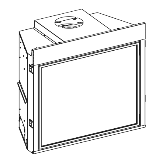
Page 10: Fireplace Dimensions
FIREPLACE DIMENSIONS TOP VIEW LEFT VIEW RIGHT VIEW FRONT VIEW GAS LINE ACCESS GAS LINE ACCESS TOP STANDOFF VENT COLLAR NAILING FLANGES BARRIER SCREEN ASSEMBLY & GLASS FRAME ASSEMBLY SIDE STANDOFF GAS CONTROL AND SWITCHES INSIDE RATING PLATE AND GAS LINE LABELS INSIDE ACCESS DVCP42... -
Page 11: Fbb10 Blower Kit Installation (Optional)
FBB10 BLOWER KIT INSTALLATION (OPTIONAL) BEFORE FIREPLACE IS INSTALLED IN WALL AFTER FIREPLACE IS INSTALLED IN WALL NOTICE: Do not handle barrier screen or door with your bare With power turned off, remove plate and four screws from left panel. See Figure 1. hands! (Always Wear Gloves) Turn off power and gas. - Page 12 FBB10 BLOWER KIT INSTALLATION (OPTIONAL) (CONT’D) Remove log set and decorative media. Remove brackets Remove the four screws securing burner and slide to right and liners if installed. Retain bracket and screws for then lift burner off. Retain burner and screws for reassembly. reassembly.
- Page 13 FBB10 BLOWER KIT INSTALLATION (OPTIONAL) (CONT’D) 10. Install blower through firebox cutout. See Figure 13. 21. Turn on power. 22. Reinstall the glass frame removed in steps 2 and 3. See Figures 5 and 6. 23. Replace barrier screen removed in step 1. See Figure 4. BLOWER ASSEMBLY PARTS LIST Figure 13 Index...
-
Page 14: Clearances
CLEARANCES Mantel Chart CLEARANCE TO COMBUSTIBLES Dimensions (Inches) Back Side Floor Top Framing edge See Below SEE MANTLE CHART FOR MAXIMUM MANTEL DEPTH 2" x 4" HEADER FINISHED WALL (COMBUSTIBLE) FIREPLACE OPENING 24” MINIMUM TO SEE MANTEL CHART CHASE TOP FOR MINIMUM HEIGHT 9”... -
Page 15: Termination Clearances
Clearances are to heat resistant material (i.e. wood, metal). This Important! When vent termination exits through foundation less does not include vinyl. empire Comfort Systems Inc. will not be held than 20 inches (508 millimeter) below siding outcrop, the vent... -
Page 16: Vent Terminal Clearances
Clearances are to heat resistant material (i.e. wood, metal). This of the following shall be indicated: does not include vinyl. empire Comfort Systems Inc. will not be Clearance in accordance with local installation codes and the requirements of the held responsible for heat damage caused from terminating under gas supplier. -
Page 17: Gas Supply
GAS SUPPLY The gas pipeline can be brought in through the right or left side of The gas lines must be checked for leaks by the installer. This should the appliance. Consult the current National Fuel Gas Code, ANSI be done with a soap solution watching for bubbles on all exposed Z223.1 CAN/CGA-B149 (.1 or .2) installation code. -
Page 18: Safety Information For Users Of Propane Gas
SAFETY INFORMATION FOR USERS OF PROPANE GAS Propane is flammable and can cause fires and explosions. Propane Gas may stratify in a closed area, and the odor In its natural state, propane is odorless and colorless. You intensity could vary at different levels. Because it is heavier may not know all the following safety precautions which than air, there may be more odor at lower levels. -
Page 19: Locating Fireplace
LOCATING FIREPLACE NOTICE: Island and room divider installation is possible as long as the horizontal portion of the vent system does not exceed 20 feet with a minimum vertical run of 8 feet. See details in Venting Section. When you install your Direct Vent Fireplace in Room divider or Flat on wall corner positions, a minimum of 6 inches clearance must be maintained from the perpendicular wall and the front edge of the appliance. -
Page 20: Millivolt Standing Pilot Wiring Diagram
MILLIVOLT STANDING PILOT WIRING DIAGRAM (BP3 SERIES) WIRING If any of the original wire supplied with this unit must be replaced. Use no. 18, 150°C wire or its equivalent. R10947 Figure 28 Page 20 41354-0-0120... -
Page 21: Ipi Electronic System Wiring Diagram
IPI ELECTRONIC SYSTEM WIRING DIAGRAM (BP7 SERIES) WARNING Improper installation, adjustment, alteration, service or maintenance can cause property damage, personal injury or loss of life. Installation and service must be performed by a qualified installer, service agency or the gas supplier. WIRING If any of the original wire supplied with this unit must be replaced. -
Page 22: Installation
INSTALLATION You must install certain components before the fireplace is FRAMING THE FIREPLACE permanently installed. These include the direct-vent system, gas Choose fireplace location. piping for the appliance and the electrical wiring. (If the optional Frame in fireplace with a header across the top. It is important blower is used.) to allow for finished face when setting the depth of the frame. - Page 23 INSTALLATION (CONT’D) VENT PIPE CLEARANCE For horizontal vent, maintain a minimum 2 inch clearance to the bottom and sides of the vent, and 3 inch clearance to combustibles above the vent pipe. See Figures 34 and 35. BACKER STUD VENT PIPE BLACK FIREPLACE FRONT BACKER STUD...
- Page 24 INSTALLATION (CONT’D) FLUSH WALL INSTALLATION 2 X 4 FINISHED WALL HEADER (COMBUSTIBLE) FINISHED WALL 24” (NON-COMBUSTIBLE) TO TOP OF CHASE JOINT BETWEEN FINISHED WALL AND UNIT SEALED WITH 300° F, 149° C SEALANT MATERIAL (SEALANT IS OPTIONAL) FRONT TRIM OR NON-COMBUSTIBLE MATERIAL (INSTALLATION IS OPTIONAL) Figure 36...
- Page 25 INSTALLATION (CONT’D) VERTICAL, 90-DEGREE ELBOW TO HORIZONTAL OUT THE NOTICE: Cold climate installation recommendation: When WALL (12 inch minimum rise before elbow) installing this unit against a non-insulated exterior wall, it must “A” 90° ELBOW conform to applicable codes. PIPE LENGTH VERTICAL, 90-DEGREE ELBOW WITH HORIZONTAL TERMINATION...
-
Page 26: Vent Framing
VENT FRAMING Installing Support Brackets Installing Firestops Install a horizontal pipe support used for each 3 feet of horizontal Firestops are required for safety whenever the vent system passes run to framing members. Allow 6 inch clearance to combustibles through a wall or a ceiling. These firestops act as a firebreak heat above vent pipe and elbows and 2 inch clearance on both sides shield and as a means to ensure minimum clearances are maintained and bottom. - Page 27 VENT FRAMING (CONT’D) Vertical Firestops Vertical vent runs which pass through ceilings require one ceiling firestop at the hole in each ceiling through which the vent passes. Position a plumb bob directly over the center of the vertical vent component and mark the ceiling to establish the center point of the vent.
-
Page 28: Vent System Identification
THREE 90 ELBOWS 45° ELBOW ROOF FLASHING 90° ELBOW Special Venting Components (Duravent) See empire Comfort Systems Retail Price List for Venting part CEILING FIRE STOP numbers and pricing. WALL STRAP SPECIAL DV VENT KITS Available from Empire Comfort Systems, Inc. dealers... -
Page 29: Venting Fireplace - Top
VENTING FIREPLACE - TOP To Use the Vent Graph Venting Graph (Dimensions in Feet) Determine the height of the center of the horizontal vent pipe. TOP EXIT - VERTICAL AND HORIZONTAL TERMINATION Using this dimension on the Sidewall Vent Graph, locate the (DIMENSIONS IN FEET) point it intersects with the slanted graph line. - Page 30 VENTING FIREPLACE - TOP (CONT’D) Below-Grade Installation NOTICE When it is not possible to meet the required vent termination clearances of 12 inches (305 millimeters) above grade level, a Use flue restrictor for vertically terminated units only. Do snorkel kit is recommended. It allows installation depth down not use for horizontally terminated units.
- Page 31 VENTING FIREPLACE - TOP (CONT’D) Example of venting system using one 90-degree elbow eight feet is minimum vertical vent run with 20 feet of maximum horizontal vent run. Vertical dimensions are based on center-line to center-line of pipe. Horizontal dimensions are based on center line of pipe to end of termination.
- Page 32 VENTING FIREPLACE - TOP (CONT’D) Positioning the Fireplace 3’ Determine the exact position of the appliance so the direct-vent (914mm) termination will be centered (if possible) between two studs. This will avoid any extra framing. Assemble the vent pipes on the unit after it is moved into the final position.
-
Page 33: Examples - Top Vent Run
EXAMPLES - TOP VENT RUN ” ► 24” MINIMUM CLEARANCE TO COMBUSTIBLES ► EXAMPLE H1 = 2ft V1 = 20ft H=2ft V = 20ft ▼ Figure 59 Figure 57 Example H2 – 3ft, H3 – 1ft = 4ft (90° + 90° + 90°) = 6ft V1 = 21ft H = 10ft V = 21ft Figure 58... -
Page 34: Horizontal Termination
HORIZONTAL TERMINATION One 90-Degree Elbow Two 90-Degree Elbows NOTICE: Subtract 3 feet from the total horizontal measurement INSTALLED VERTICALLY for each 90-degree elbow installed horizontally. Subtract 1-1/2 feet from the total horizontal measurement for each 45-degree elbow installed horizontally. INSTALLED 1’... -
Page 35: Vertical Termination
VERTICAL TERMINATION Locate and mark the center point of the vent pipe using a nail on General Maintenance the underside of the roof. Drive the nail through the center point. Inspect venting system semi-annually as follows: mark the outline of the roof hole around this center point. 1. - Page 36 VERTICAL TERMINATION (CONT’D) Vertical Through the Roof Applications Your Gas Fireplace has been approved for: a) Vertical installations up to 40 feet in height. b) Two sets of 45-degree elbow offsets within these vertical installations. From 0 to a maximum of 8 feet a vent pipe can be used between elbows.
-
Page 37: Dvvk-4F Flex Vent Instructions
DVVK-4F FLEX VENT INSTRUCTIONS FOR HORIZONTAL TERMINATION The following termination kits can only be used with direct-vent fireplaces listed for use with magnaflex DVVK-4F. Please verify your fireplace model number. DVVK4F 4-in./7-in. - 48-in. FLEX TERMINATION KIT Item Qty. Termination Cap 3”... - Page 38 DVVK-4F FLEX VENT INSTRUCTIONS FOR HORIZONTAL TERMINATION (CONT’D) Determine the length of the vent needed, allowing slightly more 11. Add sealant to the flue adapter collar, (SD46DVA-FCFX7 vent then required. Stretch the inner and outer flex vent out to sold separately) then insert the adapter collar to the flue 48 inches, then, trim off the extra length of vent not needed.
-
Page 39: Millivolt Standing Pilot Lighting Instructions
MILLIVOLT STANDING PILOT LIGHTING INSTRUCTIONS (BP3 SERIES) FOR YOUR SAFETY READ BEFORE LIGHTING WARNING If you do not follow these instructions exactly, a fire or explosion may result causing property damage, personal injury or loss of life. A. This appliance has a pilot which must be lit by hand. C. -
Page 40: Millivolt Operating Instructions
MILLIVOLT OPERATING INSTRUCTIONS (BP3 SERIES) MILLIVOLT SYSTEM - “PILOT ON DEMAND” STANDING PILOT OPERATING INSTRUCTIONS • In the “Pilot on Demand” mode, the pilot remains oN REMOTE OFF/ON SWITCH continuously even when the burner is turned oFF. The pilot The fireplace is equipped with a RemoTe oFF/oN switch. A wire will shut off after 7 days if there is no activity or call for heat. -
Page 41: Millivolt Standing Pilot Troubleshooting
6. Glass soots. faulty valve. a. Flame impingement on logs. 3. Pilot burning, no gas to burner, valve knob “ON”, REMOTE/ —Check and adjust log position. Contact empire Comfort OFF/ON switch “ON.” Systems, Inc. a. RemoTe/oFF/oN switch, wall switch, remote control or b. -
Page 42: Intermittent Pilot Lighting Instructions
INTERMITTENT PILOT LIGHTING INSTRUCTIONS (BP7 SERIES) FOR YOUR SAFETY READ BEFORE LIGHTING WARNING If you do not follow these instructions exactly, a fire or explosion may result causing property damage, personal injury or loss of life. This appliance has a pilot which can be lit with the manual C. -
Page 43: Ipi Electronic System Operating Instructions
IPI ELECTRONIC SYSTEM OPERATING INSTRUCTIONS (BP7 SERIES) ELECTRONIC CONTROL VALVE OPTIONAL REMOTE CONTROLS The electronic control valve system includes the ability to switch optional remote controls are available for use with this appliance. the pilot from a standing pilot mode to an intermittent pilot mode. It is recommended that the remote receiver be placed either •... -
Page 44: Intermittent Pilot Control System Troubleshooting
INTERMITTENT PILOT CONTROL SYSTEM TROUBLESHOOTING PROBLEM OBSERVED POSSIBLE CAUSE CORRECTIVE MEASURE See “What to do if you smell gas” Page 1. Gas odor during setup Gas Leak Check all gas connections. Tighten all loose connections. See “What to do if you smell gas” Page 1. Gas odor before first ignition Gas Leak Check all gas connections. - Page 45 INTERMITTENT PILOT CONTROL SYSTEM TROUBLESHOOTING (CONT’D) PROBLEM OBSERVED POSSIBLE CAUSE CORRECTIVE MEASURE Low gas pressure Check gas supply pressure Loose sensor wire Check wire connection Faulty valve Replace valve Faulty pilot or thermocouple Replace Safety pilot Burner lights but does not stay Clogged or dirty burner ports Clean burner ports lit while pilot remains on...
-
Page 46: Millivolt Parts View - Dvcp42Bp3
MILLIVOLT PARTS VIEW - DVCP42BP3 30 31 28 29 26 27 SOME COMPONENTS MAY DIFFER 37 38 FROM SHOWN. Page 46 41354-0-0120... -
Page 47: Millivolt Parts List - Dvcp42Bp3
MILLIVOLT PARTS LIST - DVCP42BP3 INDEX INDEX DVCP42 DESCRIPTION DVCP42 DESCRIPTION 35918 INSULATIoN BoX R7577 VALVe, NATURAL R12177 INSULATIoN ToP, CeNTeR R7578 VALVe, PRoPANe 35997 BRACKeT, SHIPPING (QTY. 2) 31595 VALVe BRACKeT 35908 oUTeR WRAPPeR ToP 17626 GASKeT 3/4 X 7 (QTY. 2) R12176 INSULATIoN ToP 17625... -
Page 48: Ip Parts View - Dvcp42Bp7
IP PARTS VIEW - DVCP42BP7 30 31 28 29 SOME COMPONENTS MAY DIFFER FROM SHOWN. Page 48 41354-0-0120... -
Page 49: Ip Parts List - Dvcp42Bp7
IP PARTS LIST - DVCP42BP7 INDEX INDEX DVCP42 DESCRIPTION DVCP42 DESCRIPTION 35918 INSULATIoN BoX 31926 VALVe BRACKeT R12177 INSULATIoN ToP, CeNTeR 17626 GASKeT 3/4 X 7 (QTY. 2) 35997 BRACKeT, SHIPPING (QTY. 2) 17625 GASKeT 3/4 X 13 3/4 (QTY. 2) 35908 oUTeR WRAPPeR ToP R11123... -
Page 50: Maintenance And Service
• Never operate the fireplace with the glass removed or cracked. • Have your dealer replace damaged glass only with glass and gasket material from Empire Comfort Systems. Using substitute glass will void the warranty. Glass Cleaning Procedure Turn off the fireplace and allow it to cool for at least an hour. - Page 51 MAINTENANCE AND SERVICE (CONT’D) Glass Door & Barrier Screen Removal once the glass door is placed flat to the firebox front edges, engage the two spring latches to the bottom flange on the glass NOTICE: Do not handle barrier screen or door with your bare door frame to secure the door assembly.
- Page 52 MAINTENANCE AND SERVICE (CONT’D) FOR THE INSTALLER Annual Inspection Maintenance Precautions • Have the fireplace inspected annually before use. Installation and repair should be done by a qualified service • more frequent inspection and cleaning may be required if the person.
-
Page 53: Important Safety Information
IMPORTANT SAFETY INFORMATION Before enclosing the vent pipe assembly, operate the appliance to ensure it is venting properly. Do NoT oPeRATe THIS APPLIANCe WITHoUT GLASS FRoNT PANeL INSTALLeD WARNING 1. “Due to high temperatures, the appliance should be 6. “Clothing or other flammable material should not be located out of traffic and away from furniture and placed on or near the appliance.”... -
Page 54: Requirements For Massachusetts
REQUIREMENTS FOR THE COMMONWEALTH OF MASSACHUSETTS For all side wall horizontally vented gas fueled equipment 3. SIGNAGe. A metal or plastic identification plate shall be installed in every dwelling, building or structure used in permanently mounted to the exterior of the building at a whole or in part for residential purposes, including those minimum height of eight feet above grade directly in line owned or operated by the Commonwealth and where the... -
Page 55: Appliance Servise History
APPLIANCE SERVICE HISTORY Date Dealer Name Service Technician Name Service Performed/Notes 41354-0-0120 Page 55... - Page 56 APPLIANCE SERVICE HISTORY Date Dealer Name Service Technician Name Service Performed/Notes Page 56 41354-0-0120...
-
Page 57: Annual Fireplace Inspection Checklist
ANNUAL FIREPLACE INSPECTION CHECKLIST > ANNUAL INSPECTION DATE Inspect pilot and burner system and replace any damaged parts Check glass gasket and door for proper seal Check barrier screen for proper fit and structural integrity Check latches for proper operation and tensions Inspect log set/decorative media for debris and damage Clean dust and debris from fireplace... -
Page 58: Master Parts Distributor List
MASTER PARTS DISTRIBUTOR LIST To order Parts Under Warranty, please contact your local empire dealer. See the dealer locator at www.empirecomfort. com. To provide warranty service, your dealer will need your name and address, purchase date and serial number, and the nature of the problem with the unit. -
Page 59: Warranty
WARRANTY empire Comfort Systems Inc. warranties this hearth product to be free from defects at the time of purchase and for the periods specified below. This warranty applies to the original purchaser only and is not transferable. All warranty repairs must be accomplished by a qualified gas appliance technician. - Page 60 Empire Comfort Systems Inc. Belleville, IL If you have a general question about our products, please e-mail us at info@empirecomfort.com. If you have a service or repair question, please contact your dealer. www.empirecomfort.com Page 60 41354-0-0120...
Need help?
Do you have a question about the MILLIVOLT DVCP42BP30KN-4 and is the answer not in the manual?
Questions and answers