Table of Contents
Advertisement
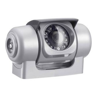
PerfectView CAM50
DE
8
Rückfahrvideokamera
Einbau- und Bedienungsanleitung
EN
23
Rear View Video Camera
Installation and operating manual
FR
37
Caméra vidéo de recul
Notice de montage et d'utilisation
ES
52
Cámara de vídeo de marcha
atrás
Instrucciones de montaje y uso
IT
67
Videocamera per la retromarcia
Istruzioni per I'uso e il montaggio
NL
82
Achteruitrijvideocamera
Montagehandleiding en gebruiks-
aanwijzing
DA
96
Bakvideokamera
Installations- og betjenings-
vejledning
SV
110 Backningsvideokamera
Monterings- och bruksanvisning
NO
123 Ryggevideokamera
Montasje- og bruksanvisning
FI
136 Peruutusvideokamera
Asennus- ja käyttöohje
PL
150 Kamera cofania
Instrukcja montażu i obsługi
RU
165 Видеокамера заднего вида
Инструкция по монтажу и
эксплуатации
CS
180 Couvací kamera
Návod k montáži a obsluze
SK
194 Cúvacia kamera
Návod na montáž a uvedenie do
prevádzky
Advertisement
Table of Contents

Related Manuals for Waeco PerfectView CAM50


Summary of Contents for Waeco PerfectView CAM50
- Page 1 PerfectView CAM50 Rückfahrvideokamera 110 Backningsvideokamera Einbau- und Bedienungsanleitung Monterings- och bruksanvisning Rear View Video Camera 123 Ryggevideokamera Installation and operating manual Montasje- og bruksanvisning Caméra vidéo de recul 136 Peruutusvideokamera Notice de montage et d’utilisation Asennus- ja käyttöohje Cámara de vídeo de marcha 150 Kamera cofania atrás...
- Page 2 PerfectView CAM50...
- Page 3 PerfectView CAM50...
- Page 4 PerfectView CAM50...
- Page 5 PerfectView CAM50 90°...
- Page 6 PerfectView CAM50...
- Page 7 PerfectView CAM50...
-
Page 8: Table Of Contents
PerfectView CAM50 Please read this instruction manual carefully before installation and first use, and store it in a safe place. If you pass on the product to an- other person, hand over this instruction manual along with it. Contents Explanation of symbols ........24 Safety and installation instructions. -
Page 9: Explanation Of Symbols
Explanation of symbols PerfectView CAM50 Explanation of symbols WARNING! Safety instruction: Failure to observe this instruction can cause fatal or serious injury. CAUTION! Safety instruction: Failure to observe this instruction can lead to injury. NOTICE! Failure to observe this instruction can cause material damage and impair the function of the product. - Page 10 Safety and installation instructions PerfectView CAM50 Please observe the following instructions: To prevent short circuits, always disconnect the negative terminal of the vehicle’s electrical system before working on it. If the vehicle has an additional battery, its negative terminal should also be disconnected.
- Page 11 Safety and installation instructions PerfectView CAM50 Observe the following installation instructions: Secure the parts of the camera installed in the vehicle in such a way that they cannot become loose under any circumstances (sudden braking, accidents) and cause injuries to the occupants of the vehicle.
-
Page 12: Scope Of Delivery
Scope of delivery PerfectView CAM50 Do not pull at the cables, as this impairs the sealing and the function of the camera (fig. 6, page 3). The camera is not suitable for submerged operation (fig. 7, page 3). -
Page 13: Technical Description
Technical description PerfectView CAM50 WARNING! Risk of injury! Since rear view systems are designed merely as an additional aid for reversing, it does not relieve you of the duty to take proper care when reversing. Technical description The camera with integrated microphone, which is encased in aluminium housing, transmits image and sound to a monitor via a cable. - Page 14 Notes on the electrical connections PerfectView CAM50 Please observe the following instructions: As far as possible, use original openings or alternative openings for the connecting cable duct, e.g. the paneling edges, ventilation grilles or blank panels. If no openings are available, you must drill holes for the cables.
-
Page 15: Mounting The Camera
Mounting the camera PerfectView CAM50 Mounting the camera Tools required For installation and assembly you will require the following tools: Drill bit set (fig. 1 1, page 2) Drill (fig. 1 2, page 2) Screwdriver (fig. 1 3, page 2) ... - Page 16 Mounting the camera PerfectView CAM50 Observe the following installation instructions: To provide a suitable viewing angle, the camera must be attached at a height of at least 2 m. Ensure that you have a firm place from which to work when mounting the camera.
- Page 17 Mounting the camera PerfectView CAM50 If you want to screw on the camera with self-tapping screws (fig. b, page 5) NOTICE! Risk of damage! The holder may only be attached to steel panels with a minimum thickness of 1.5 mm using self-tapping screws.
- Page 18 Mounting the camera PerfectView CAM50 ➤ Drill a hole of Ø 16 mm near the camera. ➤ Deburr all drill holes that have been made in the sheet metal and apply rust-protection. ➤ Place cable sleeves in all sharp edged ducts.
-
Page 19: Cleaning And Caring For The Camera
Cleaning and caring for the camera PerfectView CAM50 Aligning the camera NOTE If necessary before aligning the camera connect the camera to a monitor and to a power supply (see connecting diagram, fig. i, page 6 ➤ Use the monitor image to align the camera: The monitor image should show the bottom edge of the rear or the bumper of your vehicle (A). -
Page 20: Disposal
Disposal PerfectView CAM50 Disposal ➤ Place the packaging material in the appropriate recycling waste bins wherever possible. If you wish to finally dispose of the product, ask your local recycling centre or specialist dealer for details about how to do this in accordance with the applicable disposal regulations. - Page 21 Technical data PerfectView CAM50 Approval The device has the E11 approval.
- Page 22 Dometic WAECO International GmbH Hollefeldstraße 63 · D-48282 Emsdetten +49 (0) 2572 879-195 · +49 (0) 2572 879-322 Mail: info@dometic-waeco.de · Internet: www.dometic-waeco.de Europe Overseas + Middle East Dometic Austria GmbH Dometic Norway AS Dometic Australia Neudorferstrasse 108...
- Page 23 E C O PerfectView M5L, M7L, M7LX LCD-Monitor 113 LCD-monitor Montage- und Bedienungsanleitung Monterings- och bruksanvisning LCD Monitor 127 LCD-monitor Installation and Operating Manual Monterings- og bruksanvisning Ecran LCD 141 LCD-monitori Instructions de montage Asennus- ja käyttöohje et de service 155 Monitor LCD Pantalla LCD Instrukcja montażu i obsługi...
- Page 24 PerfectView M5L, M7L, M7LX...
- Page 25 PerfectView M5L, M7L, M7LX...
- Page 26 PerfectView M5L, M7L, M7LX E C O E C O...
- Page 27 PerfectView M5L, M7L, M7LX E C O...
- Page 28 PerfectView M5L, M7L, M7LX E C O E C O...
- Page 29 PerfectView M5L, M7L, M7LX C1/C2 MENUE WAECO M5L, M7L C1/C2 MENUE WAECO M7LX...
- Page 30 Explanation of symbols PerfectView M5L, M7L, M7LX Please read this instruction manual carefully before installation and first use, and store it in a safe place. If you pass on the product to another person, hand over this instruction manual along with it. Contents Explanation of symbols .
- Page 31 Safety and installation instructions PerfectView M5L, M7L, M7LX Safety and installation instructions Please observe the prescribed safety instructions and stipulations from the vehicle manufacturer and service workshops. The manufacturer accepts no liability for damage in the following cases: Faulty assembly or connection ...
- Page 32 Safety and installation instructions PerfectView M5L, M7L, M7LX Observe the following installation instructions: CAUTION! Secure the monitor in such a way that it cannot become loose under any cir- cumstances (sudden braking, accidents) and cause injuries to the occu- pants of the vehicle.
- Page 33 Scope of delivery PerfectView M5L, M7L, M7LX NOTICE! Connect it to the correct voltage. Do not use the monitor in areas which – are subjected to direct sunlight, – are subject to strong temperature fluctuations, – have high levels of humidity, –...
- Page 34 Accessories PerfectView M5L, M7L, M7LX Accessories Available as accessory (not included in scope of delivery): Designation Item no. Monitor bracket with support for M5L 9102200049 Monitor bracket with support for M7L 9102200050 Intended use The LCD monitors PerfectView M5L, M7L and M7LX are monitors which are primarily in- tended for use in vehicles.
- Page 35 Technical description PerfectView M5L, M7L, M7LX Control elements The following control elements are located on the monitor: No. in fig. 0, Designation Description page 5 Sensor window for the dimmer function. The brightness of the display is automatically adapted to the ambient light.
- Page 36 Mounting the LCD monitor PerfectView M5L, M7L, M7LX Mounting the LCD monitor Tools required (fig. 1, page 2) For installation and assembly you will require the following tools: Measuring ruler (4) Centre punch (5) Hammer (6) Drill bit set (7) ...
- Page 37 Mounting the LCD monitor PerfectView M5L, M7L, M7LX Choosing the installation location ➤ Place the monitor and the mounting rail on the monitor bracket (fig. a A, page 6). ➤ Place the monitor bracket and the mounting rail onto the support base and secure it using the knurled nuts (fig.
- Page 38 Mounting the LCD monitor PerfectView M5L, M7L, M7LX Connecting the monitor electrically The circuit diagram for the LCD monitor can be found in fig. d, page 7. No. in Designation fig. d, page 7 Monitor 20-pin socket Monitor line 20-pin plug 12–24 V positive cable (red): connected to the positive pole of the ignition (connected positive, terminal 15) or the positive pole of the battery (terminal 30).
- Page 39 Mounting the LCD monitor PerfectView M5L, M7L, M7LX Observe the following instructions when laying the connection cable: Feed the connection cable through existing ducts or other openings where possible, e. g. ventilation grilles. If no suitable ducts or openings are available you will need to drill a hole of ...
- Page 40 Using the LCD monitor PerfectView M5L, M7L, M7LX ➤ If necessary, connect the socket C1 (9) of the connection cable to the plug of the vid- eo source 1 (e. g. camera). ➤ If necessary, connect the socket C2 (10) of the connection cable to the plug of the video source 2 (e.
- Page 41 Using the LCD monitor PerfectView M5L, M7L, M7LX Page 2: – Language: “English” or “German” – Reset (“Default”): Default setting for all parameters – Camera1/Camera2: “Normal” or “Mirrored” – M7LX: Camera3: “Normal” or “Mirrored” – M7LX: Distance: Distance markers (“Setting distance markers (M7LX) (fig. 0, page 5)”...
- Page 42 Cleaning and caring for the LCD monitor PerfectView M5L, M7L, M7LX Using the monitor with two reversing cameras (trailer operation) (fig. c, page 6) You do not need to make any settings to the monitor during operation. The monitor auto- matically detects whether one or two cameras are connected (e.g.
-
Page 43: Technical Data
Disposal PerfectView M5L, M7L, M7LX Disposal ➤ Place the packaging material in the appropriate recycling waste bins wherever possible. If you wish to finally dispose of the product, ask your local recycling centre or specialist dealer for details about how to do this in accordance with the applica- ble disposal regulations. - Page 44 Dometic WAECO International GmbH Hollefeldstraße 63 · D-48282 Emsdetten +49 (0) 2572 879-195 · +49 (0) 2572 879-322 Mail: info@dometic-waeco.de · Internet: www.dometic-waeco.de Europe Overseas + Middle East Dometic Austria GmbH Dometic Norway AS Dometic Australia Neudorferstrasse 108...