Table of Contents
Advertisement
Models:
Pier-38HV
ST-38HV
WARNING: IF THE INFORMATION
IN THESE INSTRUCTIONS IS NOT
FOLLOWED EXACTLY, A FIRE OR
EXPLOSION MAY RESULT CAUS-
ING PROPERTY DAMAGE, PER-
SONAL INJURY, OR DEATH.
Printed in U.S.A. Copyright 2001,
Heat-N-Glo, a division of Hearth Technologies Inc.
20802 Kensington Boulevard, Lakeville, MN 55044
This product is covered by one or more of the following patents: (United States) 4,112,913; 4,408,594; 4,422,426; 4,424,792; 4,520,791; 4,793,322;
4,852,548; 4,875,464; 5,000,162; 5,016,609; 5,076,254 5,191,877; 5,218,953; 5,328,356; 5,429,495; 5,452,708; 5,542,407; 5,613,487; (Australia)
543790; 586383; (Canada) 1,123,296; 1,297,746; 2,195,264; (Mexico) 97-0457; (New Zealand) 200265; or other U.S. and foreign patents pending.
GUIDE
WARNING: IMPROPER INSTALLA-
TION, ADJUSTMENT, ALTERATION,
SERVICE OR MAINTENANCE CAN
CAUSE INJURY OR PROPERTY DAM-
AGE. REFER TO THIS MANUAL. FOR
ASSISTANCE OR ADDITIONAL INFOR-
MATION CONSULT A QUALIFIED IN-
STALLER, SERVICE AGENCY, OR THE
GAS SUPPLIER.
1. This appliance may be installed in an af-
termarket, permanently located, manu-
factured (mobile) home, where not pro-
hibited by local codes.
2. This appliance is only for use with the type
of gas indicated on the rating plate. This
appliance is not convertible for use with
other gases, unless a certified kit is used.
Please contact your Heat-N-Glo dealer for any
questions or concerns. For the number of your
nearest Heat-N-Glo dealer, please call 952-985-6000.
1
Installers Guide
Underwriters
Laboratories Listed
INSTALLERS
Advertisement
Table of Contents

Subscribe to Our Youtube Channel
Related Manuals for Heat-N-Glo Pier-38HV


Summary of Contents for Heat-N-Glo Pier-38HV
- Page 1 Printed in U.S.A. Copyright 2001, Please contact your Heat-N-Glo dealer for any questions or concerns. For the number of your Heat-N-Glo, a division of Hearth Technologies Inc.
-
Page 2: Safety And Warning Information
SAFETY AND WARNING INFORMATION These units MUST use one of the vent systems READ and UNDERSTAND all instructions carefully described in the Installing the Fireplace section of before starting the installation. FAILURE TO the Installers Guide. NO OTHER vent systems or FOLLOW these installation instructions may result components MAY BE USED. -
Page 3: Table Of Contents
Appliance Certification............8 Installation Codes ............... 8 High Altitude Installations ............ 8 Section 2: Getting Started ..........9 Introducing the Heat-N-Glo Gas Fireplaces ....... 9 Pre-installation Preparation ..........9 Section 3: Installing the Fireplace ....... 12 Constructing the Fireplace Chase ........12 Step 1 Locating the Fireplace ........ -
Page 4: Section 1: Approvals And Codes
Approvals and Codes High Altitude Installations Appliance Certification Installers Guide Certification Installation Codes Heat-N-Glo Quality Systems registered by SGS ICS... -
Page 5: Section 2: Getting Started
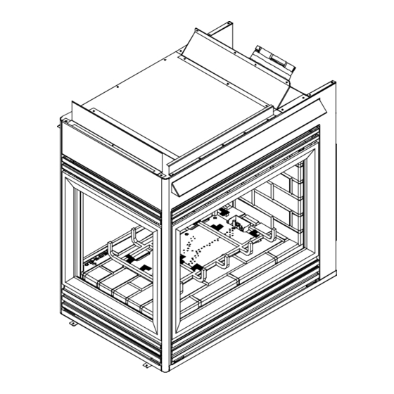
Getting Started Introducing the Heat-N-Glo Gas Fireplaces Warranty Installers Guide Pre-install Preparation Installers Guide... - Page 6 22 11/16 3 1/16 (85mm) (576mm) (79mm) 36 1/16 (915mm) TOP STANDOFFS VENT COLLAR VENT COLLAR GRILL SIDE GLASS DOOR END GLASS DOOR BOTTOM GRILL GAS CONTROLS & LABELS ELECTRICAL GAS LINE ACCESS ACCESS Figure 1. Diagram of the PIER-38HV...
- Page 7 Ø6 5/8 (168mm) 25 7/8 (657mm) 11 5/16 (287mm) ELECTRICAL 38 5/8 ACCESS (981mm) 29 1/8 35 3/16 (739mm) GAS LINE (894mm) ACCESS (52mm) 31 3/16 (792mm) (52MM) 22 11/16 38 1/4 (972mm) 3 3/8 (576mm) (85mm) 3 1/16 (79mm) TOP STANDOFFS VENT COLLAR VENT COLLAR...
-
Page 8: Section 3: Installing The Fireplace
36” Installing the Fireplace PIER-38HV Constructing the Fireplace Chase 36” 36” CAUTION: TREATMENT OF FIRESTOP SPACERS AND ST-38HV CONSTRUCTION OF THE CHASE MAY VARY WITH THE TYPE OF BUILDING. THESE INSTRUCTIONS ARE NOT SUBSTITUTES FOR THE REQUIREMENTS OF LOCAL 36”... -
Page 9: Step 2 Framing The Fireplace
Step 2. Framing the Fireplace CAUTION: MEASURE FIREPLACE DIMENSIONS AND VERIFY FRAMING METHODS AND WALL COVERING DETAILS BEFORE FRAMING. Shows center of 10” x 10” vent framing holes. The center of the hole is 1 inch (25.4mm) above the center of the horizontal vent pipe. 37 1/8 (943mm) 38 3/4... - Page 10 PIER-38HV ST-38HV Vertical Vent Runs Vertical Vent Runs 1” (25mm) 1” (25mm) PIPE CLEARANCE PIPE CLEARANCE 41 1/2” 40 3/8” (1054mm) (1026mm) Horizontal Vent Runs Horizontal Vent Runs FIRESTOP FIRESTOP 3” (75mm) 3” (75mm) PIPE CLEARANCE PIPE CLEARANCE 1 1/2”...
-
Page 11: Step 3 Installing The Vent System
Step 3. Installing the Vent System 6 1/2 6 3/8 A. Vent System Approvals 9 1/4 6 1/2 9 5/8 6 3/8 6 5/8 SL-45D 6 5/8 9 5/8 SL-90D 17-24 6 1/2 11 3/4 5 3/4 6 5/8 SL-17/24D Installers Guide (SL17-24D) SL-12D... - Page 12 STRAIGHT UP VERTICAL BAFFLE KIT (BAF-VERT) Max. Run 24" (610 mm)
- Page 14 VENTING WITH TWO (2) 90° ELBOWS...
- Page 15 H + H 1´ MIN. (305 mm) 2´ MAX. (610 mm) 2´ MAX. (610 mm) 2´ MIN. (610 mm) 2´ MAX. (610 mm) 4´ MAX. (1.22 m) 3´ MIN. (914 mm) 2´ MAX. (610 mm) 6´ MAX. (1.86 m) 4´ MIN. (1.22 m) 2´...
- Page 16 VENTING WITH THREE (3) 90° ELBOWS H + H 1´ MIN. (305 mm) 2´ MAX. (610 mm) 2´ MAX. (610 mm) 2´ MIN. (610 mm) 2´ MAX. (610 mm) 4´ MAX. (1.22 m) 3´ MIN. (914 mm) 2´ MAX. (610 mm) 6´...
-
Page 18: Installing Vent Components
B. Installing Vent Components 1. Attach the First Vent Component to the Starting Collars 2. Continue Adding Vent Components STARTING COLLAR STOVE SEALANT BEAD FIRST VENT COMPONENT 1 INCH (25.4mm) - Page 19 3. Install Support Brackets For Horizontal Runs For Vertical Runs 10" WALL BRACKET (254mm) 1" (25.4 mm) WALL STUD 10" (254mm) VENT PIPE 8 FT. (2.4mm) FLUE OUTLET HEAT SHIELD 1 INCH MIN. TRIM HEAT (25.4mm) SHIELD IF TOO LONG, ADD TO SHIELD IF TOO SHORT EXTERIOR...
- Page 20 For Vertical Runs JOIST CEILING NAILS (4 REQUIRED) CEILING FIRESTOP 10" (254mm) 10" (254mm) CHIMNEY HOLE NAILS (4 REQUIRED) EXISTING CEILING JOISTS FRAMING MEMBERS CEILING RAFTER CEILING CEILING FIRESTOP...
-
Page 21: Vent Termination
C. Vent Termination ROUND CAP TERMINATION For Horizontal Terminations PERFORATION CANNOT BE INSIDE THE WALL 7 1/2" (191mm) MINIMUM TRAPEZOID CAP TERMINATION 7 1/4" (184mm) - Page 22 openable fixed closed J or K 1 2 3 4 1 2 3 4 1 2 3 4 1 2 3 4 CAUTION: IF EXTERIOR WALLS ARE FINISHED WITH VINYL SIDING, IT IS NECESSARY TO INSTALL THE VINYL PROTECTOR KIT TO THE TOP OF THE EXTERIOR FIRESTOP (FOR ALL ROUND TERMINATION CAPS).
- Page 23 For Vertical Terminations HORIZONTAL OVERHANG 2 FT. 2 FT. MIN. VERTICAL MIN. WALL LOWEST DISCHARGE OPENING TERMINATION ROOF PITCH IS X/ 12 H (MIN.) - MINIMUM HEIGHT FROM ROOF TO LOWEST DISCHARGE OPENING NOTE: This also pertains to vertical vent systems in- stalled on the outside of the building.
-
Page 24: Positioning, Leveling, And Securing The Fireplace
Step 4. Positioning, Leveling, and Step 5. The Gas Control Systems Securing the Fireplace Standing Pilot Ignition Direct Spark Ignition (DSI). Standing Pilot Ignition System PIER-38HV ST-38HV Direct Spark Ignition (DSI) System 3/8” (10mm) -
Page 25: Step 6 The Gas Supply Line
Step 7. Gas Pressure Requirements Step 6. The Gas Supply Line Pressure requirements for Heat-N-Glo gas fireplaces are shown in the table below. Pressure Natural Gas Propane Minimum 5.0 inches 11.0 inches Inlet Pressure w.c. w.c. Maximum Inlet 14.0 inches 14.0 inches... -
Page 26: Step 8 Wiring The Fireplace
REMOTE SWITCH 3/16” PIGGYBACK CONNECTOR PIGTAIL BLACK S2 ON/OFF WHITE T2 SWITCH GAS VALUE RED T1 THERMOPILE BLACK S1 THERMOCOUPLE OPTIONAL WALL SWITCH, THERMOSTAT OR REMOTE CAUTION: LABEL ALL WIRES PRIOR TO DISCONNEC- Step 8. Wiring the Fireplace TION WHEN SERVICING CONTROLS. WIRING ERRORS CAN CAUSE IMPROPER AND DANGEROUS OPERA- TION. -
Page 27: Step 9 Finishing
476-500 DSI CONTROL VALVE OPTIONAL REMOTE, WALL SWITCH (NEUTRAL) OR THERMOSTAT (ON CERTIFIED UNITS ONLY) OPTIONAL 100-254A JUNCTION 459-591 (HOT) SWITCHES IGNITOR 120 VAC BLACK WHITE ON/OFF BLUE 501-592 GROUND MODULE WHITE YELLOW GROUND GREEN FIREPLACE CHASSIS BLUE WHITE BLACK FLAME SENSOR/SPARKER ON/OFF SWITCH IGNITION... -
Page 28: Step 10 Installing Trim, Logs, And Ember Material
NEEDED) CAN BE APPLIED AS FACING TO THE FIRE- PLACE SURROUND. SEE THE DIAGRAM BELOW. ST-38HV TOP EDGE SIDE EDGE 0” GAP FIRST GRATE BAR PILOT PIER-38HV ASSEMBLY TOP EDGE SIDE EDGE EMBER 0” GAP MATERIAL DO NOT PLACE EMBER MATERIAL ON FIRST... -
Page 29: Glass Specifications
Step 12. Lighting the Fireplace Step 11. Before Lighting the Fireplace After the Installation Installers Guide... -
Page 30: Section 4: Maintaining And Servicing Your Fireplace
Maintaining and Servicing Your Fireplace Fireplace Maintenance...
Need help?
Do you have a question about the Pier-38HV and is the answer not in the manual?
Questions and answers