
Related Manuals for Amprobe AM-120 TRMS


Summary of Contents for Amprobe AM-120 TRMS
- Page 1 USER'S MANUAL AM-120 TRMS AM-130 TRMS AM-150 TRMS Digital Multimeters Version: 02/2008 / PAEB27309020 BEHA-AMPROBE GmbH In den Engematten 14, 79286 Glottertal Tel.: 07684 8009 - 0, Fax: 07684 8009 410...
- Page 2 This manual is applicable to all meter protection versions or otherwise specified 1) SAFETY Terms in this manual WARNING identifies conditions and actions that could result in serious injury or even death to the user. CAUTION identifies conditions and actions that could cause damage or malfunction in the instrument.
-
Page 3: International Electrical Symbols
WARNING To reduce the risk of fire or electric shock, do not expose this product to rain or moisture. To avoid electrical shock hazard, observe the proper safety precautions when working with voltages above 60 VDC or 30 VAC rms. These voltage levels pose a potential shock hazard to the user. -
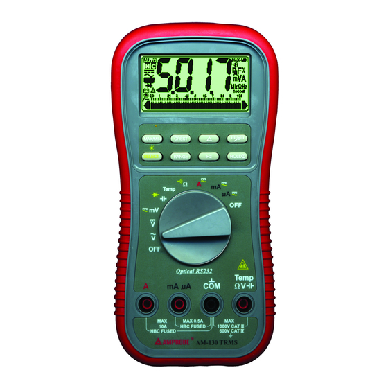
Page 4: Product Description
3) PRODUCT DESCRIPTION Panel Illustration 1) 3-4/5 digits 5000 counts LCD display 2) Push-buttons for special functions & features 3) Selector to turn the Power On or Off and Select a function 4) Input Jack for 10A (20A for 30sec) current function 5) Input Jack for all functions EXCEPT... - Page 5 Analog bar-graph The analog bar graph provides a visual indication of measurement like a traditional analog meter needle. It is excellent in detecting faulty contacts, identifying potentiometer clicks, and indicating signal spikes during adjustments. Average sensing RMS calibrated RMS (Root-Mean-Square) is the term used to describe the effective or equivalent DC value of an AC signal.
-
Page 6: Operation
CMRR (Common Mode Rejection Ratio) Common mode voltage is voltage present on both the COM and VOLTAGE input terminals of a DMM, with respect to ground. CMRR is the DMM's ability to reject common mode voltage effect that can cause digit rattle or offset in voltage measurements. - Page 7 Capacitance, Diode test function Default at . Press SELECT button momentarily to select Diode test function. CAUTION Discharge capacitors before making any measurement. Large value capacitors should be discharged through an appropriate resistance load. Normal forward voltage drop (forward biased) for a good silicon diode is between 0.400V to 0.900V.
- Page 8 Temperature function (AM-130 & AM-150 only) Press SELECT button momentarily to toggle between ° C and ° F readings, and the new setting will be saved automatically in the non-volatile memory as power up default. Note: Be sure to insert the banana plug K-type temperature bead probe with correct polarities.
- Page 9 Resistance, Continuity functions Default at . Press SELECT button momentarily to select Continuity function that is convenient for checking wiring connections and operation of switches. A continuous beep tone indicates a complete wire. CAUTION Using resistance and continuity function in a live circuit will produce false results and may damage the instrument.
- Page 10 Auto leads resistance calibration When entering the 50 range manually by RANGE button for high precision low resistance measurement, this feature will prompt you to short the inputs for calibration. The display shows “Shrt”. Simply short the leads for about 3 seconds until the display shows zero, then the resistance in the leads and in the internal protection circuitry of the meter is compensated automatically.
- Page 11 The instrument equips with an optical isolated interface port at the meter back for data communication. Optional purchase PC interface kit is required to connect the meter to the PC computer (refer to www.amprobe.com). The Data Recording System software equips with a digital meter, an analog meter, a comparator meter, and a Data Graphical...
- Page 12 50ms MAX/MIN at fast 20/s measurement mode (AM-130 only) Press MAX/MIN button momentarily to activate MAX/MIN recording mode. The LCD symbols “MAX MIN” turn on, and the reading update rate will be increased to 20/second. The meter beeps when new maximum or minimum reading is updated. Press the button momentarily to read throughout the Maximum (MAX), Minimum (MIN), and Maximum minus Minimum (MAX-MIN) readings.
- Page 13 Backlighted display Press the SELECT button for 1 second or more to turn on or off the display backlight function. The backlight will also be turned off automatically after 30 seconds to extend battery life. Hold The hold function freezes the display for later view. Press the HOLD button momentarily to activate or to exit the hold function Zoom 5x analog pointer (AM-130 only)
- Page 14 Relative mode (AM-130 only) Relative zero allows the user to offset the meter consecutive measurements with the displaying reading as the reference value. Practically all displaying readings can be set as relative reference value including MAX/MIN feature readings. Press the button momentarily to activate and to exit relative zero mode.
- Page 15 Data Logging mode (AM-150 only) Press the Start button for 1 second or more to start “Strt” or to stop “StoP” the data logging mode. Press the SELECT button momentarily to toggle the LCD display to the measuring data or the logged data item number. Press the Start button momentarily to pause or to continue.
- Page 16 To recall, switch on the meter, then press the start, up, or down arrow button momentarily to “CALL” the logged data. The LCD annunciator “C” will be flashing to indicate on screen logged data review. The logged data can also be downloaded to a PC computer through the meter RS232C capability with the additional RSKIT1 PC interface kit.
- Page 17 4) Press the up (or down) arrow button momentarily while press-and-hold the HOLD button to search throughout the turning points (max, min, max, min, …etc) of the logged data. The LCD annunciator “MAX” or “MIN” will be flashing to indicate a downward or upward turning point.
-
Page 18: Maintenance
Auto Power Off (APO) The Auto Power Off (APO) mode turns the meter off automatically to extend battery life after approximately 17 minutes of no activities. Activities are specified as: 1) Rotary switch or push button operations, and 2) Significant measuring readings of above 10% of range or non-OL readings. - Page 19 Battery and Fuse replacement Battery use: Single 9V battery NEDA1604, JIS006P or IEC6F22; or 9V alkaline battery NEDA1604A, JIS6AM6 or IEC6LF22 AM-120 & AM-130 fuses: Fuse (FS1) for μ AmA current input: 0.63A/500V, IR 200kA, F fuse (FA-6x32/.63); Fuse (FS2) for A current input: 12.5A/500V, IR 20kA, F fuse (FA-12.5A/500V) AM-150 fuses: Fuse (FS1) for μ...
- Page 20 6) Specifications (Applicable to all protection versions or otherwise specified) General Specifications Display: 3-4/5 digits 5000 counts LCD display Update Rate: Digital Data 5 per second nominal; 52 Segments Bar-graph 60 per second nominal AC Sensing: True RMS Operating Temperature: 0°C to 45°C Relative Humidity: Maximum relative humidity 80% for temperature up to 31°C decreasing linearly to 50% relative humidity at 45°C Storage Temperature: -20°C to 60°C, 80% R.H.
- Page 21 Capacitance function is not specified Other function ranges: Total Accuracy = Specified Accuracy + 30 digits. Performance above 3V/m is not specified Power Supply: Single standard 9V battery NEDA1604, JIS006P or IEC6F22 for AM- 120 & AM-130, and single standard 9V alkaline battery NEDA1604A, JIS6AM6 or IEC6LF22 for AM-150 Power Consumption: 2.6 mA typical Low Battery: Below approx.
- Page 22 DC Voltage DC Current RANGE Accuracy RANGE Accuracy Burden Voltage 50.00 mV 0.12% + 2d 500.0μA 0.15mV/μA 500.0 mV 0.06% + 2d 5000μA 0.15mV/μA 0.2%+4d 5.000V, 50.00V, 500.0V, 0.08% + 2d 50.00mA 3.3mV/mA 1000V 500.0mA 3.3mV/mA NMRR:>60dB @ 50/60Hz 5.000A 0.03V/A CMRR:>120dB @ DC, 50/60Hz, Rs=1k 10.00A*...
- Page 23 Ohms Frequency RANGE Accuracy Function Sensitivity Range (Sine RMS) 50.00 0.2% + 6d 300mV 6Hz - 125kHz 500.0 0.1% + 3d 6Hz - 125kHz 5.000k , 50.00k , 500.0k 0.1% + 2d 6Hz - 20kHz 5.000M 0.4% + 3d 500V 6Hz - 1kHz 50.00M 1.5% + 5d...
-
Page 24: Limited Warranty
Please have your dated bill of sale, which must identify the instrument model number and serial number and call the number listed below: BEHA-AMPROBE GmbH In den Engematten 14, 79286 Glottertal Tel.: 07684 8009 - 0, Fax: 07684 8009 410 Please obtain an RMA number before returning product for repair.
Need help?
Do you have a question about the AM-120 TRMS and is the answer not in the manual?
Questions and answers