
Related Manuals for Amprobe AMP-210


Summary of Contents for Amprobe AMP-210
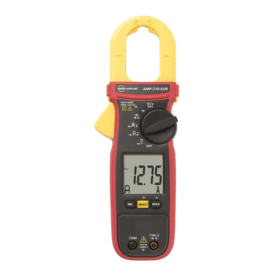
- Page 1 AMP-210 AMP-210-EUR 600A AC TRMS Clamp Multimeter AMP-220 AMP-220-EUR 600A AC / DC TRMS Clamp Multimeter AMP-310 AMP-310-EUR 600A AC TRMS Clamp Multimeter AMP-320 AMP-320-EUR 600A AC / DC TRMS Clamp Multimeter...
- Page 3 AMP-210 / AMP-210-EUR 600A AC TRMS Clamp Multimeter AMP-220 / AMP-220-EUR 600A AC/DC TRMS Clamp Multimeter AMP-310 / AMP-310-EUR 600A AC TRMS Clamp Multimeter AMP-320 / AMP-320-EUR 600A AC/DC TRMS Clamp Multimeter User Manual 7/2014, 6003318 A ©2014 Amprobe Test Tools.
- Page 4 Limited Warranty and Limitation of Liability Your Amprobe product will be free from defects in material and workmanship for one year from the date of purchase unless local laws require otherwise. This warranty does not cover fuses, disposable batteries or damage from accident, neglect, misuse, alteration, contamination, or abnormal conditions of operation or handling.
-
Page 5: Table Of Contents
AMP-210 / AMP-210-EUR Series TRMS Clamp Multimeters CONTENTS SYMBOL ......................3 SAFETY INFORMATION ................. 4 UNPACKING AND INSPECTION ..............5 MEASUREMENTS ................... 6 Measuring AC and DC Voltage ..............7 Voltage detection (NCV) ................8 Measuring AC and DC Current ..............9 Precise Low-Current Measurement ............ - Page 6 AMP-210 / AMP-210-EUR Series TRMS Clamp Multimeters AMP-320 MAX 600A 600V CAT III TRMS PEAK-RMS ZERO SELECT HOLD CAT III 600V Precise Low Current Measuring Location Tactile Barrier Indicator of the Jaw Center Jaw Release for Current Measurement Display Rotary Switch...
-
Page 7: Symbol
24 23 22 Low battery indicator Motor rotation indicator Phase rotation indicator Data hold PEAK-RMS mode Alternative Current (AC) (in-rush current) is active Direct Current (DC) Continuity buzzer is active AC + DC Diode test mode is active Varable Frequency Dive Recording mode is active Negative reading MAX: MAX mode is active... -
Page 8: Safety Information
Direct Current (DC). Battery. Underwriters Laboratories. [Note: Canadian and US.] Complies with European Directives. Conforms to relevant Australian standards. Do not dispose this product as unsorted municipal waste. Contact aqualified recycler. SAFETY INFORMATION The Meter complies with: • UL/IEC/EN 61010-1, CAN/CSA C22.2 No. 61010-1, Pollution Degree 2, Measurement category III 600 V • IEC/EN 61010-2-033 • IEC/EN 61010-2-032... -
Page 9: Unpacking And Inspection
• Do not apply more than the rated voltage, as marked on the Meter, between the terminals or between any terminal and earth ground. • Remove test leads from the Meter before opening the Meter case or battery cover. • Never operate the Meter with the battery cover removed or the case open. -
Page 10: Measurements
AMP-210 AMP-310 AMP-220 AMP-320 MAX 600A MAX 600A 600V CAT III 600V CAT III MAX 600A MAX 600A 600V CAT III 600V CAT III TRMS TRMS TRMS TRMS PEAK-RMS PEAK-RMS ZERO PEAK-RMS ZERO SELECT HOLD SELECT HOLD SELECT HOLD SELECT... -
Page 11: Measuring Ac And Dc Voltage
2. Press SELECT button to choose measurement function: AC V, DC V, DC+AC V, Hz or EF(Non contact voltage detection). The display reflects the chosen function mode. For Model AMP-210 and AMP-220, NCV(EF) function is designed in an independent rotary switch position. See the Non-Contact Voltage Detection chapter for details. -
Page 12: Voltage Detection (Ncv)
Voltage Detection (NCV) Non-Contact Voltage Detection: 1. For AMP-210 and AMP-220 turn the rotary switch to NCV(EF). “EF” is displayed. For AMP-310 and AMP-320, turn the rotary function switch . press SELECT button to toggle to NCV(EF) mode (“EF” is displayed). -
Page 13: Measuring Ac And Dc Current
Measuring AC and DC Current Warning W To avoid electrical shock and injury: • Remove Test Leads before making current measurements. • Do not hold the Meter anywhere beyond the tactile barrier. • Do not use the Meter to measure currents above the maximum rated frequency (400Hz). -
Page 14: Precise Low-Current Measurement
Caution During current measurement keep the jaws away from other current- carrying devices such as transformers, motors or energized wires, as they may negatively influence accuracy of the measurement. Precise Low-Current Measurement W Warning To avoid electrical shock and injury: • Remove Test Leads before making current measurements. -
Page 15: Microamps Μa Measurement
Caution During current measurement keep the jaws away from other current- carrying devices such as transformers, motors or energized wires, as they may negatively influence accuracy of the measurement. Microamps μA Measurement The μA DC ( ) function on the Meter is primarily for HVAC flame sensor testing. -
Page 16: Measuring Resistance, Continuity And Diode
Measuring Resistance, Continuity and Diode W Warning • To avoid false readings that can lead to electrical shock and injury, de- energize the circuit before taking the measurement. • To avoid electrical shock when testing resistance/continuity/diode in a circuit, make sure the power to the circuit is turned off and all capacitors are discharged. -
Page 17: Measuring Capacitance And Temperature
Measuring Capacitance and Temperature Warning W To avoid electrical shock and injury: • When testing capacitor in a circuit, make sure the power to the circuit is turned off and all capacitors are discharged. • When measuring temperature, DO NOT apply the temperature probe to any live conductive parts. -
Page 18: Measuring & 3-Phase Rotation
Measuring & 3-Phase Rotation Measurement is made through the Meter’s terminals L1/L2/L3. Phase Rotation directions are indicated as symbolic (LCD segments) movements on the display. Default mode at . Press SELECT button to toggle between modes. : Hi-sensitivity mode for checking phase rotation of Motors detects relatively low signal outputs generated spinning a motor shaft,. -
Page 19: Auto Power Off
Normal mode for the MAINS circuit: Connect the test lead L1/L2/L3 to the 3-phase mains circuit by using probes and/or alligator clips. If the meter indicates a clockwise movement, the phases connected to L1, L2 and L3 of the meter are L1, L2 and L3 (also known as R, S and T), respectively. -
Page 20: Specifications
SPECIFICATIONS Display 3-5/6 digits 6000 counts Sensing True RMS Polarity Automatic Update rate 5 per second nominal Operating 32 °F to 104 °F (0 °C to 40 °C) temperature Relative Maximum relative humidity 80% for temperature up to humidity 31°C, decreasing linearly to 50% relative humidity at 40 °C Storage -4 °F to 140 °F (-20 °C to 60 °C), <... -
Page 21: Electrical Specifications
AMP-210 and AMP-310 254 g (0.56 lb) for AMP-220 and AMP-320 with batteries installed Weight 208 g (0.46 lb) for AMP-210 and AMP-310 with batteries installed Jaw opening 1.37 in (35 mm) max for AMP-220 and AMP-320 & conductor 1.18 in (30 mm) for AMP-210 and AMP-310... - Page 22 1) Induced error from adjacent current-carrying conductor: < 0.01 A/A 2) Specified with relative zero mode applied to offset the non-zero residual readings, if any. 3) Add 10 LSD to the specified accuracy @ < 4 A 4) AMP-210 and AMP-310, not specified @ < 0.2 A...
- Page 23 2% to specified accuracy for position errors 4) AMP-220 and AMP-320: add 10 LSD to the specified accuracy @ < 9 A 5) AMP-210 and AMP-310: add 10 LSD to specified accuracy @ < 6 A, and not specified @ < 0.2 A...
- Page 24 DC+AC Current (AMP-220 and AMP-320 only) 1) 2) Range Accuracy 60.00 A , 600.0 A ± (2.2 % + 7 LSD) @ DC, 50 Hz to 100 Hz 60.00 A , 600.0 A ± (2.7 % + 7 LSD) @ 100 Hz to 400 Hz 1) Induced error from adjacent current-carrying conductor: <...
-
Page 25: Maintenance And Repair
MAINTENANCE AND REPAIR If the Meter fails to operate, check battery, test leads, etc., and replace as necessary. Double check the following: 1. Replace the fuse or battery if the meter does not work. 2. Review the operating instructions for possible mistakes in operating procedure. - Page 26 Visit www.Amprobe.com for • Catalog • Application notes • Product specifications • User manuals Amprobe ® www.Amprobe.com info@amprobe.com Everett, WA 98203 Tel: 877-AMPROBE (267-7623) Amprobe Europe ® Beha-Amprobe In den Engematten 14 79286 Glottertal, Germany Please Tel.: +49 (0) 7684 8009 - 0...
Need help?
Do you have a question about the AMP-210 and is the answer not in the manual?
Questions and answers
How do I get the beeper to beep when checking continuity?
To enable the beeper on the Amprobe AMP-210 when checking continuity:
1. Connect the black test lead to the COM terminal and the red test lead to the Ω terminal.
2. Turn the rotary switch to the continuity/diode/resistance position.
3. Press the SELECT button to choose the continuity function.
4. Connect the probes across the circuit or component.
The beeper will automatically sound if the circuit resistance is ≤ 10 Ω.
This answer is automatically generated