Table of Contents
Advertisement
Quick Links
Advertisement
Table of Contents

Subscribe to Our Youtube Channel
Related Manuals for Amprobe AM-100


Summary of Contents for Amprobe AM-100
- Page 1 USER'S MANUAL AM-100 AM-105 TRMS AM-110 TRMS Digital Multimeters...
- Page 2 1) SAFETY This manual contains information and warnings that must be followed for operating the instrument safely and maintaining the instrument in a safe operating condition. If the instrument is used in a manner not specified by the manufacturer, the protection provided by the instrument may be impaired.
-
Page 3: International Electrical Symbols
WARNING To reduce the risk of fire or electric shock, do not expose this product to rain or moisture. To avoid electrical shock hazard, observe the proper safety precautions when working with voltages above 60 VDC or 30 VAC rms. These voltage levels pose a potential shock hazard to the user. -
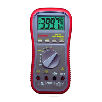
Page 4: Product Description
3) PRODUCT DESCRIPTION This user's manual uses only representative model for illustrations. Please refer specification details for function availability to each model. 1) 3-3/4 digits 4000 counts LCD display 2) Push-buttons for special functions & features 3) Selector to turn the Power On or Off and select a function 4) Input Jack (+) for 10A... -
Page 5: Operation
4) OPERATION DC Voltage, AC Voltage, & Hz Frequency functions Note: 1) AC 400.0mV range selection is by RANGE button manually, and is specified from AC 10mV (AC 40mV for True RMS models AM-105 & AM-110) and up. 2) DC 400.0mV range is designed with 1000MΩ high input impedance for least current drain in measuring small signals, and can cope better with most commercially available voltage output transducers and adapters. - Page 6 Ω Resistance, and Continuity functions Defaults at Ω. Press SELECT button momentarily to select Continuity function which is convenient for checking wiring connections and operation of switches. A continuous beep tone indicates a complete wire. CAUTION Using Resistance, Continuity, Diode or Capacitance function in a live circuit will produce false results and may damage the instrument.
- Page 7 Diode test, Capacitance functions Defaults at Ω. Press SELECT button momentarily 2 times to select Diode test function. Normal forward voltage drop (forward biased) for a good silicon diode is between 0.400V to 0.900V. A reading higher than that indicates a leaky diode (defective).
- Page 8 Defaults at degree C (Celsius). Press SELECT button momentarily to select degree F (Fahrenheit). You can also use a plug adapter (Optional purchase) with banana pins to type-K socket to adapt other type-K standard mini plug temperature probes (refer to www.amprobe.com).
- Page 9 Relative zero mode Relative zero mode allows the user to offset the meter consecutive measurements with the displaying reading as the reference value. The display will now show readings relative to the stored reference value. That is, display = reading - stored value. Press button momentarily to activate or to exit relative zero mode.
-
Page 10: Maintenance
HOLD The hold feature freezes the display for later view. Press the HOLD button momentarily to activate or to exit the hold feature. The max feature compares and displays the measured maximum value as fast as 25ms in a single range, and with automatic up range capability. Press the MAX button for 1 second or more to activate or to exit the max feature in the voltage or current functions. - Page 11 Battery and Fuse replacement Battery use: Standard 1.5V AAA Size (NEDA 24A or IEC LR03) battery X 2 Protection-reinforced CE Version fuses: Fuse (FS1) for µAmA current input: 0.63A/500V, IR 200kA, F fuse (FA-6x32/.63); Fuse (FS2) for A current input: 12.5A/500V, IR 20kA, F fuse (FA-12.5A/500V); Battery replacement: Loosen the 2 screws from the battery access door of the case bottom.
- Page 12 C -40 C), or otherwise specified Sensing: Average sensing for AM-100. True RMS for AM-105 TRMS & AM-110 TRMS Safety: The meter (all versions) is protected, against the users, by double insulation per CSA C22.2 No. 1010-1-92, EN61010-1(1995) and IEC61010-1(1995) to CAT II 1000V &...
- Page 13 Sleep Mode Timing: Idle for 30 minutes Sleep Mode Consumption: 300µA typical for AM100; 360µA typical for AM-105 TRMS & AM-110 TRMS Dimension: L193mm X W97mm X H46 Weight: 370 gm Special Features: 25ms Max Hold; Data Hold; Relative zero mode; Beep-jack™ input warning;...
- Page 14 DC Current Capacitance RANGE Accuracy Burden RANGE* Accuracy** Voltage 500.0nF, 5.000µF, 2.0% + 5d 3.5%*** + 6d 400.0µA 0.15mV/µA 50.00µF, 500.0µF, 1.2% + 3d 4000µA 0.15mV/µA 3000µF 40.00mA 2.0% + 5d 3.3mV/mA *Additional 50.00nF range accuracy is not 400.0mA 1.2% + 3d 3.3mV/mA specified 4.000A...
-
Page 15: Limited Warranty
Please have your dated bill of sale, which must identify the instrument model number and serial number and call the number listed below: Repair Department ATP – Amprobe, TIF, Promax Miramar, FL Phone: 954-499-5400 800-327-5060 Fax: 954-499-5454 Website: www.amprobe.com...
Need help?
Do you have a question about the AM-100 and is the answer not in the manual?
Questions and answers