
Related Manuals for Amprobe AM-140-A


Summary of Contents for Amprobe AM-140-A
- Page 1 AM-140-A AM-160-A Precision DMM with TRMS & PC Connection Users Manual • Mode d’emploi • Bedienungshandbuch • Manual d’Uso • Manual de uso 1.800.561.8187 information@itm.com www. .com...
- Page 2 AM-140-A AM-160-A Precision DMM with TRMS & PC Connection Users Manual May 2010, Rev.1 ©2010 Amprobe Test Tools. All rights reserved. Printed in Taiwan 1.800.561.8187 information@itm.com www. .com...
- Page 3 Test Tools distributor for an exchange for the same or like product. Please check the Additionally, in the United States and Canada In-Warranty repair and replacement units can also be sent to a Amprobe® Test Tools Service Center (see next page for address). Non-Warranty Repairs and Replacement – US and Canada Non-warranty repairs in the United States and Canada should be sent to a Amprobe®...
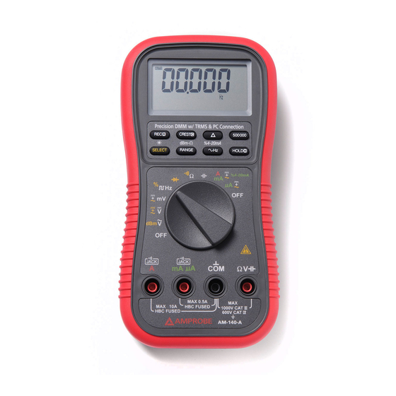
- Page 4 AM-140-A / AM-160-A Precision DMM with TRMS & PC Connection 5-4/5 digits 500000 counts LCD display Push-buttons for special functions & features Selector to turn the Power On or Off and select a function Input Jack for 10A (+) (20A for 30sec) current, and for T2 (-) function Input Jack (+) for all functions EXCEPT current (µA, mA, A) and...
-
Page 5: Table Of Contents
CONTENTS SYMBOLS .......................1 UNPACKING AND INSPECTION ................3 FEATURES .......................3 OPERATION ......................5 AC Voltage, DC Voltage, DC+AC Voltage, & Hz Line Level Frequency ..5 Hz Logic Level Frequency and % Duty Cycle functions ......7 T1-T2 Dual Channels Temperature function (AM-160-A only) ......8 ... -
Page 6: Symbols
No. 61010.1-0.92 to Category III 1000 Volts AC & DC and Category IV 600 Volts AC & DC. AM-140-A Terminals (to COM) measurement category: V : Category III 1000 Volts AC & DC, and Category IV 600 Volts AC & DC. - Page 7 Per IEC61010-1 2nd Ed. (2001) Measurement Category Measurement Category IV (CAT IV) is for measurements performed at the source of the low-voltage installation. Examples are electricity meters and measurements on primary overcurrent protection devices and ripple control units. Measurement Category III (CAT III) is for measurements performed in the building installation.
-
Page 8: Unpacking And Inspection
Electromagnetic compatibility directive 2004/108/EC UNPACKING AND INSPECTION Your shipping carton should include: 1 AM-140-A or AM-160-A Meter 1 Test Leads (Black x 1; Red x 1) 1 K Type thermal couple with banana plug (For AM-160-A only) 1 Users Manual 1 Single Alkaline 9V battery;... - Page 9 AC True RMS AC True RMS, normally refers as True RMS, identifies a DMM function that is AC coupled, and responds accurately only to the effective RMS AC component value regardless of the waveforms. However, DC component plays an important role in the distorted non-symmetrical waveforms, and will also be of interest sometimes.
-
Page 10: Operation
measurements. This series has a CMRR specifications of > 80dB at DC to 60Hz in ACV function; and > 120dB at DC, 50 and 60Hz in DCV function. If neither NMRR nor CMRR specification is specified, a DMM’s performance will be uncertain. Analog bar-graph The analog bar graph provides a visual indication of measurement like a traditional analog meter needle. - Page 11 1.800.561.8187 information@itm.com www. .com...
-
Page 12: Hz Logic Level Frequency And % Duty Cycle Functions
Note: Line Level Frequency measuring function input sensitivity varies automatically with voltage (or current) function range selected. The lower the measuring range the higher the sensitivity. That is, mV function has the highest and the 1000V range has the lowest as in voltage function ranges. It is recommended to first measure the signal voltage (or current) level then activate the Hz function in that voltage (or current) range to automatically get the most appropriate trigger level. -
Page 13: T1-T2 Dual Channels Temperature Function (Am-160-A Only)
Note: Unlike the Line Level Frequency measuring function as previously stated, this Logic Level Frequency function is set only at the highest input sensitivity for measuring digital type electronic signals. T1-T2 Dual Channels Temperature function (AM-160-A only) Press SELECT button momentarily to toggle between °C and °F readings, and the new setting will be saved automatically in the non-volatile memory as power up default. -
Page 14: Resistance, Continuity Functions
Resistance, Continuity functions Press SELECT button momentarily to toggle between and Continuity functions. The new setting will be saved automatically to the non-volatile memory as power up default. Continuity function is convenient for checking wiring connections and operation of switches. A continuous beep tone indicates a complete wire. -
Page 15: Μa, Ma, A, And %4-20Ma Current Functions
Note: Normal forward voltage drop (forward biased) for a good silicon diode is between 0.400V to 0.900V. A reading higher than that indicates a leaky diode (defective). A zero reading indicates a shorted diode (defective). An OL indicates an open diode (defective). Reverse the test leads connections (reverse biased) across the diode. -
Page 16: Pc-Comm Computer Interface Capabilities
�Warning When measuring a 3-phase system, special attention should be taken to the phase-to-phase voltage that is significantly higher than the phase- to-earth voltage. To avoid exceeding the voltage rating of the protection fuse(s) accidentally, always consider the phase-to-phase voltage as the working voltage for the protection fuse(s). -
Page 17: Max/Min Recording Mode
MAX/MIN RECORDING mode Press REC button momentarily to activate MAX/MIN recording mode. The LCD annunciators “R” and “MAX MIN” turn on. The meter beeps when new maximum or minimum reading is updated. Press the button momentarily to read throughout the Maximum (MAX), Minimum (MIN), and Maximum minus Minimum (MAX-MIN) readings. -
Page 18: Manual Or Auto-Ranging
Manual or Auto-ranging Press the RANGE button momentarily to select manual-ranging mode, and the meter will remain in the range it was in, the LCD annunciator turns off. Press the button momentarily again to step through the ranges. Press and hold the button for 1 second or more to resume auto-ranging mode. -
Page 19: Specification
En61010-1 2nd ed., Ul61010-1 2nd ed. & Can/csa c22.2 No. 61010.1-0.92 To category III 1000v AC & DC and category IV 600V AC & DC Am-140-a terminals (to COM) measurement category: V : Category III 1000 VAC & VDC and category iv 600 VAC & VDC. - Page 20 Low battery: Below approx. 7V Apo timing: Idle for 17 minutes Apo consumption: 55µA typical for am-140-a; 30µA typical for am- 160-a Dimension: L186mm x W87mm x H35.5mm (7.3in x 3.4in x 1.4in); L198mm x W97mm x H55mm (7.8in x 3.8in x 2.2in) with holster...
- Page 21 < 5:1 at full scale & < 10:1 at half scale, and with frequency components within the specified frequency bandwidth for non-sinusoidal waveforms. DC Voltage Range AM-160-A AM-140-A Accuracy 500.00 MV, 5.0000V, 0.02% + 2D 0.03% + 2D 50.000V 500.00V...
- Page 22 PAC & AC+DC Voltage Range AM-160-A AM-140-A Accuracy* 20HZ -- 45HZ 500.00MV, 5.0000V, 1.5% + 60D 50.000V UNSPEC’D 500.00V, 1000.0V UNSPEC’D 45HZ -- 300HZ 500.00MV 0.3% + 20D 5.0000V, 50.000V 0.8% + 20D 0.8%+60D 500.00V,1000.0V 0.4% + 40D 300HZ -- 5KHZ 300HZ -- 1KHZ 500.00MV...
- Page 23 cmrr: >80db @ dc to 60hz, rs=1k input impedance: 10m 30pf nominal (80pf nominal for 500mv range) residual reading less than 50 digits with test leads shorted. DBM: at 600, -11.76dbm to 54.25dbm accuracy: 0.25db + 2d (@40hz -- 20khz) input impedance: 10m, 30pf nominal selectable reference impedance of 4, 8, 16, 32, 50, 75, 93, 110, 125, 135, 150, 200, 250, 300, 500, 600,800, 900, 1000, 1200...
- Page 24 45mV/A 10.000A* 0.5%+20D 45mV/A *10A continuous, >10A to 15A (TO 20A for AM-160-A) for 30 second max with 5 minutes cool down interval AC & AC+DC Current AM-160-A AM-140-A Range Burden Voltage Accuracy 50HZ -- 60HZ 500.00µA 0.15mV/µA 5000.0µA 0.15mV/µA 50.000mA...
- Page 25 1KHZ – 10KHZ 500.00µA 0.15mV/µA 5000.0µA 0.15mV/µA 2.0%+50D UNSPEC’D 50.000mA 3.3mV/mA 500.00mA 3.3mV/mA 5.0000A UNSPEC'D UNSPEC'D 45mV/A 10.000A* *10A continuous, >10A to 15A (to 20A FOR AM-160-A) for 30 second max with 5 minutes cool down interval DC LOOP CURRENT %4--20MA 4mA = 0% (zero) 20mA = 100% (span) Resolution: 0.01%...
-
Page 26: Maintenance And Repair
1000V 900V 10HZ ~ 10KHZ Accuracy: 0.02%+4d Hz Logic Level Frequency Range Accuracy 5.0000HZ--2.00000MHZ 0.002%+4D Sensitivity: 2.5VP square wave %DUTY CYCLE Range Accuracy 0.1% -- 99.99% 3D/KHZ+2D Input frequency: 5HZ -- 500 KHZ, 5V logic family MAINTENANCE AND REPAIR WARNING To avoid electrical shock, disconnect the meter from any circuit, remove the test leads from the input jacks and turn OFF the meter before opening the case. -
Page 27: Trouble Shooting
Battery and Fuse Replacement Battery use: 9V alkaline battery NEDA1604A, JIS6AM6 or IEC6LF22 AM-140-A Fuse (FS1) for µAmA current input: 1A/600V, IR 10kA or better, F fuse; Fuse (FS2) for A current input: 10A/600V, IR 100kA or better, F fuse AM-160-A Fuse (FS1) for µAmA current input: 0.44A/1000V, IR 10kA or better, F fuse... - Page 28 Fuse replacement: Loosen the 4 screws from the case bottom. Lift the end of the case bottom nearest the input jacks until it unsnaps from the case top. Replace the blown fuse(s) and/or the battery. Replace the case bottom, and ensure that all the gaskets are properly seated and the two snaps on the case top (near the LCD side) are engaged.
- Page 29 1.800.561.8187 information@itm.com www. .com...
Need help?
Do you have a question about the AM-140-A and is the answer not in the manual?
Questions and answers