
Related Manuals for Liebert MATRIX S 004-016


Summary of Contents for Liebert MATRIX S 004-016
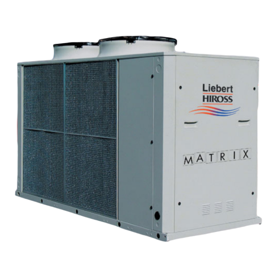
- Page 1 [004-016] HIGH PERFORMANCE AIR COOLED CHILLER SERVICE MANUAL English Cod. 272491 Rev. 25.05.2005 Issued by T.D.Service...
-
Page 3: Table Of Contents
Caution It is recommended that: the manual is retained for the entire service life of the machine; the user reads the manual carefully before carrying out any operations on the machine; the machine is used exclusively for the purpose for which it is intended; incorrect use of the machine shall release the manufacturer from any liability. -
Page 4: Introduction
Tab. 5. In any case outdoor temperatures aver 45ûC are not admitted; such limits are determined by Liebert Hiross accepts no present or future responsibility for electrical and electronic components fitted on units; damage to persons, things or to the machine itself due to opera- Maximum water flow allowed: depending on the pressure tors’... -
Page 5: Transport
Note: 8) Install, at the highest points in the circuit, apparatus which Avoid positioning in areas with possible reverberation of the allows the bleeding of air and possibly the filling of glycol; sound waves, which can adversely effect the noise levels. 9) Place a drain valve at the lowest point in the circuit and im- mediately at the outlet of the water chiller;... -
Page 6: Connection Of The Safety Valve Discharge
Tab. a -- Ethylene glycol to be added to water (% in ALWAYS CHARGE THE HYDRAULIC CIRCUIT WITH THE RE- weight of total mixture) QUIRED GLYCOL % NECESSARY FOR THE MINIMUM AMBI- ENT TEMPERATURE AT THE INSTALLATION SITE. FAILING Ethylene glycol TO COMPLY WITH THIS INSTRUCTION SHALL INVALIDATE (% in weight) THE UNIT WARRANTY. -
Page 7: Electrical Connections
Fig. c -- Sizing of the expansion vessel The total volume of the expansion vessel is calculated with the following formula: C x e 1 - - where: C=quantity of water inside the system expressed in litres e=water expansion coefficient, with water at 10ûC as a reference Pi=absolute pressure of initial charging, equivalent to the vessel pre ---charge pressure (typical value 2.5 bara) Pf=absolute final tolerated pressure, lower than the operating pressure of the safety valve calibration... -
Page 8: First Start
4.2 --- First start ---up 4.6 --- Microprocessor control (or after a long stop) Consult the ”Microface and Hiromatic” Service Manual. Operate as follows: 5 --- Refrigerant and Oil Charge 1) At least 8 hours before the start ---up, power the crank- case heaters (if any, see point 4) by setting the main iso- lator switch ON. -
Page 9: Oil Charge
5.2 --- Oil charge 1) Take a clean, dry, transparent container (with volume cal- ibrations) and fill it with at least twice the amount of oil re- Contact the Technical Support Department for the specifications quired. of the oil to be used for topping up; the oil changes according to 2) Isolate the compressor by closing the cock on the liquid line. -
Page 10: Maintenance
7 --- Maintenance 7.1 --- Spare parts The Maintenance Programme below must be carried out by a qualified technician, preferably working under a maintenance The use of original spare parts is recommended. contract. When placing an order refer to the ”Component List” enclosed Before any intervention on the unit or accessing the inner com- with the machine and quote the unit model no. -
Page 11: Water Chiller With Total Heat Recovery (100%)
8.5 --- Water chiller with inertia tank The water temperature at the recuperator inlet (in stable operat- ing conditions) must be in the range of 25ûC --- 45ûC, with an out- The machine can be supplied complete with a buffer tank; it per- let differential of between 3.5ûC --- 8ûC. -
Page 12: Tables
Tab. 1 --- Internal hydraulic volume Model Unit volume Model Unit volume (*) Add the tank’s volume for the units with optional buffer tank Tab. 2 --- Partial heat recovery (20%) Model Heating capacity 10,8 14,8 18,2 21,6 29,6 36,4 44,3 Water flow 0,516... - Page 13 Tab. 4 --- Electrical characteristics CBH -- R 407C Size Power supply 400 V / 3 Ph / 50 Hz Compressors power input 13.8 18.6 23.5 13.8 18.3 23.8 27.3 36.7 46.5 56.8 Compressors nominal current Compressor max. current Fan power input 1.80 Fan nominal current Fan max.
- Page 14 SBH -- R 407C Size Power supply 400 V / 3 Ph / 50 Hz Compressors power input 14.5 19.7 24.4 14.5 19.4 24.8 28.9 39.2 48.6 59.0 Compressors nominal current Compressor max. current Fan power input 1.90 Fan nominal current Fan max.
- Page 15 Tab. 5 --- Operating limits CBH -- R 407C Size Working Range Max. outdoor air temperature ûC 43.5 44.0 42.5 43.5 44.0 42.5 44.0 44.5 43.0 44.0 Safety Device Settings High pressure switch Barg 26.0 High pressure safety valve Barg 28.0 / 29.0 Low pressure switch Barg...
- Page 16 Tab. 6 --- Noise levels The following table indicates the overall sound pressure level at full load conditions, measured 1m from the unit, according to ISO 3774, with an outdoor temperature of 35 ûC and referred to free field conditions. Total Total Total...
- Page 17 Tab. 8 --- Pump set characteristics (opt.) 2 pole pump set, standard head pressure (data refers to each pump) Models Water flow 6.83 9.42 11.36 6.83 9.27 11.53 13.35 18.39 22.20 28.36 Available head pressure Water flow 6.66 9.32 11.67 6.66 9.16 11.85...
-
Page 18: Drawings
Fig. 1 --- Service areas (top view) 1000 1000 (*) Ordinary maintenance area Extraordinary maintenance area Notes: Minimum distance between 2 units from condensing coil side = 2m Do not obstruct the air exiting the fans for a minimum distance of 2.5m (*) 1500 mm (with 160 --- 200 Lt Tank);... - Page 19 Fig. 2 --- Lifting instructions with tubes ”A” ”C” PROTECTION PLANK ”B” RIGID STRUTS (POSSIBILY STEEL) PART. “A” LIFTING SYSTEM WITH TUBES BELT OR CHORD BLOCKING PEG (NOT SUPPLIED) LIFTING TUBE PART. “A” (NOT SUPPLIED) (BASE HOLES Ø45) PART. “A” SPLIT PIN (NOT SUPPLIED) N.B:...
- Page 20 Fig. 3 --- Lifting instructions with straight shackle N.B.: LIFT IN THE BARICENTRE LINE “G” OF THE UNIT ”A1” ”A2” ”G” LIFTING SYSTEM WITH ”Xg” STRAIGHT SHACKLE PART. “A” ”G” STRAIGHT SHACKLE Ø 14 (UNI 1947) “A” TYPE PART. “A” (OPTIONAL) N.B: The capacity of the lifting gear must be adequate to lift the load in question.
- Page 21 Baricentre “G” --- CBH --- CLH --- CQH Unit baricentre position “G” --- (without water) Without tank With tank Models Models “Xg” “Yg” “Xg” “Yg” CBH 004 0.80 0.55 0.88 0.55 CBH 006 0.77 0.52 0.85 0.54 CBH 007 0.78 0.53 0.86 0.54...
- Page 22 Baricentre “G” --- SBH --- SLH --- SQH Unit baricentre position “G” --- (without water) Without tank With tank Models Models “Xg” “Yg” “Xg” “Yg” SBH 004 0.84 0.55 0.91 0.56 SBH 006 0.81 0.53 0.88 0.54 SBH 007 0.83 0.53 0.89 0.54...
- Page 23 Fig. 4 --- Support positions and loads (Note: weights refer to standard units) CBH - CLH - CQH ”A” FOOT PRINT d=14 ”B” ”C” ”C” ”D” ”E” ”D” Dimensions --- CBH --- CLH --- CQH Dimensions (mm) Model Size 004---006---007---204---206---207 004---006---204---206 2000 1760...
- Page 24 Weight distribution with tank --- CBH --- CLH --- CQH Weight distribution (kg) W 10 Model Size Not available Not available Not available Not available Not available Not available Not available Not available Not available...
- Page 25 Fig. 5 --- Support positions and loads (Note: weights refer to standard units) SBH - SLH - SQH ”A” FOOT PRINT d=14 ”B” ”C” ”C” ”D” ”E” ”D” Dimensions --- SBH --- SLH --- SQH Dimensions (mm) Model Size 004---006---007---204---206---207 004---006---204---206 2000 1760...
- Page 26 Weight distribution with tank --- SBH --- SLH --- SQH Weight distribution (kg) W 10 Model Size Not available Not available Not available Not available Not available Not available Not available Not available Not available...
- Page 27 Fig. 6 --- Rubber anti---vibration support Rubber support dimensions Rubber support installation Unit base Fixing screw Screw anchor (not supplied) Cement base Access hole for support fixing Single support code Code (mm) (mm) (mm) (mm) (mm) (mm) (mm) (mm) 270327 11.0 Rubber supports Support...
-
Page 29: Circuits
Fig. 8 --- Refrigerant circuit (std.) with partial recovery (opt.) CBH/CLH/CQH / SBH/SLH/SQH 004---006---007 HEAT RECOVERY WATER OUTLET 1” GAS MALE (OPT.) HEAT RECOVERY WATER INLET 1” GAS MALE (OPT.) CHILLED WATER INLET 2” GAS MALE CHILLED WATER OUTLET 2” GAS MALE Refrigerant components Item Description... - Page 30 Fig. 9 --- Refrigerant circuit (std.) with partial recovery (opt.) CBH/CLH/CQH / SBH/SLH/SQH 204---206---207---008---011---014---016 HEAT RECOVERY WATER OUTLET ØG --- GAS MALE (OPT.) HEAT RECOVERY WATER INLET ØG --- GAS MALE (OPT.) CHILLED WATER INLET ØH --- GAS MALE CHILLED WATER OUTLET ØH --- GAS MALE CBH / CLH / CQH / SBH / SLH / SQH Ø...
- Page 31 Fig. 10 --- Refrigerant circuit with total recovery (opt.) CBH/CLH/CQH 004---006---007 ONLY FOR: CBH 007 CLH/CQH 006--- 007 HEAT RECOVERY WATER OUTLET 2” GAS MALE HEAT RECOVERY WATER INLET 2” GAS MALE CHILLED WATER INLET 2” GAS MALE CHILLED WATER OUTLET 2”...
- Page 32 Fig. 11 --- Refrigerant circuit with total recovery (opt.) CBH/CLH/CQH 204---206---207---008---011---014---016 ONLY FOR: ONLY FOR: CBH 014--- 016 CBH 014--- 016 CLH/CQH 011--- 014--- 016 CLH/CQH 011--- 014--- 016 HEAT RECOVERY WATER OUTLET ØG --- GAS MALE HEAT RECOVERY CHILLED WATER WATER INLET INLET ØG --- GAS MALE...
- Page 33 Fig. 12 --- Hydraulic circuit --- CBH/CLH/CQH 004---006---007---204---206---207 LIEBERT--- HIROSS UNIT ONLY WITH TANK VERSION NOT AVAILABLE IN 204--- 206--- 207 MODELS ONLY WITH PUMP VERSION CHILLED WATER INLET 2” GAS MALE ONLY FOR 004--- 006--- 007 MODELS CHILLED WATER OUTLET 2”...
- Page 34 Fig. 13 --- Hydraulic circuit --- CBH/CLH/CQH 008---011---014---016 LIEBERT--- HIROSS UNIT ONLY WITH TANK VERSION ONLY WITH PUMP VERSION CHILLED WATER INLET ” GAS MALE CHILLED WATER OUTLET ” GAS MALE Hydraulic components Item Description Item Description Evaporator Control temperature sensor Evaporator antifreeze heater (Opt.)
- Page 35 Fig. 14 --- Hydraulic circuit --- SBH/SLH/SQH 004---006---007---204---206---207 LIEBERT--- HIROSS UNIT ONLY WITH TANK VERSION NOT AVAILABLE IN 204--- 206--- 207 MODELS ONLY WITH PUMP VERSION CHILLED WATER INLET 2” GAS MALE ONLY FOR 004--- 006--- 007 MODELS CHILLED WATER OUTLET 2”...
- Page 36 Fig. 15 --- Hydraulic circuit --- SBH/SLH/SQH 008---011---014---016 LIEBERT--- HIROSS UNIT ONLY WITH TANK VERSION ONLY WITH PUMP VERSION CHILLED WATER INLET ” GAS MALE CHILLED WATER OUTLET ” GAS MALE Hydraulic components Item Description Item Description Flow switch (unit without tank, Opt. without pumps) Evaporator Evaporator antifreeze heater (Opt.)
- Page 37 Produsent erklærer herved at dette produktet er i samsvar med EU-direktiver: Fabrikant erklærer herved, at dette produkt opfylder kravene i EU direktiverne: Since the Liebert HIROSS Company has a policy of continuous Ο ΚατασÀευαστÞj δηλþνει üτι το παÃüν πÃοΪüν εßναι ÀατασÀευασmÝνο αýmφωνα mε τιj οδηγßεj τηj Ε.Ε.: product improvement, it reserves the right to change design and specifications without previous notice.
- Page 38 Tel. +39 049 9719111 Telefax +39 049 5841257 Internet : www.liebert-hiross.com Liebert HIROSS Since the Liebert HIROSS Company has a policy of continuous is a division of product improvement, it reserves the right to change design and EMERSON specifications without previous notice.
Need help?
Do you have a question about the MATRIX S 004-016 and is the answer not in the manual?
Questions and answers