Table of Contents
Advertisement
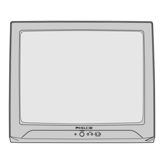
POWER
- VOL +
CH
MENU
In the interests of user-safety (Required by safety regulations in some countries) the set should be restored to its
original condition and only parts identical to those specified should be used.
ELECTRICAL SPECIFICATIONS .......................................................................................................... 1
IMPORTANT SERVICE SAFETY PRECAUTION ................................................................................. 2
LOCATION OF USER'S CONTROL ...................................................................................................... 4
INSTALLATION AND SERVICE INSTRUCTIONS ................................................................................ 5
CHASSIS LAYOUT ............................................................................................................................... 11
BLOCK DIAGRAM ............................................................................................................................... 12
SCHEMATIC DIAGRAMS .................................................................................................................... 14
PRINTED WIRING BOARD ASSEMBLIES ......................................................................................... 17
REPLACEMENT PARTS LIST .............................................................................................................20
PACKING OF THE SET .......................................................................................................................23
POWER INPUT .................................................... AC 120 V, 60 Hz
POWER RATING ................................................................... 69 W
PICTURE SIZE ................................ 1,194cm2 (185.1Square inch)
CONVERGENCE ............................................................. Magnetic
SWEEP DEFLECTION .................................................... Magnetic
FOCUS ............................................... Hi-Bi-Potential Electrostatic
INTERMEDIATE FREQUENCIES
Picture IF Carrier Frequency ..................................... 45.75 MHz
Sound IF Carrier Frequency ...................................... 41.25 MHz
Color Sub-Carrier Frequency .................................... 42.17 MHz
AUDIO POWER
OUTPUT RATING ..................................................... 1 W (RMS)
SERVICE MANUAL
MODEL
CONTENTS
ELECTRICAL SPECIFICATIONS
SPEAKER
SIZE ...................................................................... 8 cm (Round)
VOICE COIL IMPEDANCE ............................ 32 ohm at 400 Hz
ANTENNA INPUT IMPEDANCE
VHF/UHF ..................................................... 75 ohm Unbalanced
TUNING RANGES
VHF-Channels ............................................................... 2 thru 13
UHF-Channels ............................................................ 14 thru 69
CATV Channels ........................................................... 1 thru 125
(Nominal)
Specifications are subject to change without
prior notice.
This document has been published to be used for after
sales service only.
The contents are subject to change without notice.
1
COLOR TELEVISION
Chassis No. SN-010
PH2190
(EIA, Channel Plan U.S.A.)
PH2190
PH2190
Page
Advertisement
Table of Contents

Subscribe to Our Youtube Channel
Related Manuals for Philco PH2190


Summary of Contents for Philco PH2190
-
Page 1: Table Of Contents
PH2190 SERVICE MANUAL PH2190 COLOR TELEVISION Chassis No. SN-010 POWER – VOL + PH2190 MENU MODEL In the interests of user-safety (Required by safety regulations in some countries) the set should be restored to its original condition and only parts identical to those specified should be used. -
Page 2: Important Service Safety Precaution
PH2190 IMPORTANT SERVICE SAFETY PRECAUTION Ë Service work should be performed only by qualified service technicians who are thoroughly familiar with all safety checks and the servicing guidelines which follow: WARNING X-RADIATION AND HIGH VOLTAGE LIMITS 1. For continued safety, no modification of any circuit 1. -
Page 3: Safety Notice
PH2190 IMPORTANT SERVICE SAFETY PRECAUTION (Continued) » Connect the resistor connection to all exposed metal BEFORE RETURNING THE RECEIVER parts having a return to the chassis (antenna, metal (Fire & Shock Hazard) cabinet, screw heads, knobs and control shafts, escutcheon and etc.) and measure the AC voltage Before returning the receiver to the user, perform drop across the resistor. -
Page 4: Location Of User's Control
PH2190 LOCATION OF USER’S CONTROL Front Panel POWER – VOL + MENU SENSOR AREA FOR REMOTE CONTROL POWER – VOL + MENU POWER Press On. CHANNEL UP/DOWN Press again Off. VOLUME UP/DOWN ( ) Selects next higher channel. ( ) Selects next lower channel. -
Page 5: Installation And Service Instructions
PH2190 INSTALLATION AND SERVICE INSTRUCTIONS Note: (1) When performing any adjustments to resistor controls and transformers use non-metallic screwdrivers or TV alignment tools. (2) Before performing adjustments, the TV set must be on at least 15 minutes. CIRCUIT PROTECTION HIGH VOLTAGE CHECK The receiver is protected by a 4.0A fuse (F701),... - Page 6 PH2190 For adjustments of this model, the bus data is converted to various analog signals by the D/A converter circuit. Note: There are still a few analog adjustments in this series such as focus and master screen voltage. Follow the steps below whenever the service adjusment is required.
- Page 7 PH2190 Below are the adjustments ranges and initial values for FIX VALUE category. FIX VALUE DATA SERVICE ADJUST ITEM INITIAL VALUE (Hex) POSITION RANGE OPTION 1 00-FF OPTION 2 00-FF E-SAVE 00-3F TUNER SETUP 00, 01 R-TONE RD 00-7F R-TONE BD...
- Page 8 PH2190 Holding down both the Vol-up/Ch-down buttons on the TV set at service mode for more than 2 seconds will automatically write the above initial values into IC2102 (IC2101). ADJUSTMENT PART REPLACED NOTES NECESSARY UNNECESSARY IC2001 Data is stored in IC2102 (IC2101).
-
Page 9: Service Adjustment
PH2190 Ë SERVICE ADJUSTMENT RF AGC Adjustment White Balance Adjustment 1. Receive a good local channel. 1. Receive a good local channel. 2. Enter the service mode signal category and select 2. Select the service adjustment "S12" and set the data the service adjustment "S01". - Page 10 PH2190 Vertical-Size, V-Linearity and V-S Correction Adjustments 1. Receive a good local channel. 2. Enter the service mode DEF category and select the adjustment "D02" for Vertical Size, "D05" for V- Linearity and "D06" for V-S Correction Adjustment. 3. Set in order "D05" for V-Linearity, "D06" for V-S Correction and set the data to get the best linearity.
-
Page 11: Chassis Layout
PH2190 CHASSIS LAYOUT NORMAL PR701 C708... -
Page 12: Block Diagram
PH2190 BLOCK DIAGRAM... -
Page 13: Description Of Schematic Diagram
PH2190 DESCRIPTION OF SCHEMATIC DIAGRAM WAVEFORM MEASUREMENT CONDITIONS: NOTES: 1. Photographs taken on a standard gated color bar 1. The unit of resistance "ohm" is omitted. (K=k Ω =1000 Ω , M=M Ω ) signal, the tint setting adjusted for proper color. The wave shapes at the red, green and blue cathodes of 2. -
Page 14: Schematic Diagrams
PH2190... - Page 15 PH2190...
- Page 16 PH2190...
-
Page 17: Printed Wiring Board Assemblies
PH2190 PRINTED WIRING BOARD ASSEMBLIES PWB-A: MAIN Unit (Wiring Side) - Page 18 PH2190 ❊❈❇✸ ◗✶✹✴✻ ◗I✶✽ ◗I✶✻ ◗✽✴✶ ◗✽✶✹ ◗I✶✼ ◗✽✶✸ ◗✶✴✺✹ ❇✶✴✺✵ ◗✶✴✸✹ ❊❈❇✺ P✶✴✺✴ ◗✶✴✸✻ ◗✶✴✸✽ ◗✽✴✹ ◗✶✴✺✶ ◗I✵✸ ◗✽✴✺ ❇✶✴✺✴ P✶✶✴✵ ◗✶✴✺✺ ◗✷✹✻ ◗✶✴✺✻ ◗✶✴✸✴ ◗✶✴✺✼ ❇✶✴✶✺ P✶✶✵✵ ◗I✵✷ ◗✶✴✻✴ ◗✶✴✷✷ ❇✶✶✴✶ ◗✶✴✶✼ ❍❇✶✴✴✵ ◗✸✶✹ ❇✶✶✴✷ ❇✶✴✶✹ ◗✶✴✴✽ ◗✸✵✹...
- Page 19 PH2190 PWB-B: CRT Unit (Wiring Side) PWB-B: CRT Unit (Chip Parts Side)
-
Page 20: Replacement Parts List
PH2190 « Ref. No. Part No. Description Code PARTS LIST PWB-A: DUNTKA358WEY8 MAIN UNIT TUNER MARK: SPARE PARTS-DELIVERY SECTION NOTE:THE PARTS HERE SHOWN ARE SUPPLIED AS AN ASSEMBLY BUT NOT INDEPENDETLY MARK: X-RAY RELATED PARTS TU51 VTUVT1T5UF214 TUNER « Ref. No. Part No. - Page 21 PH2190 « « Ref. No. Part No. Description Code Ref. No. Part No. Description Code PWB-A: DUNTKA358WEY8 CAPACITORS MAIN UNIT (Continued) C516 VCKYCY1HB222KY 2200p Ceramic C517 VCEA0A1CW226M+ C520 VCEA0A1HW107M+ PACKAGED CIRCUITS C530 VCFYFA1HA334J+ 0.33 Mylar CF2040 RFILA0099CEZZ+ FILTER C531 VCFYFA1HA564J+ 0.56...
- Page 22 PH2190 Ref. No. Part No. « Description Code « Ref. No. Part No. Description Code PWB-A: DUNTKA358WEY8 R527 VRD-RA2BE223JY 1/8W Carbon R528 VRD-RA2BE272JY 2.7k 1/8W Carbon MAIN UNIT (Continued) R529 VRD-RA2BE472JY 4.7k 1/8W Carbon R604 VRS-RG3DB682J+ 6.8k M-Ox. RESISTORS R605...
-
Page 23: Miscellaneous Parts
PH2190 Ref. No. Part No. « Description Code Ref. No. Part No. « Description Code PWB-A: DUNTKA358WEY8 MISCELLANEOUS PARTS MAIN UNIT (Continued) P651 QPLGN0361CEZZA PLUG (3 PINS) RHU P701 QPLGN0260CEZZ PLUG (2 PINS) RESISTORS (Continued) P751 QPLGN0461CEZZA PLUG (4 PINS) RHU... -
Page 24: Packing Parts
Ref. No. Part No. « Description Code PACKING PARTS MISCELLANEOUS PARTS (NOT REPLACEMENT ITEM) ACC701 QACCDA015WJPZ AC-CORD SPAKCB121WJZZ PACKING CASE (PH2190) VSP0080PBQ9YA SPEAKER SPAKP0102GJZZ LAMIFOAM (457MM X 1800MM) QCNW-0167MEZZ WIRE (YBN) SPAKXA398WJZZ PACKING FOAM (PH2190) QCNW-2046PEZZ SPEAKER WIRE SSAKA0101GJZZ PLASTIC BAG... -
Page 25: Packing Of The Set
19R-M100 Ref. No. Part No. Description Code Ref. No. Part No. Description Code PACKING OF THE SET Polyethylene Bag Operation Manual Infrared R/C Unit Batteries Wrapping Paper Buffer Material FRONT Packing Case Use tape to fix the top side of packing case. - Page 26 PH2190 PHILCO COPYRIGHT © 2003 ALL RIGHTS RESERVED. No part of this publication may be reproduced, stored in a retrieval system, or transmitted in any form or by any means, electronic, mechanical, photocopying, recording, or otherwise, without prior written permission of the publisher.
Need help?
Do you have a question about the PH2190 and is the answer not in the manual?
Questions and answers