Table of Contents
Advertisement
Quick Links
Advertisement
Table of Contents

Related Manuals for Planex BLW-54SAG


Summary of Contents for Planex BLW-54SAG
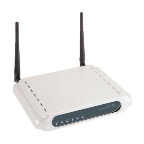
- Page 1 2.4/5.0 GHz IEEE 802.11 Super a+g 108Mbps Wireless LAN Router BLW-54SAG...
-
Page 2: Table Of Contents
Contents Chapter 1. Introduction ....................4 Overview of the BLW-54SAG ................. 4 BLW-54SAG Applications..................4 Package Contents ....................5 The Back Panel ....................... 6 The Front Panel ...................... 7 System Requirements..................... 8 Chapter 2. Connecting the BLW-54SAG ................9 Chapter 3. Configuring the BLW-54SAG ..............11 How to Access the Web-based Utility ..............11... - Page 3 Chapter 4. Upgrading Firmware ..................59 Chapter 5. Specifications ....................60 Chapter 6. Safety Statement ..................61...
-
Page 4: Chapter 1. Introduction
BLW-54SAG Applications 1.2.1 Accessing the Internet The most common use of the BLW-54SAG is to provide shared Internet access to allow everyone on your LAN to surf the web and send/receive emails or files. The BLW-54SAG can automatically ac-quire a public IP address when connecting to the Internet. In turn, it will automatically assign IP ad-dresses to PCs (requesting DHCP client devices) on your LAN - you don’t have to apply for and assign IP addresses to PCs on your network. -
Page 5: Package Contents
BLW-54SAG to provide an 802.11a WLAN environment. Package Contents Please verify that the product package contains all of the following parts. BLW-54SAG Quick Installation Guide CD-ROM (User’s Manual) AC Adapter UTP Cable Stand Warranty Card Please contact your local dealer or distributor if any of the above items is missing. -
Page 6: The Back Panel
The Back Panel The Router’s ports and Reset button are located on the back panel of the Router. RESET Button LAN 1, 2, 3, 4 POWER RESET There are two ways to reset the Router's factory defaults. Either press Button the RESET button, for approximately five seconds, or restore the defaults from the Administration tab - Factory Defaults in the Router's Web-based Utility. -
Page 7: The Front Panel
The Front Panel The Router’s LEDs, which indicate the status of the Router and network activities, are located on the front panel. LAN 1, 2, 3, 4 WLAN-G WLAN-A PPPoE POWER Green. The WAN LED lights up when there is a connection made through the WAN port. -
Page 8: System Requirements
System Requirements Supported Platforms Windows 98/98SE/Me/2000/XP PC equipped with an Ethernet (RJ-45) port MacOS 8.x/9.x/X computer equipped with an Ethernet (RJ-45) port Required Networking Equipment A twisted-pair cable x n (n= the number of computers attached to the product) About Web Configuration Screen The system configuration of the product is adjusted via a Web browser. -
Page 9: Chapter 2. Connecting The Blw-54Sag
Any LAN port on the BLW-54SAG will automatically function as an Uplink port when required. Connect WAN Cable Connect the DSL or Cable modem to the WAN port on the BLW-54SAG. Use the cable supplied with your DSL/Cable modem. If no cable was supplied, use a standard cable. - Page 10 • Power on the Cable or DSL modem. • Connect the supplied power adapter to the BLW-54SAG and power up. Caution: Use only the power adapter provided. Using a different one may cause hardware damage Now that the hardware installation is complete, proceed to Chapter3: Configuring the...
-
Page 11: Chapter 3. Configuring The Blw-54Sag
Chapter 3. Configuring the BLW-54SAG How to Access the Web-based Utility To access the Web-based Utility, launch Internet Explorer or Netscape Navigator, and enter the Router’s default IP address, 192.168.1.1, in the Address field. Then press Enter. A password request page will appear. The first time you open the Web-based Utility, use the default user name admin and default password 0000. -
Page 12: Internet Connection Type
this information can be obtained from your ISP. 3.2.2 Internet Connection Type Choose the type of Internet connection your ISP provides from the drop-down menu. (1) Automatic Configuration - DHCP By default, the Router’s Internet Connection Type is set to Automatic Configuration - DHCP, which should be kept only if your ISP supports DHCP or you are connecting through a dynamic IP address. - Page 13 Internet connections. If you are connected to the Internet through a DSL line, check with your ISP to see if they use PPPoE. If they do, you will have to enable PPPoE. * User Name and Password: Enter the User Name and Password provided by your ISP. * Connect on Demand: Max Idle Time.
- Page 14 ISP will provide you with the IP Address you need to specify here. * Subnet Mask: This is the Router’s Subnet Mask, as seen by users on the Internet (including your ISP). Your ISP will provide you with the Subnet Mask. * Default Gateway: Your ISP will provide you with the Gateway Address.
-
Page 15: Network Setup
(2) MTU MTU is the Maximum Transmission Unit. It specifies the largest packet size permitted for Internet transmission. Select Manual if you want to manually enter the largest packet size that will be transmitted. The recommended size, entered in the Size field, is 1500. - Page 16 (1) DHCP Server DHCP is enabled by factory default. If you already have a DHCP server on your network, or you don’t want a DHCP server, then select Disabled (no other DHCP features will be available). (2) Assign Static DHCP Every time a PC reboots, it is assigned a new local IP address by the Router.
- Page 17 If you want to see a list of DHCP clients, click the DHCP Client Table button. On the DHCP Client Table screen, you will see a list of DHCP clients with the following information: Client Names, Interfaces, IP Addresses, and MAC Addresses. From the To Sort by drop-down menu, you can sort the table by Client Name, Interface, IP Address, or MAC Address.
-
Page 18: The Setup Tab - Ddns
into Internet addresses or URLs. Your ISP will provide you with at least one DNS Server IP Address. If you wish to use another, type that IP Address in one of these fields. You can type up to three DNS Server IP Addresses here. The Router will use these for quicker access to functioning DNS servers. -
Page 19: The Setup Tab - Mac Address Clone
have membership. (2) User Name: Enter the User Name for your DDNS account. (3) Password: Enter the Password for your DDNS account. (4) Host Name: The is the DDNS URL assigned by the DDNS service. (5) Internet: IP Address. This is the Router’s current IP Address as seen on the Internet. (6) Status: This displays the status of the DDNS connection. -
Page 20: The Setup Tab - Advanced Routing
or Cancel to cancel your changes. All of settings are available, after restarting this system. The Setup Tab – Advanced Routing This tab is used to set up the Router’s advanced functions. Operating Mode allows you to select the type(s) of advanced functions you use. Dynamic Routing will automatically adjust how packets travel on your network. - Page 21 network’s layout and exchange routing tables with the other router(s). The Router determines the network packets’ route based on the fewest number of hops between the source and the destination. This feature is Disabled by default. From the drop-down menu, you can also select LAN &...
-
Page 22: The Wireless Tab - Basic Wireless Settings
It is case-sensitive and must not exceed 32 keyboard characters in length. Make sure this setting is the same for all devices in your wireless network. For added security, you should change the default SSID (BLW-54SAG-a) to a unique name. (4) Channel... - Page 23 32 keyboard characters in length. Make sure this setting is the same for all devices in your wireless network. For added security, you should change the default SSID (BLW-54SAG-g) to a unique name. (3) Channel Select the appropriate channel from the list provided to correspond with your network...
-
Page 24: The Wireless Tab - Wireless Security
settings. All devices in your wireless network must broadcast on the same channel in order to communicate. (4) SSID Broadcast When wireless clients survey the local area for wireless networks to associate with, they will detect the SSID broadcast by the Router. To broadcast the Router's SSID, keep the default setting, Enabled. - Page 25 Pre-Shared Key and Pre-Shared Key + RADIUS. Selecta level of WEP encryption, 40/64-bit, 128-bit, or 152-bit. If you want to use a Passphrase, then enter it in the Passphrase field and click the Generate button. If you want to enter the WEP key manually, then enter it in the WEP Key 1-4 field(s).
- Page 26 3.7.3 Wireless-G Settings (1) WEP WEP is a basic encryption method, which is not as secure as the other two methods, Pre-Shared Key and Pre-Shared Key + RADIUS. Select a level of WEP encryption, 40/64-bit or 128-bit.If you want to use a Passphrase, then enter it in the Passphrase field and click the Generate button.
-
Page 27: The Wireless Tab - Wireless Mac Filter
Change these settings as described here and click the Apply button to apply your changes or Cancel to cancel your changes. All of settings are available, after restarting this system. The Wireless Tab - Wireless MAC Filter Wireless access can be filtered by using the MAC addresses of the wireless devices transmitting within your network’s radius. -
Page 28: The Wireless Tab - Advanced Wireless Settings
(1) Wireless Client List Click the Wireless Client MAC List button to display a list of network users by MAC Address. From the To Sort by drop-down menu, you can sort the table by Client Name, Interface, IP Address, MAC Address, or Status. If you want to add any of the wireless clients to the Wireless MAC Filter List, then click the Save to Wireless Client List checkbox and then click the Save Settings button. - Page 29 (1) Authentication Type The default is set to Open System (Default) authentication, when the sender and the recipient do NOT use a WEP key for authentication. With Shared Key authentication, the sender and recipient use a WEP key for authentication. (2) Transmission Rate The rate of data transmission should be set depending on the speed of your wireless network.
- Page 30 The default value is 100. The Beacon Interval value indicates the frequency interval of the beacon. A beacon is a packet broadcast by the Router to synchronize the wireless network. (6) DTIM Interval This value indicates the interval of the Delivery Traffic Indication Message (DTIM). A DTIM field is a countdown field informing clients of the next window for listening to broadcast and multicast messages.
- Page 31 3.9.2 Wireless-G Settings (1) Authentication Type The default is set to Auto (Default), allows either Open System or Shared Key authentication to be used. With Open System authentication, the sender and the recipient do NOT use a WEP key for authentication. With Shared Key authentication, the sender and recipient use a WEP key for authentication.
- Page 32 (4) Transmission Power The greater the transmission power used, the larger the area a wireless network covers. To minimize the likelihood of eavesdropping by unauthorized wireless users, do not use more transmission power than necessary to cover the range needed by your wireless network.
-
Page 33: The Security Tab - Firewall
multiple packets. If you experience a high packet error rate, you may slightly increase the Fragmentation Threshold. Setting the Fragmentation Threshold too low may result in poor network performance. Only minor reduction of the default value is recommended. In most cases, it should remain at its default value of 2346. (10) RTS Threshold Should you encounter inconsistent data flow, only minor reduction of the default value, 2347, is recommended. -
Page 34: The Security Tab - Vpn Passthrough
all, SPI works behind the scenes - automatically - all the time. So you don't have to give it a second thought. This feature is disabled by default. (2) Block Anonymous Requests When enabled, this feature keeps your network from being “pinged,” or detected, by other Internet users. -
Page 35: The Access Restrictions Tab - Internet Access Policy
3.11.1 VPN Passthrough (1) IPSec Passthrough Internet Protocol Security (IPSec) is a suite of protocols used to implement secure exchange of packets at the IP layer. IPSec Pass-Through is enabled by default. To disable IPSec Passthrough, select Disabled. (2) L2TP Passthrough Layer 2 Tunneling Protocol is the method used to enable Point-to-Point sessions via the Internet on the Layer 2 level. -
Page 36: Internet Access Policy
3.12.1 Internet Access Policy (1) Access Policy Access can be managed by a policy. Use the settings on this screen to establish an access policy (after the Save Settings button is clicked). Selecting a policy from the drop-down menu will display that policy’s settings. To delete a policy, select that policy’s number and click the Delete This Policy button. - Page 37 On the Internet Access PCs List screen, you can select a PC by MAC Address or IP Address. You can also enter a range of IP Addresses if you want this policy to affect a group of PCs. After making your changes, click the Save Settings button to apply your changes or Cancel Changes to cancel your changes.
- Page 38 (6) Decide which days and what times you want this policy to be enforced. Select the individual days during which the policy will be in effect, or select Everyday. Then enter a range of hours and minutes during which the policy will be in effect, or select 24 Hours.
-
Page 39: The Applications And Gaming Tab - Port Range Forwarding
3.13 The Applications and Gaming Tab - Port Range Forwarding The Port Range Forwarding screen allows you to set up public services on your network, such as web servers, ftp servers, e-mail servers, or other specialized Internet applications. (Specialized Internet applications are any applications that use Internet access to perform functions such as videoconferencing or online gaming. - Page 40 The preset applications are among the most widely used Internet applications. They include the following: * FTP (File Transfer Protocol): A protocol used to transfer files over a TCP/IP network (Internet, UNIX, etc.). For example, after developing the HTML pages for a website on a local machine, they are typically uploaded to the web server using FTP.
-
Page 41: The Applications & Gaming Tab - Port Range Triggering
workstation console used to oversee the network. The agents return information contained in a MIB (Management Information Base), which is a data structure that defines what is obtainable from the device and what can be controlled (turned off, on, etc.). * Start/End:. -
Page 42: Port Range Triggering
3.14.1 Port Range Triggering (1) Application Name Enter the application name of the trigger. (2) Triggered Range For each application, list the triggered port number range. Check with the Internet application documentation for the port number(s) needed. In the first field, enter the starting port number of the Triggered Range. -
Page 43: The Applications And Gaming Tab - Dmz
3.15 The Applications and Gaming Tab - DMZ The DMZ feature allows one network user to be exposed to the Internet for use of a special-purpose service such as Internet gaming or videoconferencing. DMZ hosting forwards all the ports at the same time to one PC. The Port Range Forwarding feature is more secure because it only opens the ports you want to have opened, while DMZ hosting opens all the ports of one computer, exposing the computer to the Internet. - Page 44 better service to high-priority types of Internet traffic, which may involve demanding, real-time applications, such as videoconferencing. QoS can also prioritize traffic for a specific device or the Router’s LAN ports. 3.16.1 Qos (Quality of Service) There are three types of QoS available, Application Port Priority, MAC Address Priority, and LAN Port Priority.
- Page 45 local machine, they are typically uploaded to the web server using FTP. * Telnet: A terminal emulation protocol commonly used on Internet and TCP/IP-based networks. It allows a user at a terminal or computer to log onto a remote device and run a program.
- Page 46 Select one of these priority levels: Highest, High, Above Normal, or Normal. (3) Port For preset applications, the port number is automatically displayed. For custom applications, enter the appropriate port number in the Port field. (4) Enabled Click the Enabled checkbox to enable QoS for the relevant application. 3.16.3 MAC Address Priority Depending on the settings of the QoS screen, this feature will assign a specific priority for up to five network devices.
-
Page 47: The Administration Tab - Management
(1) Port Number The Router’s LAN port numbers are automatically displayed here. (2) Flow Control For each port, if you want the Router to control the transmission of data between network devices, select Enabled. To disable this feature, select Disabled. (3) Speed This setting limits the speed possible for each port. - Page 48 (1) Router Password and Re-enter to Confirm You can change the Router’s password from here. Enter a new Router password and Re-enter then type it again in the to Confirm field to confirm. 3.17.2 Remote Router Access (1) Remote Management To access the Router remotely, from outside the local network, select Enabled.
-
Page 49: Backup And Restore
3.17.3 UPnP Universal Plug and Play (UPnP) allows Windows Me and XP to automatically configure the Router for various Internet applications, such as gaming and videoconferencing. (1) UPnP If you want to use UPnP, keep the default setting, Enabled. Otherwise, select Disabled. (2) Allow Users to Configure Keep the default setting, Enabled, if you want to be able to make manual changes to the Router while using the UPnP feature. -
Page 50: The Administration Tab - Log
For a permanent record of the Router’s activity logs, Logviewer software must be used. This software can be downloaded from the Planex website, www.planex.net. The Log viewer saves all incoming and outgoing activity in a permanent file on your PC’s hard drive. -
Page 51: The Administration Tab - Diagnostics
The Outgoing Log will display a temporary log of the LAN IP Addresses, Destination URLs or IP Addresses, and Service or Port Numbers for the outgoing Internet traffic. Click the Save the Log button to save this information to a file on your PC’s hard drive. Click the Refresh button to update the log. -
Page 52: The Administration Tab - Factory Defaults
(4) Start to Ping: Click this button to begin the test. A new screen will appear and display the test results. Click the Close button to return to the Diagnostics screen. 3.19.2 Traceroute Test (1) To IP or URL Address: Enter the IP address or URL that you want to ping. (2) Start to Tracert: Click this button to begin the test. -
Page 53: The Administration Tab - Restart
3.21.1 Firmware Upgrade Before upgrading the firmware, download the Router’s firmware upgrade file from www.planex.net the Planex website, . Then extract the file. (1) Please select a file to upgrade In the field provided, enter the name of the extracted firmware upgrade file, or click the Browse button to find this file. -
Page 54: The Status Tab - Router
3.23 The Status Tab - Router The Router screen on the Status Tab displays information about the Router and its current settings. The on-screen information will vary depending on the Internet Connection Type you use. 3.23.1 Router Information (1) Firmware Version: This is the Router’s current firmware. (2) Current Time: This shows the time, based on the time zone you selected on the Setup Tab. -
Page 55: The Status Tab - Local Network
Connection Type. This indicates the type of Internet connection you are using. (1) Login Status The status of the connection is displayed only for a PPPoE connection. For this dial-up style connection, click the Connect button to click if there is no connection and you want to establish an Internet connection. - Page 56 network. (2) Router IP Address: This shows the Router’s IP Address, as it appears on your local, Ethernet network. (3) Subnet Mask: When the Router is using a Subnet Mask, it is shown here. 3.24.2 DHCP Server (1) DHCP Server The status of the Router’s use as a DHCP server is displayed here.
-
Page 57: The Status Tab - Wireless
3.25 The Status Tab - Wireless The Wireless screen on the Status Tab displays the status of your Wireless-A and/or Wireless-G networks. 3.25.1 Wireless-A Information (1) MAC Address: This is the Router’s MAC Address, as seen on your local, wireless network. - Page 58 wireless network is broadcasting. (5) Security: As selected on the Wireless Security tab, this displays the wireless security method used by the Router. (6) SSID Broadcast: As selected on the Wireless tab, this displays the status of the Router’s SSID Broadcast feature. 3.25.2 Wireless-G Information (1) MAC Address: This is the Router’s MAC Address, as seen on your local, wireless network.
- Page 59 After you upgrade its firmware, you will have to re-enter all of your configuration settings. To upgrade the Router’s firmware, follow these instructions: Download the firmware from Planex's website at www.planex.net. Then extract the firmware file. Click Firmware Upgrade from the Web-Utility's Administration tab, and the Upgrade Firmware screen will appear.
-
Page 60: Specifications
Chapter 5. Specifications Model BLW-54SAG Standards IEEE 802.3, IEEE 802.3u, IEEE 802.11a, IEEE 802.11g, IEEE 802.11b Ports WAN: One 10/100 RJ-45 Port for Cable/DSL Modem LAN: Four 10/100 RJ-45 Switched Ports One Power Port Button One Reset Button Cabling Type... - Page 61 Chapter 6. Safety Statement CE Statements This device has bee tested and found to comply with the requirements set up in the council directive on the approximation of the law of member states relating to EMC Directive 89/336/EEC, Low Voltage Directive 73/23/EEC and R&TTE Directive 99/5/EC. FCC Safety Statements This device complies with Part 15 of the FCC rules.
Need help?
Do you have a question about the BLW-54SAG and is the answer not in the manual?
Questions and answers