Table of Contents
Advertisement
Quick Links
Advertisement
Table of Contents

Related Manuals for Planex eXgate Series


Summary of Contents for Planex eXgate Series
- Page 1 Series Multi-Use Wireless VPN Router BRC-14V / BRC-W14V...
- Page 3 User's Manual eXgate Series Multi-Use Wireless VPN Router BRC-14V / BRC-W14V...
- Page 4 Please Read Before Using the Product ■ Objective Thank you for your purchase of PLANEX product. This document shows you how to use the product properly. Please keep it in a safe place so that you can view it whenever necessary.
- Page 5 Important Safety Instructions Before using the product, be sure to read and adhere to the following safety guidelines. Hazardous conditions including electric shock, fire or product failure may result if these guidelines are not followed. Such hazardous conditions may cause death or serious injury to the user.
- Page 6 Installation and Storage Do not use the product in locations that do not meet the operating or environmental requirements of the product. The use of the product in environments that do not meet the operating temperature/ humidity requirements may result in hazardous conditions including electric shock or fire, or product failure and/or malfunctioning.
- Page 7 Miscellaneous Please be sure to back up the data of your computer regularly, whether or not it is used with the product. By backing up data, you can restore the data even when the main data media (HDD, etc.) fails. Note that we are not responsible for any loss of data and other damage that occurs while the product is in use.
-
Page 8: Table Of Contents
Chapter 1 ........................10 Introduction ........................10 Overview........................10 Key Features ......................11 Verifying Package Contents..................15 Parts Terminology ...................... 16 System Requirements ....................19 Initializing Configuration..................20 Chapter 2 ........................22 Hardware Installation....................22 Installation Site ......................22 Installing Hardware ....................23 Connecting the Product to an ADSL/Cable Modem.......... - Page 9 Enabling Multi-Session via an external DSL Connection........68 Registering multiple ISP connections ............69 ■ Changing connection priority ............... 71 ■ Configuring Unnumbered Connection ..............76 Configuring Unnumbered Connection via PPPoE Connection ........ 78 Configuring Unnumbered Connection via Non-PPPoE Connection ......81 Configuring IP Address of Your PC ................
-
Page 10: Chapter 1
Chapter 1 Introduction Overview The BRC-W14V is a multi-use VPN router equipped with hardware-based VPN function. The router supports high-speed Internet connection services including FTTH and CATV, and it utilizes IXP 422-266Mhz network processor from Intel as its CPU to achieve much faster processing speed than conventional routers. Furthermore, the product's built-in IEEE802.11g compliant wireless LAN function lets you establish a wireless network that seamlessly incorporates an existing wired (fixed-line) network. -
Page 11: Key Features
Key Features On-board IXP-422 266MHz processor High-speed routing achieved via Intel's high performance network processor IXP422-266MHz Hardware-based VPN Functionality The product supports IPSec, PPTP Server and PPTP client features. The router achieves high-speed VPN approaching approximately 42Mbps when IPSec (3DES) is in use. Built-in USB Port The on-board USB port enables system extensibility as it supports option USB camera and USB storage. - Page 12 LAN side IP address The LAN side IP address of the product is 192.168.1.1, and it can be manually adjusted to another address which best suits your networking environment. NAPT Multiple private addresses are converted to one global address. This feature allows multiple PC's on the LAN side to easily connect to the Internet.
- Page 13 Security Level The 3-level security system of the product allows you to easily set up security function. The configuration can be customized as needed to let you flexibly configure LAN-to-Internet as well as Internet-to-LAN security settings. Packet Filtering The packet filtering function of the router blocks or allows passage of packets sent/received by the product in accordance with predefined rules.
- Page 14 Local Server Servers and services on the LAN side can be made publicly accessible from the WAN side. When Local Server function is enabled, access (packets) from the WAN side are transferred to a designated PC on the LAN side Virtual Computer This feature allows a PC on the LAN side to be publicly accessible from the WAN side.
-
Page 15: Verifying Package Contents
Verifying Package Contents Please verify that the product package contains all of the following parts. . BRC-W14V AC adapter for BRC-W14V Vertical stand UTP straight-through LAN cable (1m) Short cord User's manual (this document with warranty note) Reference manual (CD-ROM) Please contact our technical support if any of the above components is missing. -
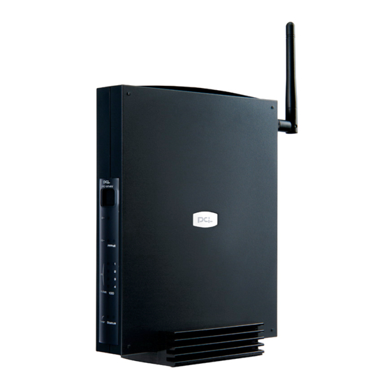
Page 16: Parts Terminology
Parts Terminology ■ Front View 【LED Status】 Yellow Flashing Booting the product Power LED Green The boot process was successful The power is on Status LED Green The power is off There is a 100M link on LAN port LAN 100 LED Green There is a 10M link on LAN port Active connection on LAN port... - Page 17 ■ Rear View...
- Page 18 ■ Back View...
-
Page 19: System Requirements
System Requirements ■ Supported Platforms Windows 98/98SE/Me/2000/XP PC equipped with an Ethernet (RJ-45) port MacOS 8.x/9.x/X computer equipped with an Ethernet (RJ-45) port ■ Required Networking Equipment A twisted-pair cable x n (n= the number of computers attached to the product) ■... -
Page 20: Initializing Configuration
Initializing Configuration In case you forget the IP address and password of the product OR configure incorrect values and the configuration screen is not accessible, you can initialize the system configuration to restore the factory-default settings of the router. Caution: Please note that all the parameters configured prior to initialization will be deleted. -
Page 22: Chapter 2
Chapter 2 Hardware Installation This chapter describes installation procedure of the BRC-W14V as well as procedure to attach an ADSL/cable modem and PC's to the router. Installation Site Please strictly follow the instructions below when installing the product. Do not install the product in a damp place. Avoid exposure to direct sunshine, any heat source or dust. -
Page 23: Installing Hardware
Installing Hardware ■ Connecting the AC Power Adapter Attach the DC jack plug of the supplied AC power adapter to the DC power jack on the product. Do not attach the other end of the AC power adapter to wall outlet yet. ■... - Page 24 ■ Horizontal Installation Install the product so that the flat surface of the product faces downward.
-
Page 25: Connecting The Product To An Adsl/Cable Modem
Connecting the Product to an ADSL/Cable Modem ■ Before connecting your modem Turn off the power of your ADSL/Cable modem. If your modem does not have an ON/OFF switch, remove its AC adapter from wall outlet. Please use the twisted-pair cable supplied with this product. ■... - Page 26 ■ Connecting a cable modem Use a LAN cable to connect the WAN port on the product to the Ethernet port on your cable modem.
-
Page 27: Connecting The Product To A Pc
Connecting the Product to a PC The LAN ports on the router supports Auto MDI/MDI-X, a function that automatically detects the straight-through and crossover cable types. Be sure to have a twisted-pair cable ready beforehand for each PC attached to the product. Attach one end of the twisted-pair cable to one of the LAN ports on the product. -
Page 28: Connecting The Power Adapter To The Product
Connecting the Power Adapter to the Product Attach the AC power adapter to wall outlet and turn on the power of the product. Check the LED status to verify that communication is taking place normally. Should you detect any difficulty attaching the AC power adapter directly to the wall outlet, attach the supplied short cord to the AC power adapter. - Page 29 The product is turned on at this moment. Verify the status of the LED's below: Normal Status Power LED Flashes in orange right after the AC adapter is attached to the wall Status LED outlet, then glows in green after the product has booted WAN LED...
-
Page 30: Chapter 3
Chapter 3 Configuring a PC This chapter describes how to verify and adjust the network setting of your PC to connect to the Internet via the router. There is a specific procedure to make this adjustment for each OS, and the changes below need to be made on every PC attached to the router. -
Page 31: Adjusting Network Configuration Of Your Pc
Adjusting network configuration of your PC ■ Windows XP Caution You need to be the administrator of your PC or need to log on as a user with equivalent access right. The configuration steps and screen images below are intended for default Windows XP OS settings. - Page 32 4. The Local Area Connection Properties screen will be displayed. Select [Internet Protocol (TCP/IP)], then click [Properties]. 5. The [Internet Protocol (TCP/IP) Properties] screen will be displayed. Check [Obtain an IP address automatically] and [Obtain DNS server address automatically], then click [OK].
- Page 33 6. The [Local Area Connection Properties] screen will be displayed again. Click on [OK].
-
Page 34: Windows2000
■ Windows2000 Caution You need to log on as Administrator or user with equivalent access right. 1. Select [Start] - [Settings] - [Control Panel]. 2. Control Panel will be displayed. Double-click [Network] icon. 3. [Network] screen will be displayed. Right-click [Local Area Connection], then click [Properties]. - Page 35 4. [Local Area Connection Properties] screen will be displayed. Select [Internet Protocol (TCP/IP)] and then click [Properties]. 5. [Internet Protocol (TCP/IP) Properties] screen will be displayed. Check [Obtain an IP address automatically] and [Obtain DNS server address automatically], then click [OK]. 6.
-
Page 36: Windows Me/98Se/98
■ Windows ME/98SE/98 1. Select [Start] - [Settings] - [Control Panel]. 2. The [Control Panel] screen will be displayed. Double-click the [Network] icon. Should the Network Icon be invisible under Windows Me, click on the [Display ※ all control panel options] item on the left side of the control panel. 3. - Page 37 4. The [TCP/IP Properties] screen will be displayed. Click on the [IP Address] tab, then check [Obtain an IP address automatically]. 5. Click on the [Gateway] tab and verify that no entries are shown in the [Installed gateways] window. Caution If an IP address is shown in the window above, select that address (entry) and click on the [Remove] button.
- Page 38 6. Click on the [DNS Configuration] tab, and select [Disable DNS]. Click [OK]. 7. The [Network] screen will be displayed again. Click [OK]. 8. When the OS asks if you want to restart computer now, click [Yes] to restart the system.
-
Page 39: Mac Os X
■ Mac OS X The appearance of set up screen may vary depending on the Mac OS version you ※ are using. 1. From Apple menu, select [System Preferences]. 2. The [System Preferences] screen will be displayed. Click on the [Network] icon. If the [Network] icon is not visible at this moment, click the [Show All] icon on ※... -
Page 40: Mac Os 9.X/8.X
■ Mac OS 9.x/8.x The appearance of setup screen may vary depending on the MacOS version you ※ are using. 1. From Apple menu, select [Control Panels] - [TCP/IP]. 2. The [TCP/IP] window will be displayed. Select [Ethernet] in the [Connect via] field, then select [Using DHCP Server] in the [Configure] field. -
Page 41: Verifying Connection Between The Product And Your Pc
Verifying connection between the Product and your PC Follow the steps below to verify that a valid IP address has been assigned to your computer. Caution The DHCP server function of the router is enabled by default, and an IP address is automatically assigned to each computer attached to it. - Page 42 3. The [Network Connections] window will be displayed. Right-click on the [Local Area Connection], then click [Properties]. 4. The [Local Area Connection Properties] window will be displayed. Click the [Support] tab and verify the IP address shown in the [IP Address] field is 192.168.1.x where x is a number other than 1.
-
Page 43: Windows2000
■ Windows2000 1. Select [Start] - [Programs] - [Accessories] - [Command Prompt]. 2. The [Command Prompt] window will be displayed. After [C:\>], enter [ipconfig] (without brackets) and press the Enter key. 3. [Ethernet adapter Local Area Connection] information will be displayed. Verify that the IP address shown in the [IP Address] field is 192.168.1.x where x is a number other than 1. -
Page 44: Windows Me/98Se/98
■ Windows ME/98SE/98 1. Select [Start] -[Run]. 2. Now type [winipcfg] and click [OK]. 3. The [IP Configuration] window will be displayed. In the [Ethernet Adapter Information] section, select the LAN card/board you are using. 4. Verify that IP address is 192.168.1.x where x is any number other than 1. Caution If another IP address is shown in the field, click on the [Release] button and then click [Renew]. -
Page 45: Mac Os X
■ Mac OS X ※The appearance of set up screen may vary depending on the Mac OS version you are using. 1. From Apple menu, select [System Preferences]. 2. The [System Preferences] screen will be displayed. Click on the [Network] icon. ※If the [Network] icon is not visible at this moment, click the [Show All] icon on the left. -
Page 46: Mac Os 9.X/8.X
■ Mac OS 9.x/8.x ※The appearance of setup screen may vary depending on the MacOS version you are using. 1. From Apple menu, select [Control Panels] - [TCP/IP]. 2. The [TCP/IP] window will be displayed. Select [Ethernet] in the [Connect via] field, and verify that the IP address shown in the [IP Address] field is 192.168.1.x where x is a number other than 1. -
Page 47: Chapter 4
Chapter 4 Connecting to the Internet To modify the system configuration of the product, open the management console of the product using a standard Web browser (see below). If this is the first time to connect to the Internet using the BRC-W14V, click on [Connection Wizard] icon on the left of the configuration screen. - Page 48 1. Using a computer that is already attached to the BRC-14V, start a Web browser and enter "http://192.168.1.1 "or " http://brc-14v.home/" in the address field. 2. The first time login page will be displayed. Click [OK]. 3. [Login Setup] page will be displayed. Specify the login user name and login password to access the management console.
- Page 49 4. Click [OK]. 5. The management console will be displayed. ■ Using Connection Wizard The following sections describe the procedure to connect to the Internet using an [External DSL Modem] or [Ethernet Connection] via the management console. Select one of the four connection methods that best matches the connection scheme required in your network, and move to the corresponding section in this chapter.
-
Page 50: Using An External Dsl Modem
Using an external DSL modem This section describes the procedure to configure the product via an external DSL modem. Please be sure to obtain your account information from your ISP in advance. 1. Click on [Connection Wizard] icon on the side bar. 2. - Page 51 ISP and enter [Login User Name] and [Login Password]. [Login User Name] Enter the alphanumeric user name/user account name provided by your ISP. Be sure to enter the entire name (ex. brc@planex.co.jp). [Login Password] Enter the password provided by your ISP (case sensitive). The characters entered will be displayed as asterisks ("*").
- Page 52 6. [Connection Summary] page will be displayed. Verify that the information you entered is correct and click [Finish]. 7. [Network Map] page will be displayed. Verify that an external DSL cable connection has been created, then click [Network Connections] on the side bar. 8.
- Page 53 ① Click on [Network Connections] icon on the side bar. ② [Network Connections] page will be displayed. Click on the <modify> button for [WAN Ethernet] connection. ③ [WAN Ethernet Properties] page will be displayed. Click on the [Disable] button to disconnect the current connection to the Internet.
- Page 54 ④ The management console will prompt for your confirmation to disconnect from the Internet. Click [OK]. ⑤ [WAN Ethernet Properties] page will be displayed again. Verify that [Status] is now [Disabled], and click on the [Settings] button. ⑥ [Configure WAN Ethernet] page will be displayed. In the [DNS Server] field, select [Use the following DNS server addresses] and enter the IP addresses provided from your ISP to [Primary DNS Server] and [Secondary DNS Server] fields respectively.
- Page 55 ※ If only one DNS server address has been provided by your ISP, enter the address in the [Primary DNS Server] field. ⑦ [WAN Ethernet Properties] page will be displayed again. Click on the [Enable] button. ⑧ Verify that [Status] is now [Up]. Click [OK]. ⑨...
-
Page 56: Assigning A Static Ip Address Using An External Dsl Modem
Assigning a Static IP Address using an external DSL modem 1. Click [Network Connections] on the side bar. 2. [Network Connections] page will be displayed. Click on the <modify> button for [WAN Ethernet] connection. 3. [WAN Ethernet Properties] page will be displayed. Click on the [Disable] button to disconnect from the Internet. - Page 57 4. The management console will prompt for your confirmation to disconnect from the Internet. Click [OK]. 5. [WAN Ethernet Properties] page will be displayed again. Verify that [Status] is now [Disabled], and click on the [Settings] button. 6. [Configure WAN Ethernet] page will be displayed. In the [Internet Protocol] field, select [Use the following IP addresses] and enter the IP address provided by your ISP.
- Page 58 7. Click [OK]. 8. [WAN Ethernet Properties] page will be displayed. Click on the [Enable] button. 9. Verify that [Status] is now [Up]. Click [OK]. 10. The connection setup is now complete.
-
Page 59: Deleting An External Dsl Modem Connection
Deleting an External DSL Modem Connection Follow the steps below to delete an existing PPPoE (external DSL modem) connection. NOTE: Only the PPPoE connection you have created may be deleted (the default. connection name ("WAN Ethernet") cannot be deleted). 1. Click [Network Connections] icon on the side bar. 2. - Page 60 4. [Network Connections] page will be displayed again. The selected connection is now disabled. 5. The deletion of PPPoE connection is now complete.
-
Page 61: Automatic Ip Assignment Via Ethernet Connection
Automatic IP Assignment via Ethernet Connection This section describes the procedure to automatically obtain an IP address without using an external DSL cable modem connection. ※ Non-cable modem connection services (Ethernet connections) include i)automatic IP address assignment via standard connection or DHCP as well as ii)static IP address assignment. - Page 62 3. [Internet Connection] page will be displayed. Select [Ethernet Connection] and click [Next]. 4. [Ethernet Connection] page will be displayed. Select [Dynamic Negotiation] and click [Next]. 5. [Connection Summary] page will be displayed. Verify the new settings, and click [Finish]. The product will now automatically obtain an IP address from your ISP. 6.
- Page 63 ※If no DNS server IP address has been specified by your ISP, simply skip Step ① through ⑨ below. ① Click on [Network Connections] icon on the side bar. ② [Network Connections] page will be displayed. Click on the <modify> button for [WAN Ethernet] connection.
- Page 64 ④ The management console will prompt for your confirmation to disconnect from the Internet. Click [OK]. ⑤ [WAN Ethernet Properties] page will be displayed again. Verify that [Status] is now [Disabled], and click on the [Settings] button. ⑥ [Configure WAN Ethernet] page will be displayed. In the [DNS Server] field, select [Use the following DNS server addresses] and enter the IP addresses provided from your ISP to [Primary DNS Server] and [Secondary DNS Server] fields respectively.
- Page 65 ⑦ [WAN Ethernet Properties] page will be displayed again. Click on the [Enable] button. ⑧ Verify that [Status] is now [Up]. Click [OK]. ⑨ The connection setup is now complete.
-
Page 66: Assigning A Static Ip Address Via Ethernet Connection
Assigning a Static IP Address via Ethernet Connection This section describes how to assign a static IP address without using an external DSL modem connection. 1. Click [Connection Wizard] from the side bar. 2. [Connection Wizard] page will be displayed. Select [Internet Connection] and click [Next]. - Page 67 4. [Ethernet Connection] page will be displayed. Select [Manual IP Address Configuration] and click {Next}. 5. [Manual IP Address Configuration] page will be displayed. Refer to the information provided by your ISP, and enter IP address, subnet mask, default gateway and DNS server addresses.
-
Page 68: Enabling Multi-Session Via An External Dsl Connection
Enabling Multi-Session via an external DSL Connection The product supports PPPoE (external DSL connection) multi-session. When multi-session is in use, you can register multiple ISP accounts on the product and use up to four sessions simultaneously. When multiple ISP's are registered, you can freely change default gateway or the connection priority among the ISP's. -
Page 69: Registering Multiple Isp Connections
■ Registering multiple ISP connections This section describes the procedure to add a second PPPoE (external DSL) connection. (It is assumed that the first PPPoE connection has already been registered.) 1. Click [Connection Wizard] on the side bar. 2. [Connection Wizard] page will be displayed. Select [Internet Connection] and click [Next]. - Page 70 4. [External DSL Modem] page will be displayed. Refer to the information provided by your ISP, and enter the login user name and password of the second ISP. Click [Next]. 5. [Connection Summary] page will be displayed. Verify the information displayed, and click [Finish].
-
Page 71: Changing Connection Priority
■ Changing connection priority When multiple PPPoE (external DSL modem) connections are created, the connection priority of each entry is set in the order of its creation. (Ex. First connection has the highest connection priority and the most recently created connection has the lowest priority, etc.) You can freely change the connection (priority) order and default gateway after creating PPPoE connections. - Page 72 2. [Network Connections] page will be displayed. Click on the <modify> button for [WAN PPPoE]. 3. [WAN PPPoE Properties] page will be displayed. If the connection is currently active, click [Disable] to disconnect from the Internet. Click [Settings]. 4. [Configure WAN PPPoE] page will be displayed. Enter "21" in [Device Metric] field and click [OK].
- Page 73 5. [WAN PPPoE Properties] page will be displayed again. Click the [Enable] button, and verify that [Status] is now [Up]. Click [OK]. 6. [Network Connections] page will be displayed again. Click on the <modify> button for [WAN PPPoE2]. 7. [WAN PPPoE2 Properties] page will be displayed. If there is an active connection, click on the [Disable] button to disconnect from the Internet.
- Page 74 8. [Configure WAN PPPoE2] page will be displayed. Enter "20" in the [Device Metric] field and click [OK]. 9. [WAN PPPoE2 Properties] page will be displayed again. Click on the [Enable] button and verify that [Status] is now [Up]. Click [OK]. 10.
- Page 75 11. [WAN PPPoE Properties] page will be displayed. Click on the [Enable] button and verify that [Status] is now [Up]. Click [OK]. 12. Now the product is connected to the Internet using [WAN PPPoE2] as its default gateway and [WAN PPPoE] as second preferred connection. 13.
-
Page 76: Configuring Unnumbered Connection
Configuring Unnumbered Connection The product supports "unnumbered connection" that allows you to use multiple static IP addresses. This function lets you make servers (and other devices) on your LAN publicly accessible on the Internet. You can also configure i)NAPT-based private address host as well as ii) global address host (enabled via unnumbered connection) and establish connection to both hosts simultaneously. - Page 77 The procedure to configure unnumbered connection via PPPoE (external DSL modem) connection differs from that utilizing a non-PPPoE connection. Please verify the type of Internet connection you are using, and refer to one of the two sections below. Using unnumbered connection via PPPoE (external DSL modem) connection ->...
-
Page 78: Configuring Unnumbered Connection Via Pppoe Connection
Configuring Unnumbered Connection via PPPoE Connection Follow the steps below to configure unnumbered connection via PPPoE (external DSL modem) connection. 1. Click [Network Connections] icon on the side bar. 2. [Network Connections] page will be displayed. Click on the <modify> button for [WWW PPPoE] connection that has been created previously. - Page 79 4. [Configure WAN PPPoE] page will be displayed. In the [Internet Protocol] field, select [Use the following IP addresses]. 5. In the [IP Address] field, enter the IP address provided by you ISP Similarly, enter the DMZ network address and subnet mask provided by your ISP under the [DMZ Network (Unnumbered)] section.
- Page 80 7. [WAN PPPoE Properties] page will be displayed again. Click on the [Enable] button and verify that [Status] is now [Up]. Click [OK]. 8. The WAN-side configuration of unnumbered connection is now complete. proceed to Section 4-11 [Configuring IP Address of your PC] to assign a global IP address to your computer.
-
Page 81: Configuring Unnumbered Connection Via Non-Pppoe Connection
Configuring Unnumbered Connection via Non-PPPoE Connection Follow the steps below to configure unnumbered connection using a non-PPPoE connection. 1. Click on the [Network Connections] icon on the side bar. 2. [Network Connections] page will be displayed. Click on the <modify> button for [WAN Ethernet] connection. - Page 82 4. In the [Internet Protocol] field, select [Use the Following IP Addresses] and enter the information provided by your ISP. Similarly, enter the DMZ network address and subnet mask provided by your ISP under the [DMZ Network (Unnumbered)] section. Click [OK]. 5.
-
Page 83: Configuring Ip Address Of Your Pc
Configuring IP Address of Your PC This section provides the procedure for assigning a global IP address to your computer. (The steps shown below are for Windows2000.) 1. Select [Start] - [Settings] - [Control Panel]. 2. Double-click [Network and Dialup Connections] icon. 3. - Page 84 4. Select [Internet Protocol (TCP/IP)] and click on the [Properties] button. 5. Select [Use the following IP address] and [Use the following DNS server address] options. Refer to the information provided by your ISP, and enter IP address, subnet mask, default gateway, primary DNS server and secondary DNS server addresses. ※...
-
Page 85: Networking Q&A
Appendix A Networking Q&A Questions regarding the broadband router Due to the rapid diffusion of the Internet, an increasing number of people are now using broadband routers (“Broadband Routers”) quite commonly. This section lists most frequently asked questions on networking as well as the use of our products. Please take a minute to go over this section if you are uncertain about networking. - Page 86 no need to access the Internet (or cable modem, etc) at this point. Q. What is a browser? A. It is an application used to view home pages (web sites) on the Internet. Well-known browsers include Internet Explorer and Netscape. <Supplementary Note>...
-
Page 87: Management Console
Management Console This section provides frequently asked questions on how to access the management console. Please check whether your computer exhibits any of the symptoms below. Q. How come I cannot access the management console? A. Check whether the LAN LED, IP address, proxy and security application settings have been configured correctly. - Page 88 the management console of the Broadband Router. Verifying the IP address of your computer Follow one of the sections below that corresponds to your OS to verify the IP address already assigned to your computer. Windows ® 95/98/ME: 1. Select [Start] – [Run], then enter “WINIPCFG”. Click on the OK button. 2.
-
Page 89: Using The Ping Command
x is a number other than 1. ■ Using the Ping Command Is there a valid communication link between your computer and the Broadband Router? How to verify the communication link between the two devices (Windows ® only) You can use the ping command to check whether a valid link is established between your computer and the Broadband Router. -
Page 90: Checking The Proxy Configuration Of Your Browser
3. The “Pinging 192.168.1.1 with..” message will be displayed four to five times. There is a valid link if the “Reply from 192.168.1.1…” message is displayed. The response is “Request Timed Out” If the response to the [ping 192.168.1.1] command is [Request Timed out], there is a chance that either a valid IP has not been obtained or the LAN adapter of computer is not functioning properly. - Page 91 2. Select [Advanced] – [Proxies] and check [Direct connection to the Internet]. 3. Click on the [OK] button to close the window. 4. Exit and restart Netscape and check whether you can access the management console page of the Broadband Router. The influence of Security Applications The latest version of anti-virus applications including PC-Cillin and Norton Anti Virus are equipped with simple firewall function.
-
Page 92: Failure To Connect To The Internet
Failure to connect to the Internet This section describes what to check and how to do it when you cannot access the Internet after configuring the Broadband Router correctly. Each subsection below is dedicated to a specific connection method/type. Please review the subsection that is appropriate for your network. -
Page 93: Using Cable Connection
■ Using Cable Connection Q. What are the points to be checked when connecting to the Internet via cable services? A. Check the method of obtaining IP address as well as cable connection procedure. ■ IP Address Assignment When a cable service is used, the connection to the Internet is established through a method called “normal (DHCP) connection”. -
Page 94: Last Points To Check
Connect to a homepage using its IP address. In the address field/bar of your browser, enter http://210.197.75.205 and press the Enter key to see whether our (PLANEX) web site can be accessed. If http://210.197.75.205 can but http://www.planex.co.jp cannot access the page, there is a chance that the DNS server address has not been configured correctly. -
Page 95: Other Faq's
DNS server address specified by your ISP. Your computer cannot access home pages via their domain names (ex. www.planex.co.jp) unless this address is configured correctly. Q. The computers attached to the Broadband Router cannot communicate with each other. - Page 96 Verifying Communication via the Broadband Router Refer to the [How come I cannot access the management console?] section to review the methods to verify currently assigned IP address and how to use the ping command, use the command to ping the other PC. If the [Reply from..] response is shown, the PC-to-PC connection is working.
-
Page 97: Specifications
Appendix B Specifications Items Description Product Name Multi-Use Wireless VPN Router Model Number BRC-W14V 10/100BASE-TX Auto-Negotiation Port x 1 WAN Port (RJ-45 Connector) Supports IEEE802.3, Network IEEE802.3u, AutoMDI/MDI-X Configuration 10/100BASE-TX Auto-Negotiation Port x 4 LAN Ports (RJ-45 Connector) Supports IEEE802.3, IEEE802.3u, AutoMDI/MDI-X Standards IEEE802.11b ARIB STD-T66... - Page 98 MENO...
- Page 99 MENO...
- Page 100 Function Reference...
- Page 101 LAN Side Configuration This chapter describes how to configure the LAN-side parameters of the product. IP Address Configuration This section describes how to verify and modify IP address of LAN port(s) on the product. !Caution Please be sure to assign a valid IP address to the product. Assigning an incorrect or invalid address to it may result in failure to connect to the Internet.
- Page 102 Verifying and modifying LAN port IP address The factory default LAN port IP address of the product is 192.168.1.1. Follow the steps below tf you need to assign another IP address to the LAN port. (ex. the product is installed in an existing LAN, etc). Click on [Network Connections] icon on the side bar.
- Page 103 Click on the [OK] button at the bottom of the page. [LAN Ethernet Properties] page will be displayed again. ※If [Attention] page is displayed after clicking on the OK button, verify the information displayed and click [OK]. [LAN Ethernet Properties] page will be displayed. Click [OK].
- Page 104 NAPT (IP Masquerading) The router supports NAPT as its routing mode. NAPT (also known as IP masquerading) converts multiple private IP addresses to one global IP address. This function is used when i)there are multiple PC’s on the LAN side with private IP address and ii) all the PC’s need to connect to the Internet via a single global IP address.
- Page 105 DHCP Server Configuration The built-in DHCP server function automatically assigns a unique IP address to every PC or networking device in the network as it is connected to the LAN. The DHCP server function of the product can also be configured to always assign a static IP address to a specific PC.
- Page 106 Basic configuration of DHCP server This section describes the basic configuration of DHCP server settings. 1. Click on the [Advanced] icon on the side bar. 2. Click on the [IP Address Distribution] icon. 3. The subnet and dynamic IP range of DHCP server will be displayed. To modify any of the values, click on the <modify>...
- Page 107 4. [DHCP Settings for LAN Ethernet] window will be displayed. Enter the range IP addresses to be assigned, subnet mask and least time. Click [OK]. [DHCP Server] Enables DHCP server function [Start IP Address] Enter the first IP address to be assigned [End IP Address] Enter the last IP address to be assigned [Subnet Mask]...
- Page 108 Assigning a static IP address via DHCP server This section provides the procedure to configure the DHCP server function to always assign a static IP address to a specific PC or network device. 1. Click on the [Advanced] icon on the side bar. 2.
- Page 109 4. Click on the <Add> button in the [New Static Connection] field. 5. Enter the host name, IP address and MAC address of the PC or network device to add, then click [OK]. [Host Name] Enter the host name of the PC or network device to add (1-63 alphanumeric characters) [IP Address] Enter the IP address you wish to assign to the new PC or network device.
- Page 110 6. Verify that the host you added is now listed in the [DHCP Connections] window. 7. The DHCP function setup is now complete.
- Page 111 Changing IP Address This section describes the procedure to change the configuration of PC or network device to which IP address is automatically assigned via DHCP server. 1. Click on the [Advanced] icon on the side bar. 2. Click on [IP Address Distribution] icon. 3.
- Page 112 4. Click on the <modify> button for the host entry for which you wish to change configuration. 5. Select [Static lease type] and click on [OK]. 6. Verify that lease type is [Static], then click the <modify> button for the host. 7.
- Page 113 Deleting IP Address This section describes how to delete a registered IP address and host associated with the address. 1. Click on [Advanced] on the side bar. 2. Click on [IP Address Distribution]. 3. Click on the [Connection List] button.
- Page 114 4. Click on the <delete> button for the host you wish to delete. 5. Click on the [Close] button. [IP Address Distribution] window will be displayed again. 6. The IP deletion is now complete.
- Page 115 Enabling and disabling DHCP server The section below describes how to enable or disable the built-in DHCP server function. 1. Click on [Advanced] on the side bar. 2. Click on [IP Address Distribution]. 3. The current DHCP server subnet and the range of IP addresses being assigned will be displayed.
- Page 116 4. Select [DHCP Server] in the [IP Address Distribution] field to enable the function, or select [Disabled] to disable it. Caution! If you have disabled DHCP server, be sure to manually assign an IP address to each PC or network device attached to the LAN side of the product. 5.
- Page 117 DNS Server Configuration The built-in DNS server of the product manages the IP-to host (PC or network device in LAN) association data. DNS server refers to the same association table used by DHCP server. Once a host name is registered during DHCP server configuration, the host name and its associated IP address will be automatically managed by DNS server.
- Page 118 Verifying host name and IP address via DHCP server The built-in DNS server of the product refers to the same association table used by DHCP server. DNS server thus reflects host names and IP addresses entered via DHCP server. This section provides a procedure to verify host name and IP address registered via DHCP server function.
- Page 119 3. Click on the [Connection List] button. 4. The built-in DHCP server will display the host names and IP addresses already registered. 5. Click on the [Close] button to return to the [IP Address Distribution] window. 6. Click on the [Close] button to return to the [Advanced] window. 7.
- Page 120 8. The host names and IP addresses already registered to the built-in DNS server will be displayed. 9. The verification of IP and host name is now complete.
- Page 121 Manual registration of host name and IP address When DHCP server function is not in use, host name and IP address need to be registered manually. 1. Click on the [Advanced] icon on the side bar. 2. Click on the [DNS Server] icon. 3.
- Page 122 4. Enter the host name and IP address you wish to register to DNS server, then click [OK]. 5. The manual addition of host name and IP address is now complete.
- Page 123 Modifying host name and IP address After changing host name or IP address, the information previously registered to DNS server needs to be manually modified as well. !Caution If DHCP server function is enabled, DNS server will automatically reflect changes made to PC host names.
- Page 124 4. Modify host name and IP address as necessary and click [OK]. ※ As for hosts whose IP addresses are automatically assigned by DHCP server, only their host name may be changed. 5. The manual configuration of host name and IP address is now complete.
- Page 125 Deleting host name and IP address Follow the steps below to delete previously registered host name or IP address. 1. Click on the [Advanced] icon on the side bar. 2. Click on the [DNS Server] icon. 3. Click on the <delete> button for the host name you wish to delete, then click [OK]. 4.
- Page 126 Proxy DNS The product is equipped with a proxy DNS function. When each PC on the LAN side attempts to make a connection to a specific domain name on the Internet (DNS inquiry), proxy DNS forwards the inquiry to a DNS server on the Internet and returns the corresponding IP address to the PC.
- Page 127 Routing Configuration The product supports RIP, RIP Version 2 as dynamic routing protocols. It supports static routing as well. Configuring dynamic routing This section describes how to configure dynamic routing and dynamically register routing information. Specify an interface on which dynamic routing is enabled, then enable dynamic routing on the product.
- Page 128 5. Select [Routing Information Protocol (RIP)] in the [Device Metric] section. 6. Now configure RIP receive/transmit settings. Select the type of RIP the product receives in the [Listen to RIP Messages] field. Similarly, select the type of RIP that the product transmits in the in the [Send RIP Messages] field.
- Page 129 7. Click [OK]. If a warning window appears, verify the displayed information and click on the [OK] button. 8. [LAN Ethernet Properties] window will be displayed again. 9. Click on the [Advanced] icon on the side bar. 10. Click on the [Routing] icon.
- Page 130 11. Verify that [Routing Information Protocol- RIP] has been selected in the [Routing Protocols] section. 12. Click on the [OK] button. 13. The dynamic routing configuration is now complete.
- Page 131 Adding static routing information This section describes how to manually add routing information. 1. Click on the [Advanced] icon on the side bar. 2. Click on the [Routing] icon. 3. Click on the <Add> button in the [New Route] field.
- Page 132 4. Select the device for which you wish to add routing information, and enter the new routing information. [Name] Select the interface for which static routing is configured (Select from [LAN Ethernet], [WAN Ethernet], [WAN PPPoE], etc. [Destination] Enter the network address of packet destination. [Netmask] Enter the netmask of packet destination.
- Page 133 5. Click [OK]. The routing information entered in Step 4 will be added to the [Routing Protocols] section. 6. The addition of stating routing information is now complete.
- Page 134 Modifying static routing information This section describes how to modify previously configured static routing information. 1. Click on the [Advanced] icon on the side bar. 2. Click on the [Routing] icon. 3. Click on the <modify> button for the routing information you wish to modify.
- Page 135 4. Modify the routing information selected, and click on the [OK] button. 5. The modification to the existing routing information is now complete.
- Page 136 Deleting static routing information This section describes how to delete previously configured static routing information. 1. Click on the [Advanced] icon on the side bar. 2. Click on the [Routing] icon. 3. Click on the <delete> button for the routing information you wish to delete.
- Page 137 4. Click on the [OK] button. 5. The deletion of routing information is now complete.
- Page 138 UPnP Configuration Universal Plug and Play (UPnP) is a standard that easily enables intercommunication between devices on a network. UPnP compliant devices can communicate between each other as they are connected to an existing network. The product supports UPnP and provides the following features.
- Page 139 Verifying the UPnP configuration of your computer Verify that UPnP has been already enabled on your computer. ■ Windows® XP 1. Click on the [Start] button and then click [Control Panel]. 2. Click on the [Add or Remove Programs] button, then click on [Add/Remove Windows Components] button on the left.
- Page 140 3. Select [Networking Services] in the [Components] list, and click on the [Details] button. 4. The Networking Services window will be displayed. Verify the status of [Universal Plug and Play]. If the [Universal Plug and Play] has been already checked, UPnP has already been enabled on your PC.
- Page 141 ■ Windows® Me 1. Click on the [Start] button, then click [Settings] -> [Control Panel]. 2. Click on the [Add/Remove Programs] button. When the [Add/Remove Programs] window is displayed, click on the [Windows Setup] tab.
- Page 142 3. Select [Communications] in the [Components] list, and click on the [Details] button. 4. The details of communication status will be displayed. Verify the status of [Universal Plug and Play]. 5. If [Universal Plug and Play] has been already checked, the UPnP function has been already enabled on your PC.
- Page 143 Disabling UPnP Follow the steps below to disable the UPnP function of the product. 1. Click on the [Advanced] icon on the side bar. 2. Click on the [Universal Plug and Play] icon. 3. To disable UPnP, uncheck the check mark in the [Allow other network..] box. 4.
- Page 144 Security configuration Security When connected to the Internet, computers in a LAN face the risk of being attacked or accessed by unauthorized users on the Internet. Implementing adequate and effective security measures to protect LAN is thus vital to ensure safe and comfortable networking. The product is equipped with the following security functions for always-on connection to the Internet.
- Page 145 Defining Security Level This section provides the procedure to configure basic security level of the product. When implementing security measures, it is necessary to define rules for “LAN-to-Internet communication” and “Internet-to-LAN communication” that are appropriate for the actual data transactions that take place in a network. Generally, LAN-to-Internet access is permitted while Internet-to-LAN access is denied.
- Page 146 2. Change the level selection as necessary. Security Level Connection request from the Internet Connection request from the PC’s in LAN Maximum Denied Restricted Users on the Internet cannot access the Only services frequently used LAN. Only the services configured via by PC’s in LAN (ex.
- Page 147 Packet Filtering Configuration The built-in packet filter of the product applies pre-configured filter rules to packets received as well as packets transmitted by the product. Filter rules include [LAN Ethernet rule], [WAN Ethernet rule] and [WAN PPPoE rule].
- Page 148 Configuring Packet Filter This section describes how to set up a packet filter to the product. ■ Creating a Packet Filter 1. Click on the [Security] icon on the side bar. 2. Click on the [Advanced Filtering] tab.
- Page 149 3. The following tables will be displayed. 4. In the [Input Rule Sets] or [Output Rule Sets] section, click on the interface for which you wish to create rule. ※ [WAN PPPoE Rule] is selected as an example. If you have selected another interface, configure it in the similar manner.
- Page 150 Rules available on the product [LAN Ethernet Rules] Rules applied to LAN ports [WAN Ethernet Rules] Rules applied to WAN port [WAN PPPoE Rules] Rules applied to WAN PPPoE port [VPN PPTP Rules] Rules applied to VPN PPTP connection [VPN IPSec Rules] Rules applied to VPN IPSec connection 5.
- Page 151 7. Enter the Source and Destination IP addresses in the [Matching] field. When [Any] is selected, the rule is applied to all IP addresses. When [Single] is selected, the rule is applied only the IP address entered. When [Range] is selected, the rule is applied to the range of IP addresses specified. 8.
- Page 152 9. The [Service Name] section will list the services and applications already registered to the product. Select the service to which the filter rule is applied. 10. Click on the [OK] button. ※ The [OK] button is shown at the bottom of the window. Scroll down as necessary. 11.
- Page 153 ■ Modifying Packet Filter 1. Click on the [Security] icon on the side bar. 2. Click on the [Advanced Filtering] tab. 3. Click on the <modify> button of the interface you wish to configure.
- Page 154 4. [Configure WAN Ethernet Rules] window will be displayed. Click on the <modify> button in the Action field. 5. [Edit Advanced Filter] window will be displayed. Make changes as necessary, and click on the [OK] button. ※ The [OK] button is shown at the bottom of the window. Scroll down as necessary. 6.
- Page 155 Deleting Packet Filter 1. Click on the Security icon on the side bar. 2. Click on the [Advanced Filtering] tab. 3. Click on the interface for which you wish to delete a rule.
- Page 156 4. [Configure WAN Ethernet Rules] window will be displayed. Click on the <delete> button in the [Action] field. 5. The deletion of packet filter is now complete.
- Page 157 Creating a new service This section describes how to configure a service that has not been registered to the product. 1. In the [Add Advanced Filter] window, click on the [User Defined Services] link. 2. [User Defined Services] window will be displayed. Click on the <Add> button in the [New Entry] field.
- Page 158 4. Select the protocol used by the new service. [Protocol] Select a protocol from among TCP, UDP, ICMP, GRE, ESP, AH and Other [Source Ports / Destination Ports] Enter the port number of the source/destination port of the service or application. Any : Specifies all ports Single: Specifies one port number Range: Specifies the range of port numbers...
- Page 159 8. The [User Defined Serviced] window will be displayed again. Verify that the service you have configured is listed in the [Service Name] section. Click on the [Close] button. 9. The new service will be listed under the [User Defined Services] section. 10.
- Page 160 Filter Rule Example As an example of packet filter, this section provides the procedure to block communication between WAN and ports 137 to 139 of LAN (used in NetBIOS, etc). NetBIOS packets used in Windows® LAN occasionally result in unexpected communication to the Internet. Blocking ports 137-139 used by NetBIOS prevents the occurrence of such unexpected communication.
- Page 161 2. Click on the [Advanced Filtering] tab. 3. In this example, a rule for blocking LAN-to-WAN NetBIOS packets is created. In the [Input Rule Sets] field, click on the <modify> button for [LAN Ethernet Rules] . 4. Click on the <Add> button in the [New Entry] field.
- Page 162 5. Select [ANY] for both [Source IP Address] and [Destination IP Address]. 6. Select [Drop] in the [Operation] field. 7. Click on [User Defined Services].
- Page 163 8. The [User Defined Services] window will be displayed. Click on the <Add> button in the [New Entry] field. 9. [Edit Service] window will be displayed. Click on the <Add> button in the [New Entry] field. 10. Select [TCP] as protocol. Next, select [Any] as [Source Ports] and select [Range] as [Destination Ports].
- Page 164 13. Select [UDP] as protocol. Next, select [Any] as [Source Ports] and select [Range] as [Destination Ports]. Enter 137 and 139 as range. 14. Click on the [OK] button. 15. [Edit Service] window will be displayed. Enter the name of new service in the [Service Name] field, and click [OK].
- Page 165 17. The new service is listed under [User Defined Services]. Select (check) the service and click on the [OK] button. ※ The [OK] button is displayed at the bottom of the window. Scroll down as necessary. 18. Click on the [OK] button to return to [Advanced Filtering] window. 19.
- Page 166 21. Click on the <Add> button in the [New Entry] field. 22. Select [Any] as both [Source IP Addresses] and [Destination IP Addresses]. , 23. Select [Drop] in the [Operation] section.
- Page 167 24. The new service will be displayed in the [User Defined Rules] section. Select this entry and click on the [OK] button. ※ The [OK] button is displayed at the bottom of the window. Scroll down as necessary. 25. Click on the [OK] button to return to the [Advanced Filtering] window. 26.
- Page 168 Remote Access Configuration The remote access function of the product allows you to access the product via the Internet and modify its system configuration. This function is disabled by default to protect LAN. !Caution To prevent unauthorized access and modification of the system by third parties, it is recommended to disable remote access for normal use.
- Page 169 Configuring Remote Access 1. Click on the [Security] icon on the side bar. 2. Click on the [Remote Administration] tab.
- Page 170 3. Configure WAN-to-LAN access settings. Allow Incoming Access to the Using the Well-Known HTTP Select if you wish to make the Web Management Port 80 HTTP port of the product publicly accessible. Using Secondary HTTP Port Select to make the product’s (8080) HTTP port publicly accessible via TCP 8080 port.
- Page 171 URL Filter Configuration URL filter forbids LAN-side PC’s to access a specific Web site. For instance, Web sites that may offend public order and morals may be configured on the product to prevent LAN side PC’s to view such sites. Configuring URL Filte ■...
- Page 172 4. The address will be added to the [Web Site Address] list. 5. When a URL is added, the product will automatically check whether the URL exists on the Internet. During the process, the [Status] is displayed as [Resolving]. Click on the [Refresh] button to verify that the URL entered is valid.
- Page 173 ■ Enabling/ Disabling URL Filter 1. Click on the [Restrictions] icon on the side bar. 2. Uncheck (deselect) the Web site in the [Web Site Address] field for which you wish to disable URL filter, then click [OK]. 3. [Status] will change from [Resolved] to [Disabled]. To enable URL filter on the site, select (check) the URL entry again.
- Page 174 ■ Modifying a URL filter 1. Click on the [Restrictions] icon on the side bar. 2. Click on the <modify> button of the Web site entry you wish to configure. 3. When the [Restricted Web Site Address] is displayed, enter a new URL or IP address and click [OK].
- Page 175 ■ Deleting a URL filter 1. Click on the [Restrictions] icon on the side bar. 2. Click on the <delete> button of the Web site entry for which you wish to remove access restrictions: 3. Click on the [OK] button. 4.
- Page 176 Log Management This section describes how to configure access log of LAN (PC)-to-Internet, Internet-to-LAN and management console connections. Verifying Security Log ■ Viewing Log 1. Click on the [Security] icon on the side bar. 2. Click on the [Security Log] tab.
- Page 177 3. The [Security Log] window will be displayed. You can view the log related to the currently active security settings.
- Page 178 ■ Information Contained in Log (Example) Event Type Description Inbound/Outbound Traffic Connection accepted Connection request conforms to the firewall security policy Accepted-Host probed Although there connection request that conforms to firewall security policy, it is uncertain whether the host on the Internet is reliable.
- Page 179 ■ Clearing Log 1. Click on the [Security] icon on the side bar. 2. Click on the [Security Log] tab. 3. Click on the [Clear Log] button to clear the log currently shown on screen. 4. Click on the [Close] button. 5.
- Page 180 ■ Detailed Configuration of Log This section describes how to modify the configuration for saving log. 1. Click on the [Security] icon on the side bar. 2. Click on the [Security Log] tab. 3. Click on the [Settings] button.
- Page 181 4. In the [Log Events] section, select the log you wish to save. [Connections Attempts Accepted] LAN-to-Internet and Internet-to-LAN connections that have been permitted by firewall are saved as log. [Connection Attempts Blocked] LAN-to-Internet and Internet-to-LAN connections that have been denied by firewall are saved as log.
- Page 182 E-mail Notification The product can be configured notify its administrator of system/line/firewall error via e-mail. 1. Click on the [Advanced] icon on the side bar. 2. Click on the [Users] icon. 3. Click on the <modify> button for the user to whom e-mail notification is sent.
- Page 183 4. Enter the destination mail address in the [Address] field (see below). 5. Select [Security Notify Level]. System notification sends out messages related to system information. [Error] A message is sent when a fatal error (ex. the product is not operating properly) is detected. [Warning] A message is sent when an error requiring warning has occurred.
- Page 184 6. Select [Security Notify Level]. A message displayed in security log is sent out as security notification. [Error] A message is sent when a fatal error (ex. the product is not operating properly) is detected. [Warning] A message is sent when an error requiring warning has occurred. When this option is selected, [Error] level message is sent as well.
- Page 185 9. Click on the [OK] button to return to the [User Settings] window. 10. Click on the [OK] button. 11. The e-mail notification setup is now complete.
- Page 186 Syslog Configuration The product can be configured to send log to Syslog server when an error occurs to the system, line or firewall. 1. Click on the [Advanced] icon on the side bar. 2. Click on the [System Settings] icon.
- Page 187 3. Locate the [System Remote Logging] section. Select the information to be notified via the [System Notify Level] menu, and enter the address of Syslog server in the [System Log Host IP] field. [Error] A message is sent when a fatal error (ex. the product is not operating properly) is detected. [Warning] A message is sent when an error requiring warning has occurred.
- Page 188 Making LAN-side PC's publicly accessible This chapter provides information on the configuration settings required to make a PC on your LAN publicly accessible. Local Server Configuration Local Server configuration is used to i) make a sever on LAN publicly accessible via the Internet and ii) access applications including online games and chat programs.
- Page 189 Local Server Configuration This section provides a detailed procedure to configure local server. 1. Click on the [Security] icon on the side bar. 2. Click on the [Local Servers] tab. 3. Click on the <Add> button in the [New Entry] field.
- Page 190 4. The [Add Local Server] window will be displayed. In the [Local Host] field, enter the IP address of the PC that serves as local server 5. Services and applications that have been already registered to the product will be listed in the [Basic Web Utilities] list.
- Page 191 Configuring a Local Server Using a New Service. ■ Creating a New User-Defined Service Follow the steps below to create a new service and use local server via the service. 1. Click on the [Security] icon on the side bar. 2.
- Page 192 3. Click on the <Add> button in the [New Entry] field. 4. Register a new service. Click on the [User Defined Services] link. 5. The [User-Defined Services] window will be displayed. Click on the <Add> button in the [New Entry] field. 6.
- Page 193 7. Select a protocol you wish to use in the [Protocols] field, and enter Port number. [Protocol] Select a protocol from among TCP, UDP, ICMP, GRE, ESP, AH and Other. When [Other] is selected, manually specify the protocol number you wish to use. [Source Ports / Destination Ports] Enter the port number for the service or application.
- Page 194 12. [Add Local Server] window will be displayed again. Verify that the new service is now shown in the [User Defined Services] list, and select (check) the service. 13. In the following steps, PC using the Local Server function is configured. Enter the IP address of the PC in the [Local Host] field.
- Page 195 Modifying a User-Defined Service This section describes how to modify a previously configured user-defined service. 1. Click on the [Security] icon on the side bar. 2. Click on the [Local Servers] tab. 3. Click on the <modify> button for the PC for which you wish to change configuration.
- Page 196 4. The [Edit Local Server] window will be displayed. Click on the [User-Defined Services] link. 5. The [User-Defined Services] window will be displayed. Click on the <modify> button of the service you wish to configure. 6. The [Edit Service] window will be displayed. Click on the <modify> button of the protocol you wish to configure.
- Page 197 8. Click on the [OK] button. 9. The [User-Defined Service] window will be displayed again. Click on the [Close] button. 10. The user-defined service has been modified.
- Page 198 ■ Deleting a User-Defined Service 1. Click on the [Security] icon on the side bar. 2. Click on the [Local Servers] tab. 3. Click on the <Add> button in the [New Entry] field.
- Page 199 4. Click on the [User-Defined Services] link. 5. The [User Defined Services] window will be displayed. Click on the <delete> button of the service you with to delete. 6. Click on the [Close] button. 7. The deletion of unwanted service is now complete.
- Page 200 ■ Modifying Local Server Configuration 1. Click on the [Security] icon on the side bar. 2. Click on the [Local Servers] tab. 3. Click on the <modify> button of the PC whose Local Server settings you wish to change.
- Page 201 4. The [Edit Local Server] window will be displayed. Modify the IP address of PC or service as needed. 5. Click on the [OK] button. 6. The local server setting has been modified.
- Page 202 ■ Enabling/ Disabling Local Server 1. Click on the {Security} icon on the side bar. 2. Click on the [Local Servers] tab. 3. In the [Local Host] list, uncheck the IP address entry of the service for which you wish to disable Local Server.
- Page 203 ■ Deleting Local Server 1. Click on the [Security] icon on the side bar. 2. Click on the [Local Servers] tab. 3. Click on the <delete> button of the service whose configuration you wish to delete. 4. Click on the [OK] button. 5.
- Page 204 VPN configuration You can use the virtual computer function of the product to make one PC in LAN publicly accessible on the Internet. Virtual Computer can be used when: Using online games or TV conference applications that are not on the [Local Server] service/function list and it is not known which port is used for the applications Making one PC publicly accessible on the Internet and letting it provide all the available services with no security restriction settings...
- Page 205 Configuring a LAN Side PC as Virtual Computer This section describes how to configure a LAN-side PC as Virtual Computer that is publicly accessible on the Internet. ■ Enabling Virtual Computer Configuration 1. Click on the [Security] icon on the side bar. 2.
- Page 206 3. Check the [DMZ Host IP Address] option and enter the IP address of the PC that serves as Virtual Computer (DMZ host). 4. Click on the [OK] button. 5. The DMZ host (Virtual Computer) configuration is complete.
- Page 207 ■ Enabling and Disabling Virtual Computer 1. Click on the [Security] icon on the side bar. 2. Click on the [DMZ Host] tab. 3. Uncheck the [DMZ Host IP Address] option. 4. Click on the [OK] button. 5. The Virtual Computer configuration is now complete.
- Page 208 Dynamic DNS Configuration To make a WEB server publicly accessible on the Internet, a static global IP address needs to be assigned to the product. Even when there is an always-on connection, however, disconnection does occur and the IP address may dynamically change after reconnection. When Dynamic DNS is enabled, the IP address of the product is reported to a Dynamic DNS server at regular intervals so that it can use the same static host name even after IP has changed.
- Page 209 Configuring Dynamic DNS 1. Click on the [Advanced] icon on the side bar. 2. Click on the [Dynamic DNS] icon.
- Page 210 3. The [Dynamic DNS] window will be displayed. Check [Dynamic Update] option and fill out each field using the same information that has been registered to the Dynamic DNS service. [Status] The current update information is displayed. [User Name] Enter the user name that has been already registered with your Dynamic DNS service. [Password] Enter the password that has been already registered with your Dynamic DNS service.
- Page 211 VPN Configuration The VPN (Virtual Private Network) technology utilizes security schemes such as data capsulation and encoding to allow its user to use the Internet as if it is a WAN directly connected via a leased line. Protocols including PPTP (Point to Point Tunneling Protocol) and IPSec (IP Security) are used to construct a VPN.
- Page 212 Configuration via the Connection Wizard This section describes how to establish a VPN using the built-in Connection Wizard. The product supports PPTP server, PPTP client and IPSec. Configure the product so that it best matches your networking environment. ■ PPTP Client Configuration This section describes how to configure the product as a PPTP client.
- Page 213 1. Click on the [Connection Wizard] icon on the side bar. 2. Select [Connect to a Virtual Private Network over the Internet] and click [Next]. 3. Select [Point-to-Point Tunneling Protocol (PPTP)] and click [Next].
- Page 214 4. Configure the PPTP connection using the configuration data of the server to which you wish to access remotely. Enter the IP address of the PPTP server in the [Host Name or IP Address Of Destination:] field. Similarly, enter the user name in the [Login User Name] field and enter the password in the [Login Password] field.
- Page 215 ■ PPTP Server Configuration This section describes how to configure the product as a PPTP server. 1. Click on the [Connection Wizard] icon on the side bar. 2. Select [Connect to a Virtual Private Network over the Internet] and click [Next].
- Page 216 3. Select [Point-to-Point Tunneling Protocol Server (PPTP Server)] and click [Next]. 4. Enter the data of user(s) to whom the PPTP server grants access. 5. Enter user information in the [Full Name], [User Name], [New Password] and [Retype New Password] fields of the [General] section. Next, select [Remote Access by PPTP] in the [Permissions] section.
- Page 217 6. When the addition, modification or deletion of user entry is complete, the [Users] window will be displayed again. Click on the [Next] button. 7. Enter the range of IP addresses that are assigned to users who will access the PPTP server remotely.
- Page 218 ■ IPSec Configuration This section describes how to establish an IPSec-based VPN connection using the product. 1. Click on the [Connection Wizard] icon on the side bar. 2. Select [Connect to a Virtual Private Network over the Internet] and click [Next].
- Page 219 3. Select [Internet Protocol Security (IPSec)] and click [Next]. 4. Enter the information of IPSec connection and click on the [Next] button. [Host Name or IP Address of Remote Tunnel Endpoint:] Enter the IP address of the host (target) to which IPSec connection is established. . [Remote Subnet IP Address:] Enter the network address of the host to which IPSec connection is established.
- Page 220 Configuration via [Network Connections] This section describes how to configure advanced settings of PPTP client/server and IPSec connection. To modify these parameters, you must first complete configuration via the [Connection Wizard]. ■ Advanced Configuration of PPTP Client 1. Click on the [Network Connections] icon on the side bar. 2.
- Page 221 4. The [Configure VPN PPTP] window will be displayed. Verify the information provided by your PPTP server administrator, and configure the parameters in the [General], [PPP], [PPP Authentication], [PPP Encryption] and [Internet Protocol] sections. ◎ [General], [PPP] and [PPP Authentication] Configuration [PPP] The host name/IP address, user name and password that you have entered via the Connection Wizard are displayed.
- Page 222 ◎ PPP Encryption, Internet Protocol There parameters are used to configure packet encryption. [PPP Encryption] Require Encryption Select this option to make request for encrypted communication. PPTP connection is not established if server declines. Support Encryption MPPE (Microsoft Point-to-Point Encryption) is used for encryption. Choose the MPPE-40 option if you wish to use 40bit encryption key, or MPPE-128 to use 128bit key.
- Page 223 ■ Deleting a PPTP Client This section describes how to delete an existing PPTP client connection. 1. Click on the [Network Connections] icon on the side bar. 2. Click on the <modify> button of the VPN PPTP connection that you wish to delete. 3.
- Page 224 ■ Configuring the Advanced Options of PPTP Server 1. Click on the [Network Connections] icon on the side bar. 2. The [Network Connections] window will be displayed. Click on the <modify> button of the VPN PPTP Server connection you wish to configure. ※...
- Page 225 4. In this window, you can modify the advanced options of PPTP server. [Status] The current connection status of PPTP server is displayed. [Enabled] Select this option to enable PPTP server. If unchecked, the product will no longer serve as PPTP server.
- Page 226 5. The information of PPTP client (remote address, etc.) that you have configured via the Connection Wizard is displayed. Click and modify as required. 6. Click on the [OK] button to enable the new configuration and to return to the [Network Connections] window.
- Page 227 ■ Advanced Configuration of IPSec 1. Click on the [Network Connections] icon on the side bar. 2. The [Network Connections] window will be displayed. Click on the <modify> button of the VPN IPSec connection you wish to configure. 3. The [VPN IPSec Properties] window will be displayed. Click on the [Settings] button. 4.
- Page 228 Configure the following options [Host Name or IP Address of Remote Tunnel Endpoint] The endpoint information that you have configured via the Connection Wizard is shown. Modify as required. [Local Subnet] Configure the product’s LAN side subnet address and subnet mask. [Remote Subnet] Enter the subnet address and subnet mask of the target (destination).
- Page 229 5. Select [Automatic] in the [Key Exchange Method] menu and configure the following two phases. The first phase is [IPSec Automatic, Phase 1]. IPSec Automatic, Phase 1 [Negotiation Attempts] Enter the number of negotiation attempts to be made. [Life Time in Seconds] Enter the expiration period of the key in seconds.
- Page 230 6. Configure the [IPSec Automatic, Phase 2] section. IPSec Automatic, Phase 2 [Life Time in Seconds] Specify the expiration period of key in seconds. [Use Perfect Forward Secrecy] Select if you wish to use PFS. [Encryption Algorithm], [Authentication Algorithm] Select the algorithm to use (for encryption payload configuration) [Hash Algorithm] Select the hash algorithm to use.
- Page 231 ■ Manually Configuring Key Exchange Method When configuring key exchange method manually, Encryption Algorithm and Encryption Algorithm need to be configured to match the configuration of the destination/target device. Use hexadecimal numbers as encryption and authentication algorithms (key). Enter eight digits in each space provided.
- Page 232 ■ Connecting and Disconnecting a VPN Connection A LAN-to-LAN connection is automatically established as soon as the server or client connects to the Internet. 1. To disconnect an IPSec-based connection, click on the <modify> button for [VPN IPSec] in the [Network Connections] window. 2.
- Page 233 In addition, the following IPSec connection parameters are configurable. ■ Recreating Key 1. Click on the [Advanced] icon on the side bar. 2. Click on the [IPSec] icon. 3. The [Internet Protocol Security (IPSec)] window will be displayed. Click on the [Settings] button.
- Page 234 4. The [Internet Protocol Security (IPSec) Settings] window will be displayed. Click on the [Recreate Key] button. 5. Click on the [Refresh] button to view the recreated key. Click on the [Close] button to return to the [IPSec] window.
- Page 235 ■ IPSec Log Configuration Follow the steps below to IPSec communication log parameters. 1. Click on the [IPSec] icon in the [Advanced] window, then click on the [Log Settings] button. 2. The [IPSec Log Settings] window will be displayed. Select the options corresponding to the data you wish to save.
- Page 236 Deleting IPSec a Connection This section describes how to delete an existing IPSec configuration. 1. Click on the [Network Settings] icon on the side bar. 2. Click on the <modify> button of the VPN IPSec connection you wish to delete. 3.
- Page 237 Option configuration This chapter describes how to use the product to configure its option functions. Configuring a USB Camera You can take still image shots or capture video clips via a USB camera attached to the USB interface of the product. The image shots or video clips can be viewed from a PC or cellular phone that accesses the product remotely.
- Page 238 Configuring USB Camera 1. Click on the [Option Settings] icon on the side bar. 2. The [Option Settings] window will be displayed. Click on the [USB Camera] icon. 3. The [USB Camera] window will be displayed. Physically attach the USB camera to the product, and click on the [On] option.
- Page 239 ■ Viewing the Captured Images via the Internet 1. Click on the [Security] icon on the side bar. 2. The [Security] window will be displayed. Click on the [Remote Administration] button.
- Page 240 3. Verify which port (TCP Port 80 or TCP 8080) is not in use, and select that port ([Using the Well-Known HTTP Port (80)] or [Using Secondary HTTP Port (8080)] ). Next, click on the [Allow Incoming Access to USB Camera(8090)] option at the bottom of the window. 4.
- Page 241 Viewing captured images from a PC or cellular phone ■ System requirements to view the captured images The following applications and conditions are required to use PC’s or cellular phones to view images captured via the camera Still Image Video Required Applications/ Conditions Terminal Resolution...
- Page 242 ■ Viewing captured images from PC Follow the steps below to remotely view captured images via PC. 1. Enter the following URL in your browser to access the product remotely. Accessing from the Internet: http://(WAN_Side_Address)/cam/ Accessing from the attached LAN: http://(LAN_Side_Address)/cam/ 2.
- Page 243 4. When [Picture] is selected, the still image window will be displayed. Click on the [Refresh] button to view the current image. 5. When [Video] is selected, the video clip window will be displayed. Caution! When sending the video data, it may take some time before the image is displayed due to network conditions and Windows ®...
- Page 244 ■ Viewing the Images via Cellular Phone Follow the steps below to access the product remotely from a cellular phone to view captured images. 1. Remotely access the product by entering URL in the browser of your cellular phone. http://(WAN_side_address)/i/ 2.
- Page 245 Maintenance and administration This chapter describes how to i)verify network connection status and ii)modify administrator login name or password. Verifying Device Status Verifying Connection Status Follow the steps below to verify the connection status and address information of each port. 1.
- Page 246 Verifying System Up Time Follow the steps below to verify how long the product has been operating. 1. Click on the [System Monitoring] icon on the side bar. 2. Click on the [System] tab. How to disable the automatic refresh function Select [Advanced] –...
- Page 247 Configuring Login User Name and Password Follow the sections below to add, modify or delete login user name and password. Configuring Login User Name and Login Password ■ Creating a User Account 1. Click on the [Advanced] icon on the side bar. 2.
- Page 248 4. The [User Settings] window will be displayed. Enter [Full Name], [User Name] and [New Password]. [Full Name] Enter the full name of the user to add. You may use up to 128 alphanumeric characters. [User Name] Enter the login name of the new user. You may use up to 64 alphanumeric characters. [New Password] Enter the login password of the new user.
- Page 249 6. To use the e-mail notification function, configure [(E-mail) Address], [System Notify Level] and [Security Notify Level]. ※ See the [E-mail Notification] section above for more details on this function. 7. Click on the [OK] button. 8. The creation of new user account is now complete.
- Page 250 ■ Modifying User Settings 1. Click on the [Advanced] icon on the side bar. 2. Click on the [Users] icon. 3. Click on the <modify> button of the user entry you wish to configure.
- Page 251 4. The [User Settings] window will be displayed. Modify the data as needed and click on the [OK] button. 5. The modification of user entry is now complete.
- Page 252 ■ Deleting a User Entry 1. Click on the [Advanced] icon on the side bar. 2. Click on the [Users] icon. 3. Click on the <delete> button of the user entry you wish to delete. Caution! The default administrator entry cannot be deleted. 4.
- Page 253 System Configuration Follow the steps below to configure the host name and LAN side domain name of the product. 1. Click on the [Advanced] icon on the side bar. 2. Click on the [System Settings] icon.
- Page 254 3. Enter the host name and domain name of the product in the [System] section. [Hostname] Enter the host name of the product. [Local Domain] Enter the domain name you wish to use within the LAN. 4. If an option USB hard disk has been attached to the product, enter the [NetBIOS Workgroup] name in the [File Server] section.
- Page 255 ※ Refer to the [Syslog Configuration] section above to learn how to configure the Syslog settings. 7. If you have selected to use E-mail notification in the user configuration step, enter the mail server address in the [Outgoing Mail Server] field. 8.
- Page 256 Configuring Date and Time Follow the steps below to modify the current date and time settings. 1. Click on the [Advanced] icon on the side bar. 2. Click on the [Date and Time] icon. 3. To manually configure date and time, enter the values in the provided fields.
- Page 257 4. To enable automatic configuration, click on the [Enabled] option in the [Automatic Time Update] section. 5. Configure the [Protocol], [Update Every], [Server Address] and [Status] options. [Protocol] Indicate the type of protocol currently in use. Select [NTP] for normal use. [Update Every] Specify the interval at which the time information is updated.
- Page 258 Upgrading Firmware Follow the steps below to first download the latest firmware from our web site and then update the firmware of the product. Caution! Prior to firmware upgrade, be sure to disconnect from the Internet. All the PC’s on the LAN but the one used to upgrade firmware of the product need to be turned off.
- Page 259 3. Click on the [Firmware Upgrade] icon. 4. The [Upgrade from a Computer in the Network] window will be displayed. Click on the < 参照> button to specify the path for the firmware file you have downloaded. 5. Click on the [Open] button. 6.
- Page 260 7. When the preparation phase is complete, the Firmware Upgrade window will be displayed. Verify both the current version and new version of firmware displayed. Click on the [OK] button to upgrade firmware. !Caution During firmware update, do not turn off the power of the product or remove the LAN cable from it.
- Page 261 Diagnostic Tool Follow the steps below to use the ping command to a computer or another network device. 1. Click on the [Advanced] icon on the side bar. 2. Click on the [Diagnostics] icon. 3. In the [Destination] field, enter the IP address or host name of the target device to which ping is used.
- Page 262 4. Click on the [Go] button to execute the ping command to the destination. 5. The ping test result will be displayed in the [Status] field. 6. Click on the [Close] button. 7. The ping test is now complete.
- Page 263 Initializing the Product Follow the steps below to erase the current configuration and restore its default settings. ※ You can also use the Reset switch to delete the current configuration. Caution! Please note that this function will erase all the configuration data including password to access the management console.
- Page 264 3. Click on the [OK] button. 4. The product configuration will be initialized. 5. When the deletion of system configuration is complete, the initial default window will be displayed. ※ If this window does not appear automatically, click on the [Login] button.
- Page 265 6. Enter user name and password, then click [OK]. The [Network Map] window will be displayed. [User Name] Enter the user name to connect to the management console. [New Password] Enter password. [Retype New Password] Enter the same password. 7. Click on the [OK] button. The [Network Map] window will be displayed.
- Page 266 Uploading Configuration 1. Click on the [Advanced] icon on the side bar. 2. Click on the [Configuration File] icon in the [Advanced] window. 3. Click on the [Upload Configuration File] button. 4. The [Upload Configuration File] window will be displayed. Click on the < Browse > button and specify the configuration file.
- Page 267 5. Click on the [Open] button. 6. Click on the [OK] button to initiate the preparation phase for the file upload. 7. When the preparation phase of upload is complete, the [Upload Configuration File Successful] window will be displayed. Verify that both the [Current Version] and [New Version] firmware version numbers are correct, and click on the [OK] button.
- Page 268 Downloading Configuration 1. Click on the [Advanced] icon on the side bar. 2. Click on the [Configuration File] icon in the [Advanced] window. 3. Click on the [Download Configuration File] button. 4. The File Download window will be displayed. Click on the [Save] button to save the configuration file to your PC.
- Page 269 Restarting System Follow the steps below to restart the product. 1. Click on the [Advanced] icon on the side bar. 2. Click on the [Restart] button. 3. Click on the [OK] button. 4. When the system has restarted, the login window will be displayed.
- Page 270 Firmware Information Follow the steps below to verify the firmware version of the product. 1. Click on the [Advanced] icon on the side bar. 2. Click on the [Technical Information] icon. 3. The firmware version of the product will be displayed.
- Page 271 USB Storage...
- Page 272 Configuring File Server Using a USB Storage Device to Set Up a File Server When a USB storage device is attached to the product, it can serve as a file server. The attached USB storage device can also be used as a publicly accessible HTTP server on the Internet.
- Page 273 Attaching a USB storage device to the product 1. Remove the AC power adapter of the product from wall outlet and verify that it is completely turned off. 2. Use the USB cable supplied with the USB storage device and attach the device (HDD) to the USB port of the product.
- Page 274 Creating and formatting a partition Once a USB storage device is attached to the product, its partition needs to be created and formatted. This section describes how to create and format a partition. ■ Types of Partition There are three types of partition, namely [Primary Partition], [Extended Partition] and [Logical Partition].
- Page 275 Creating a Partition 1. Click on the [Home] icon on the side bar. 2. The storage device attached to the product will be displayed in the [Network Map] window. Click on the storage device icon. 3. The [File Server Disk Information] window will be displayed. The partition information of the attached HDD is displayed in the [Partitions] section.
- Page 276 4. The following information will be displayed in the [Partitions] section: ◆ [Share Name] This is the name of shared drive shown in your network. A share name is automatically created using i) the host name of the product and ii)the drive letter assigned ◆...
- Page 277 6. The [Partition Type] window will be displayed. Select the type of partition you wish to create, and click [Next]. If you have selected [Primary Partition], see the [Creating Primary Partition] section below. If you have selected [Extended Partition], directly proceed to the [Creating an Extended Partition or Logical Partition] section.
- Page 278 ■ Creating Primary Partition 1. In the [Partition Type] window, select [Primary Partition] and click on the [Next] button. 2. The [Partition Size] window will be displayed. Enter the desired partition size in the [Partition Size] field and click on the [Next] button. Partition size can be any value between the minimum disk space size and maximum size.
- Page 279 3. The [Partition Format] window will be displayed. Select [Format Partition] and click on the [Next] button. 4. The [Partition File System] window will be displayed. Select the formatting file system you wish to use, and click on the [Next] button. Caution!...
- Page 280 5. The [Partition Summary] window will be displayed. Click on the [Finish] button. 6. A new partition is created, and the [File Server Disk Information] window will be displayed again. If the [Status] is [Formatting], the partition is being formatted and thus the disk cannot be accessed yet.
- Page 281 ■ Creating Extended Partition and Logical Partition 1. In the [Partition Type] window, select [Extended Partition] and click on the [Next] button. 2. The [Partition Size] window will be displayed. Enter the desired partition size in the [Partition Size] field and click on the [Next] button. Partition size can be any value between the minimum disk space size and maximum size.
- Page 282 4. A new partition will be created, and the [File Server Disk Information] window will be displayed again. Click on the <Add> button of the [Unallocated Space] field. 5. The [Partition Type] window will be displayed. Click on the [Next] button.
- Page 283 6. The [Partition Size] window will be displayed. Enter the desired partition size in the [Partition Size] field and click on the [Next] button. Partition size can be any value between the minimum disk space size and maximum size. Caution! This product uses the 1GB = 1024MB ratio to calculate disk space.
- Page 284 Caution! If you have selected EXT2 as format mode, make sure that the partition size does not exceed 137438MB (137GB). If you wish to use a partition that is greater than 137GB in size, select the FAT32 mode to format it. 9.
- Page 285 10. A new partition is created, and the [File Server Disk Information] window will be displayed again. If the [Status] is [Formatting], the partition is being formatted and thus the disk cannot be accessed yet. Please wait until the [Status] is [Ready].
- Page 286 Attaching a Formatted USB Storage Device Note that the hard disk formats supported by the product are FAT16, FAT32 and EXT2 only. Hard disks formatted with other format modes need to be reformatted with your PC or the product itself. The following steps illustrate the procedure to reformat a USB storage device that has been already formatted with the NTFS file system.
- Page 287 4. The [File Server Disk Information] window will be displayed. The partition information of the storage device will be shown in the [Partitions] section. The [Share Name] of partitions formatted with the NTFS file system will be indicated as [Unsupported (or equivalent term)]. Caution!...
- Page 288 6. The [Partition File System] window will be displayed. Select the formatting file system you wish to use, and click on the [Next] button. Caution! If you have selected EXT2 as format mode, make sure that the partition size does not exceed 137438MB (137GB).
- Page 289 9. The partition status changes to [Ready] when the formatting process is complete. The newly created partition can be used as a file server or Web server.
- Page 290 Deleting an Existing Partition This step shows how to delete a partition on the USB storage device. 1. Click on the [Home] icon on the side bar. 2. The storage device will be shown in the [Network Map] window. Click on the icon of the USB storage device.
- Page 291 4. The Attention window will be displayed. If the partition is being accessed by any user at this moment, the following message will be displayed. Wait until the access from the user is over and delete the partition. 5. Click on the [OK] button to delete the partition. Caution!...
- Page 292 Removing the Hard Disk This section describes how to remove the USB storage device from the product. The storage device must be unmounted before it is physically removed from the router. 1. Click on the [Home] icon on the side bar. 2.
- Page 293 3. The [File Server Disk Information] window will be displayed. Click on the [Unmount] button. Caution! The [Description] field will show the name of the hard disk you are using. The name shown in the image above may not match the name that is actually displayed. 4.
- Page 294 Access Configuration Although the product serves as a file serve when a USB storage device is attached to it, a workgroup and user account need to be configured to access the partitions created on the storage device. This section describes how to configure/create a workgroup and a user account. Configuring a Workgroup Computers accessing the file server need to belong to the same workgroup as the product.
- Page 295 3. In the [NetBIOS Workgroup] field under [File Server], enter the name of workgroup that has been already configured to your computer. Click on the [OK] button. Caution! The workgroup of the computers accessing the file server must be the same. If a different workgroup is used, the file server icon will not be displayed in the My Network window of the computer.
- Page 296 Creating a User Account 1. Click on the [Advanced] icon on the side bar. 2. The [Advanced] window will be displayed. Click on the [Users] icon. 3. The [Users] window will be displayed. Click on the <Add> button of the [New User] field.
- Page 297 4. The [User Settings] window will be displayed. Enter [Full Name], [User Name] and [New Password]. Caution! If the OS of the user is Windows ®, enter the same Windows ® login name and login password already used by the user. 5.
- Page 298 Accessing the File Server This section provides the procedure to access the file server for each OS. If you are using Windows ®, the [NetBIOS Workgroup] name must be the same as Windows ® workgroup name. ■ Configuring Workgroup Windows ® XP 1.
- Page 299 3. Click on the [Change] button. 4. The [Computer Name Changes] window will be displayed. In the [Member of] section, select [Workgroup]. In the [Workgroup] field, enter the same workgroup name as [NetBIOS Workgroup] of the product. 5. Click on the [OK] button. When the [Computer Name Changes] window is displayed, click on the [OK] button.
- Page 300 Windows ® 2000 1. Right-click on the [My Computer] icon on the desktop. Click on the [Properties]. <p.33 画像 2 英> <右クリックします:Right-click> <クリックします: Click> 2. The [System Properties] window will be displayed. Click on the [Network Identification] tab. 3. Click on the [Properties] button.
- Page 301 4. The [Identification Changes] window will be displayed. Select [Workgroup] in the [Member of] section. In the [Workgroup] field, enter the same workgroup name as the [NetBIOS Workgroup] name of the product. 5. Click on the [OK] button. When the [Network Identification] window is displayed, click on the [OK] button.
- Page 302 Windows ® Me 1. Right-click on the [My Network Places] icon on the desktop, then click on [Properties]. 2. The [Network] window will be displayed. Click on the [Identification] tab.
- Page 303 3. In the [Workgroup] field, enter the same work group name as the [NetBIOS Work Group] of the product. 4. Click on the [OK] button. When prompted to restart the system, click on the [OK] button to restart your computer.
- Page 304 Windows ® 98/98 Second Edition 1. Right-click on the [Network Neighborhood] icon on the desktop, then click on [Properties]. 2. The [Network] window will be displayed. Click on the [Identification] tab.
- Page 305 3. In the [Workgroup] field, enter the same work group name as the [NetBIOS Work Group] of the product. 4. Click on the [OK] button. When prompted to restart the system, click on the [OK] button to restart your computer.
- Page 306 ■ Accessing the File Server Windows ® XP 1. Open the [Start] menu, then double-click on the [My Computer] icon. 2. The [My Computer] window will be displayed. Click on the [My Network Places] icon on the left.
- Page 307 3. The [My Network Places] window will be displayed. Locate the icon of the partition of the file server you wish to access, and double-click the icon. Caution! If you are prompted for user name and password, user data has not been registered to the product yet.
- Page 308 5. Computers belonging to the same workgroup will be listed. The file server of the product is shown as [File Server]. Double-click this icon to view the icon of each partition of the file server. Double-click the icon of the partition you wish to access.
- Page 309 Windows ® 2000 1. Double-click the [My Network Places] icon on the desktop. When the [My Network Places] window is displayed, double-click the [Computers Near Me] icon. 2. The [Computers Near Me] window will be displayed. In the list of computers, locate the icon whose name is the same as the host name of the product (this is the file server).
- Page 310 Windows ® Me 1. Double-click the [My Network Places] icon on the desktop. The [My Network Places] window will be displayed. Locate the partition icon of the file server you wish to access, and double-click the icon. Caution! If you are prompted for user name and password, user data has not been registered to the product yet.
- Page 311 3. The [Entire Network] window will be displayed. Double-click the icon labeled with the name of the work group. 4. Computers belonging to the same workgroup group will be listed. The icon bearing the host name of the product is the file server of the product. Double-click this icon to view the icon of each partition of the file server.
- Page 312 Windows ® 98/98 Second Edition 1. Double-click the [Network Neighborhood] icon on the desktop. Computers belonging to the same workgroup will be listed. Locate the icon bearing the host name of the product (this is the file server), and double-click it. Partition icons of the file server will be displayed.
- Page 313 Configuring a Web Server Each of the partitions created on the USB storage device can be also used as a Web server. Simply copy HTML files to each partition you wish to use as a Web server. The web (HTML) pages on the partition are publicly accessible on the Internet. Remote Access Configuration 1.
- Page 314 3. Select the [Using the Well-Known HTTP Port (80)] option and click on the [OK] button. 4. The Web server is publicly accessible on the Internet now. To access it via a Web browser, enter http://The-address-of-the-product/Drive-Letter(A-Z)/File-Name the address field of the browser. Caution!...
- Page 315 Wireless LAN Wireless LAN Configuration...
- Page 316 Wireless LAN Configuration This document provides a sample procedure for establishing an IEEE802.11g wireless LAN through the product. Configuring Wireless LAN This section illustrates a sample procedure for setting up an 802.11g wireless LAN using the product. The product is equipped with 802.11g-compliant wireless LAN functionality. 802.11g wireless LAN is capable of high speed access approaching 54Mbps while it uses the same 2.4GHz frequency band as 802.11b, the most widely used wireless LAN standard.
- Page 317 Accessing the Wireless LAN setup page This section describes how to configure 802.11g wireless LAN on the product. 1. Attach the product to a PC and access the management console. 2. Click on the [Option Settings] icon on the side bar. 3.
- Page 318 Basic Settings The SSID, channel and speed settings can be configured in this section. [SSID] SSID is the identification (name) used to control access to wireless network. When enabled, only clients configured with the same SSID are allowed to connect to the product.
- Page 319 Configuring Encryption The encryption function encodes communication data that is exchanged on a wireless network. The product supports 64bit, 128bit WEP function. The use of the encryption function heightens the security in wireless networks. Caution! When enabling encryption, be sure to use the same encryption configuration on both the product and its client.
- Page 320 Security Configuration The product is equipped with a function to establish a highly secure wireless connection on a wireless network. The security functions of the products i) prevents unauthorized access to the product from a third party and ii)permits or denies access to clients already configured.
- Page 321 4. In the [MAC Address] field, enter the MAC address of the device and click on the [Add] button. To delete an existing (registered) MAC address, enter the MAC address you wish to delete and click on the [Del] key. MAC addresses that have been entered in this field will be displayed in the [Filtered MAC Address List].
Need help?
Do you have a question about the eXgate Series and is the answer not in the manual?
Questions and answers