Table of Contents
Advertisement
Quick Links
Advertisement
Table of Contents

Related Manuals for Planex MZK-WDPR


Summary of Contents for Planex MZK-WDPR
- Page 3 User Guide Guide MZK-WDPR Multimedia Router IEEE 802.11b/g/n Wireless Router...
- Page 5 Compliances EC Conformance Declaration Marking by the above symbol indicates compliance with the Essential Requirements of the R&TTE Directive of the European Union (1999/5/EC). This equipment meets the following conformance standards: • EN 60950-1 (IEC 60950-1) - Product Safety • EN 300 328 - Technical requirements for 2.4 GHz radio equipment •...
- Page 6 • Reorient or relocate the receiving antenna. • Increase the separation between the equipment and receiver. • Connect the equipment into an outlet on a circuit different from that to which the receiver is connected. • Consult the dealer or an experienced radio/TV technician for help. For product available in the USA/Canada market, only channel 1~11 can be operated.
- Page 7 About This Guide Purpose This guide details the hardware features of the Multimedia Router, including its physical and performance-related characteristics, and how to install the device and use its configuration software. Audience This guide is for PC users with a working knowledge of computers. You should be familiar with Windows operating system concepts.
-
Page 9: Table Of Contents
Table of Contents Chapter 1: Introduction Package Checklist Hardware Description Power Socket USB Port PC Port Chapter 2: Installation Gateway Mode Bridge Mode Chapter 3: Network Planning Internet Gateway Router LAN Access Point Wireless Bridge Chapter 4: Initial Configuration Using the Setup Wizard DHCP Static IP PPPoE... - Page 10 Contents Advanced Routing 5-18 Wireless Settings 5-20 Basic Settings 5-20 Advanced Wireless Settings 5-25 WLAN Security 5-30 Wi-Fi Protected Setup (WPS) 5-33 Station List 5-35 Firewall 5-35 MAC/IP/Port Filtering 5-36 Virtual Server Settings (Port Forwarding) 5-37 System Security 5-39 Content Filtering 5-40 Administration Settings 5-42...
-
Page 11: Chapter 1: Introduction
Chapter 1: Introduction The Multimedia Router is an IEEE 802.11b/g/n wireless gateway router that connects your Internet access device (cable or ADSL modem) to your PC or local area network, or to its own secure wireless network. The Multimedia Router is also equipped with a touch-sensitive screen, two speakers, and 128MB built-in memory that provide multimedia functions such as FM/Internet radio, photo display, and audio/video playback. -
Page 12: Hardware Description
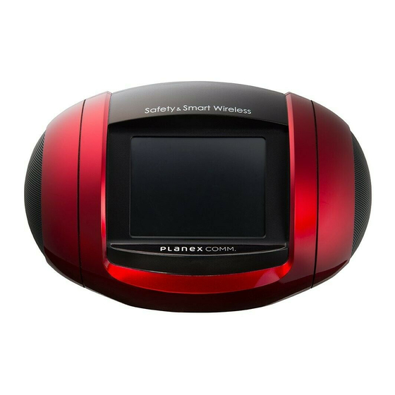
Introduction Hardware Description Power Socket USB Port Ethernet WAN RJ-45 Port Ethernet LAN PC Port RJ-45 Port Figure 1-1. Rear Panel Speaker Speaker Touch-sensitive screen Figure 1-2. Front Panel... -
Page 13: Power Socket
Hardware Description Ethernet RJ-45 Ports The Multimedia Router has the following RJ-45 ports: • The RJ-45 LAN port is for connection to a PC or to a 10/100 Mbps. • The RJ-45 WAN port is for connection to a DSL or cable modem, or to a LAN or other device that provides your Internet access. - Page 14 Introduction...
-
Page 15: Chapter 2: Installation
Chapter 2: Installation The Multimedia Router has two basic operating modes that can be set through the web-based management interface. For information on setting the mode suitable for your network environment, see “Operation Mode configuration” on page 5-4. • Gateway Mode — A gateway mode that connects a wired LAN and wireless clients to an Internet access device, such as a cable or DSL modem. -
Page 16: Bridge Mode
Installation To connect the Multimedia Router in Gateway Mode for use as an Internet gateway, follow these steps: Connect an Ethernet cable from the Multimedia Router’s WAN port to your Internet connected cable or ADSL modem. Connect an Ethernet cable from the Multimedia Router’s LAN port to your PC. Alternatively, you can connect to a workgroup switch to support multiple users. - Page 17 Bridge Mode Set up wireless Connect AC power devices adapter to power source LAN Switch Notebook PC Server Connect LAN port Connect LAN and WAN to PC ports to an Ethernet LAN Desktop PCs switch or PCs Figure 2-2. Bridge Mode Connection To connect the Multimedia Router for use as an access point, follow these steps: Connect an Ethernet cable from the Multimedia Router’s LAN and WAN ports to PCs or a LAN switch.
- Page 18 Installation...
-
Page 19: Chapter 3: Network Planning
Chapter 3: Network Planning The Multimedia Router is designed to be very flexible in its deployment options. It can be used as an Internet gateway for a small network, or as an access point to extend an existing wired network to support wireless users. It also supports use as a wireless bridge to connect two wired LANs. -
Page 20: Lan Access Point
Network Planning The private local network, connected to the LAN port or wireless interface, provides a Dynamic Host Configuration Protocol (DHCP) server for allocating IP addresses to local PCs and wireless clients, and Network Address Translation (NAT) for mapping the multiple "internal"... -
Page 21: Wireless Bridge
Wireless Bridge Wireless Bridge The IEEE 802.11 standard defines a Wireless Distribution System (WDS) for bridge connections between access points. The Multimedia Router can use WDS to forward traffic on links between units. A single WDS bridge link can be specified for the WLAN1 interface. One end of a link must be configured as the “WDS Parent”... - Page 22 Network Planning...
-
Page 23: Chapter 4: Initial Configuration
Chapter 4: Initial Configuration The Multimedia Router offers a user-friendly web-based management interface for the configuration of all the unit’s features. Any PC directly attached to the unit can access the management interface using a web browser, such as Internet Explorer (version 6.0 or above). -
Page 24: Using The Setup Wizard
Initial Configuration Using the Setup Wizard There are only a few basic steps you need to set up the Multimedia Router and provide a connection for network access for other wireless stations. The Setup Wizard takes you through configuration procedures for the general network settings. - Page 25 Using the Setup Wizard Figure 4-3. Setup Wizard - WAN DHCP • Hostname – The hostname of the DHCP client. • MAC Clone Mode – Some ISPs limit Internet connections to a specified MAC address of one PC. This setting allows you to manually change the MAC address of the Multimedia Router's WAN interface to match the PC's MAC address provided to your ISP for registration.
-
Page 26: Static Ip
Initial Configuration Static IP Configures a static IP for the WAN port. Figure 4-4. Setup Wizard - WAN Static IP • IP Address – The IP address of the Multimedia Router. Valid IP addresses consist of four decimal numbers, 0 to 255, separated by periods. •... -
Page 27: Pppoe
Using the Setup Wizard more DNS servers located on the local network, type the IP addresses in the text fields provided. Otherwise, leave the addresses as all zeros (0.0.0.0). • Secondary DNS Server – The IP address of the Secondary Domain Name Server on the network. - Page 28 Initial Configuration Figure 4-5. Setup Wizard - WAN PPPoE • PPPoE Username – Sets the PPPoE user name for the WAN port. (Default: pppoe_user; Range: 1~32 characters) • PPPoE Password – Sets a PPPoE password for the WAN port. (Default: pppoe_password; Range: 1~32 characters) •...
-
Page 29: L2Tp
Using the Setup Wizard L2TP Enables the Layer Two Tunneling Protocol (L2TP) for implementing virtual private networks. The service is provided in many European countries. Figure 4-6. Setup Wizard - WAN L2TP... -
Page 30: Pptp
Initial Configuration • Server IP – Sets the L2TP server IP Address. (Default: l2tp_server; Range: 1~32 characters) • Username – Sets the L2TP user name for the WAN port. (Default: l2tp_user; Range: 1~64 characters) • Password – Sets a L2TP password for the WAN port. (Default: l2tp_password; Range: 1~32 characters) •... - Page 31 Using the Setup Wizard Figure 4-7. Setup Wizard - PPTP • Server IP – Sets a PPTP server IP Address. (Default: pptp_server) • Username – Sets the PPTP user name for the WAN port. (Default: pptp_user; Range: 1~64 characters) • Password – Sets a PPTP password for the WAN port. (Default: pptp_password; Range: 1~32 characters)
- Page 32 Initial Configuration • Verify Password – Prompts you to re-enter your chosen password. • Address Mode – Sets a PPTP network mode. (Default: Static) • IP Address – Sets the static IP address. (Default: 0.0.0.0, available when PPTP Network Mode is set to static IP.) •...
- Page 33 Using the Setup Wizard Figure 4-8. Setup Wizard - 3G • Pin Code Protect – Enables the use of a PIN code (personal identification number) to encrypt access to the wireless 3G connection. Some service providers do not require PIN code authentication. If the PIN code for your 3G/3.5G modem is disabled, disable this function (Default: Enabled).
- Page 34 Initial Configuration By Time By Data Budget Criterion Specify the amount of time (in Specify how much Download/Upload data (in hours) that can be used per month MBytes) can be transmitted per month Budget Policy Enable or disable the action “Drop Enable or disable the action “Disallow New Current Cellular connection”...
- Page 35 Using the Setup Wizard Figure 4-9. Setup Wizard - Basic Wireless Settings 4-13...
- Page 36 Initial Configuration • Network Name (SSID) – The name of the wireless network service provided by the VAP. Clients that want to connect to the network must set their SSID to the same as that of the VAP interface. (Default: “Accton_11n_Router”; Range: 1-32 characters) •...
-
Page 37: Chapter 5: System Configuration
Chapter 5: System Configuration The Multimedia Router offers a user-friendly web-based management interface for the configuration of all the unit’s features. Any PC directly attached to the unit can access the management interface using a web browser, such as Internet Explorer (version 6.0 or above). - Page 38 System Configuration The System Information page displays the System, Internet Configuration, and Local Network Settings. Figure 5-2. System Information (Gateway Mode) The information in this chapter is organized to reflect the structure of the web management screens for easy reference. The Configuration pages include the options in the table below.
- Page 39 Table 5-1. Advanced Settings Menu Description Mode Page System Mode Operation Mode Sets the operating modes Both Network Settings Configures settings for the wide area network Gateway Sets the unit’s IP address and enables DNS Gateway 5-16 Advanced Routing Configures Static and Dynamic Routing settings Gateway 5-18 Wireless Settings...
-
Page 40: Operation Mode Configuration
System Configuration Operation Mode configuration The Operation Mode Configuration pages allow you to set up the mode suitable for your network environment. Figure 5-3. System Information (Gateway Mode) • Bridge Mode – An access point mode that extends a wired LAN to wireless clients. •... -
Page 41: Dhcp
Network Settings WAN Connection Type — By default, the access point WAN port is configured with DHCP enabled. After you have network access to the access point, you can use the web browser interface to modify the initial IP configuration, if needed. The options are Static IP, DHCP, PPPoE (ADSL), L2TP, PPTP and 3G. - Page 42 System Configuration • Hostname (Optional) – The hostname of the DHCP client. • MAC Clone Mode – Some ISPs limit Internet connections to a specified MAC address of one PC. This setting allows you to manually change the MAC address of the Multimedia Router's WAN interface to match the PC's MAC address provided to your ISP for registration.
- Page 43 Network Settings Static IP Configures a static IP for the WAN port. Figure 5-5. WAN Setting - Static IP • IP Address – The IP address of the Multimedia Router. Valid IP addresses consist of four decimal numbers, 0 to 255, separated by periods.
-
Page 44: Pppoe
System Configuration • Subnet Mask – The mask that identifies the host address bits used for routing to specific subnets. • Default Gateway – The IP address of the gateway router for the Multimedia Router, which is used if the requested destination address is not on the local subnet. •... - Page 45 Network Settings Figure 5-6. WAN Setting - PPPoE • PPPoE Username – Sets the PPPoE user name for the WAN port. (Default: pppoe_user; Range: 1~64 characters)
-
Page 46: L2Tp
System Configuration • PPPoE Password – Sets a PPPoE password for the WAN port. (Default: pppoe_password; Range: 1~32 characters) • Verify Password – Prompts you to re-enter your chosen password. • Operation Mode – Selects the operation mode as Keep Alive, On Demand or Manual. (Default: Keep Alive) - Keep Alive Mode: The Multimedia Router will periodically check your Internet connection and automatically re-establish your connection when disconnected. - Page 47 Network Settings Figure 5-7. WAN Setting - L2TP 5-11...
-
Page 48: Pptp
System Configuration • Server IP – Sets the L2TP server IP Address. (Default: l2tp_server; Range: 1~32 characters) • Username – Sets the L2TP user name for the WAN port. (Default: l2tp_user; Range: 1~64 characters) • Password – Sets a L2TP password for the WAN port. (Default: l2tp_password; Range: 1~32 characters) •... - Page 49 Network Settings Figure 5-8. WAN Setting - PPTP 5-13...
- Page 50 System Configuration • Server IP – Sets a PPTP server IP Address. (Default: pptp_server) • Username – Sets the PPTP user name for the WAN port. (Default: pptp_user; Range: 1~64 characters) • Password – Sets a PPTP password for the WAN port. (Default: pptp_password; Range: 1~32 characters) •...
- Page 51 Network Settings Figure 5-9. WAN Setting - 3G 3G – Enables a 3G/3.5G wide-area wireless cellular link on the USB port using an optional USB modem. • Start Mode: Select the 3G start mode. -Automatically: If 3G is selected as primary WAN, when you connect to the 3G modem, enter the PIN code, and then the wireless router will connect to 3G Internet service automatically.
-
Page 52: Lan Setting
System Configuration : Indicates that the 3G connection has Authenticated successfully authenticated successfully. • Dial Code: A dialled access code that connects the USB device to the service provider. • APN Service: The name that uniquely identifies the cellular operator, access point name (APN). - Page 53 Network Settings Figure 5-10. LAN Settings (Gateway Mode) • LAN IP Address – Valid IP addresses consist of four decimal numbers, 0 to 255, separated by periods. The default setting is 192.168.2.1. • Subnet Mask – Indicate the local subnet mask. (Default: 255.255.255.0.) •...
-
Page 54: Advanced Routing
System Configuration default gateway, and Domain Name Server (DNS) address are dynamically assigned to the access point by the network DHCP server. (Options: Enable/Disable) • Start/End IP Address – Specify the start and end IP addresses of a range that the DHCP server can allocate to DHCP clients. - Page 55 Network Settings Figure 5-11. Advanced Route (Gateway Mode) • Destination – A destination network or specific host to which packets can be routed. • Type – Defines the type of destination. (Options: Host/Net, Default: Host) • Gateway – The IP address of the router at the next hop to which matching frames are forwarded.
-
Page 56: Wireless Settings
System Configuration • Gateway – Displays the IP address of the router at the next hop to which matching frames are forwarded. • Flags – Possible flags identify as below - 0: reject route - 1: route is up - 3: route is up, use gateway - 5: route is up, target is a host - 7: route is up, use gateway, target is a host •... - Page 57 Wireless Settings Figure 5-13. Basic Wireless Settings • Radio On/Off – Enables or Disable the radio. (Default: Enable) • Network Mode – Defines the radio mode for the VAP interface. (Default: 802.11b/g/n Mixed) Note: Enabling the Multimedia Router to communicate with 802.11b/g clients in both 802.11b/g/n Mixed and 802.11n modes also requires that HT Operation in the Advanced Settings menu be set to Mixed.
- Page 58 System Configuration - 802.11b/g/n Mixed: All 802.11b/g/n clients can communicate with the Multimedia Router (up to 300 Mbps), but data transmission rates may be slowed to compensate for 802.11b/g clients. • Network Name (SSID) – The name of the wireless network service provided by the VAP.
- Page 59 Wireless Settings All units are configured as Gateway Mode Units can be configured as Gateway Mode and Bridge Mode combinations. (ex: 2 units for Gateway Mode and 2 units for Bridge Mode) All units are configured as Bridge Mode When both units are set to Gateway Mode, be sure to check these settings: •...
- Page 60 System Configuration capability of the VAP functioning as an AP. In this mode, traffic is not forwarded to the Ethernet port from the radio interface. In Repeater mode the Multimedia Router transmits a beacon. Note: WDS settings may only be configured for WLAN1, See “Wi-Fi Protected Setup (WPS)”...
-
Page 61: Advanced Wireless Settings
Wireless Settings Mbps and 74 Mbps respectively and ensures backward compliance for slower 802.11b devices. (Default: 20/40MHz) • Guard Interval – The guard interval between symbols helps receivers overcome the effects of multipath delays. When you add a guard time, the back portion of useful signal time is copied and appended to the front. - Page 62 System Configuration Figure 5-17. Advanced Wireless Settings • BG Protection – Enables a backward compatible protection system for 802.11b clients. There are three modes. (Default: Auto): - Auto: The Multimedia Router enables its protection mechanism for 802.11b clients when they are detected in the network. When 802.11b clients are not detected, the protection mechanism is disabled.
- Page 63 Wireless Settings default value of 2 indicates that the access point will save all broadcast/multicast frames for the Basic Service Set (BSS) and forward them after every second beacon. Using smaller DTIM intervals delivers broadcast/multicast frames in a more timely manner, causing stations in Power Save mode to wake up more often and drain power faster.
- Page 64 System Configuration Configuring Wi-Fi Multimedia Wireless networks offer an equal opportunity for all devices to transmit data from any type of application. Although this is acceptable for most applications, multimedia applications (with audio and video) are particularly sensitive to the delay and throughput variations that result from this equal opportunity wireless access method.
- Page 65 Wireless Settings Access Categories – WMM defines four access categories (ACs): voice, video, best effort, and background. These categories correspond to traffic priority levels and are mapped to IEEE 802.1D priority tags (see Table 5-1). The direct mapping of the four ACs to 802.1D priorities is specifically intended to facilitate inter operability with other wired network QoS policies.
-
Page 66: Wlan Security
System Configuration WMM Acknowledge Policy – By default, all wireless data transmissions require the sender to wait for an acknowledgement from the receiver. WMM allows the acknowledgement wait time to be turned off for each Access Category (AC). Although this increases data throughput, it can also result in a high number of errors when traffic levels are heavy. - Page 67 Wireless Settings Security The Multimedia Router supports two virtual access point (VAP) interfaces referred to as WLAN1 and WLAN2. Each VAP functions as a separate access point, and can be configured with its own security settings. Click on “Wireless Settings,” followed by “Security”. Figure 5-20.
- Page 68 System Configuration - Open: Open-system authentication accepts any client attempting to connect the Multimedia Router without verifying its identity. In this mode the default encryption type is "None". - Shared: The shared-key approach uses Wired Equivalent Privacy (WEP) to verify client identity by distributing a shared key to clients before attempting authentication.
-
Page 69: Wi-Fi Protected Setup (Wps)
Wireless Settings - WPA-PSK/WPA2-PSK: The WPA or WPA2 mode uses a common password phrase, called a Pre-Shared Key, that must be manually distributed to all clients that want to connect to the network. Specify a key as an easy-to-remember form of letters and numbers. - Page 70 System Configuration Figure 5-21. WPS Settings WPS Function — Enables WPS, locks security settings, and refreshes WPS configuration information. • WPS – Enables WPS. (Default: Disable) WPS Summary – Provides detailed WPS statistical information. • WPS Current Status – Displays if there is currently any WPS traffic connecting to the Multimedia Router.
-
Page 71: Station List
Firewall Figure 5-22. WPS Progress Settings WPS Configuration — Configures WPS settings for the Multimedia Router. • WPS Mode – Selects between methods of broadcasting the WPS beacon to network clients wanting to join the network: - PIN: The Multimedia Router, along with other WPS devices, such as notebook PCs, cameras, or phones, all come with their own eight-digit PIN code. -
Page 72: Mac/Ip/Port Filtering
System Configuration MAC/IP/Port Filtering MAC/IP/Port filtering restricts connection parameters to limit the risk of intrusion and defends against a wide array of common hacker attacks. IP/Port filtering allows the unit to permit, deny or proxy traffic through its MAC addresses, IP addresses and ports. The Multimedia Router allows you define a sequential list of permit or deny filtering rules (up to 32). -
Page 73: Virtual Server Settings (Port Forwarding)
Firewall • Destination IP Address – Specifies the destination IP address to block or allow traffic from. • Source IP Address – Specifies the source IP address to block or allow traffic from. • Protocol – Specifies the destination port type, TCP, UDP or ICMP. (Default: None). •... - Page 74 System Configuration Figure 5-26. Virtual Server Settings (Port Forwarding) • Virtual Server Setting – Selects between enabling or disabling port forwarding the virtual server. (Default: Disable) • IP Address – Specifies the IP address on the local network to allow external access to. •...
-
Page 75: System Security
Firewall Enables a specified host PC on the local network to access the Internet without any firewall protection. Some Internet applications, such as interactive games or video conferencing, may not function properly behind the Multimedia Router's firewall. By specifying a Demilitarized Zone (DMZ) host, the PC's TCP ports are completely exposed to the Internet, allowing open two-way communication. -
Page 76: Content Filtering
System Configuration Figure 5-28. System Security Settings • Remote Management – Denies or allows a remote access via WAN. (Default: Deny) • Ping from WAN Filter – Sends a ping request on the WAN port to test for connectivity. (Default: Disable) •... - Page 77 Firewall Figure 5-29. Filter Settings Webs Content Filter Settings — The Multimedia Router blocks access to specific traffic such as proxies, Java Applets and ActiveX. Check the box for whichever service to be blocked then click “Apply”. • Filter – Selects Webs content filters. (Options: Proxy/Java/ActivX) Current Web URLs Filters —...
-
Page 78: Administration Settings
System Configuration Current Website Host Filters — The Multimedia Router allows Internet content access to be restricted based on web address keywords and web domains. A domain name is the name of a particular web site. For example, for the address www.FUNGAMES.com, the domain name is FUNGAMES.com. - Page 79 Administration Settings Administrator Settings To protect access to the management interface, you need to configure a new Administrator’s user name and password as soon as possible. If a new user name and password are not configured, then anyone having access to the Multimedia Router may be able to compromise the unit's security by entering the default values.
-
Page 80: Upgrade Firmware
System Configuration Figure 5-32. Green AP Settings DDNS Settings Dynamic DNS (DDNS) provides users on the Internet with a method to tie a specific domain name to the unit’s dynamically assigned IP address. DDNS allows your domain name to follow your IP address automatically by changing your DNS records when your IP address changes. -
Page 81: Configuration Settings
Administration Settings Figure 5-34. Upgrade Firmware Update Firmware — Allows you to upload new firmware manually by specifying a file path. Make sure the firmware you want to use is on the local computer by clicking Browse to search for the firmware to be used for the update. •... -
Page 82: System Status
System Configuration Figure 5-35. Configuration Settings • Load Factory Defaults – Restores the factory defaults. • Export – Saves the current configuration to a file locally. • Import – Allows the user to load previously saved configuration files from a local source. System Status The System Information page displays basic system information and the displayed settings are for status information only and are not configurable on this page. - Page 83 Administration Settings System Info — Displays the basic system information in both Bridge and Gateway Modes: • Software Version – The version number of the current Multimedia Router software. • Hardware Version – The version number of the current Multimedia Router hardware. •...
-
Page 84: Statistics
System Configuration • Local Netmask – The mask that identifies the host address bits used for routing to the LAN port. • MAC Address – The shared physical layer address for the Multimedia Router’s LAN port. Statistics The Multimedia Router Traffic Statistics - Interfaces window displays received and transmitted packet statistics for all interfaces on the Multimedia Router. -
Page 85: Dhcp Clients
Administration Settings DHCP Clients Lists information about associated DHCP clients. Figure 5-40. DHCP Client List (Gateway Mode) • MAC Address – The MAC address of the DHCP client. • IP Address – The IP address of the DHCP client. • Expires in – The time after which the connection will expire and the DHCP client must request a new IP address. -
Page 86: Reboot
System Configuration Reboot • Reboot – Click the button to reboot the Multimedia Router. Figure 5-42. System Reboot 5-50... -
Page 87: Chapter 6: Using The On-Screen Display Menus
Chapter 6: Using the On-Screen Display menus The Multimedia Router is equipped with a set of user-friendly On-Screen Display (OSD) menus which provide various functions when your are connected to the Internet or disconnected. Using the menus When the Multimedia Router is powered on, you will hear a ring tone and the main menu appears on the screen. -
Page 88: Updating The Firmware
Using the On-Screen Display menus Updating the Firmware Upon connecting the Multimedia Router to the Internet, the unit will check automatically if any updated firmware is ready for installation. Follow the steps below to complete firmware update. Note: Before updating firmware, make sure at least 128MB of free space is available in the Multimedia Router’s internal memory. -
Page 89: The Internet Menu
The Internet menu The Internet menu Note: Before using this menu, make sure the Multimedia Router is connected to the Internet. to open the Internet menu, and you can select to access Internet radio, video clips or photo albums. • Internet Radio to enter the Internet Radio screen. - Page 90 Using the On-Screen Display menus To input the keyword for your desired video clips, tap anywhere inside the Search: box to enter the Keypad screen. Text input box Enter the keyword in the text input box. When finished, tap to go back to the YouTube setting screen.
-
Page 91: The Media Center Menu
The Media Center menu • FrameChannel Note: To use FrameChannel, you will need to register a FrameChannel account on the Internet first and then upload photos to your FrameChannel Web Album. Go to www.framechannel.com. for details on how to manage your account. to enter the FrameChannel setting screen. - Page 92 Using the On-Screen Display menus When finished, tap to disconnect the Multimedia Router from your computer. • FM Radio Favorite station list to enter the FM radio screen. The preset FM radio station starts broadcasting automatically. You can save up to 5 most-listened-to radio stations by adding them to your favorite station list.
- Page 93 The Media Center menu Tap anywhere on the screen to display the tool bar. To view the photos in slideshow, . Playback of music also starts if one or more music files are stored in the internal memory. - To pause/resume the music, tap - To switch back to single photo view, tap - To go to the previous/next photo, tap - To adjust the volume, tap...
-
Page 94: The Calendar Menu
Using the On-Screen Display menus - To pause/resume playback, tap - To go to the previous/next photo, tap - To adjust the volume, tap . To mute the sound, tap • Video To view video clips, you need to copy video files to the Router first. For details, see “To copy files to the Multimedia Router:”... - Page 95 The Calendar menu • Clock to view the current time. To adjust the time, tap to open the time setting page. Tap to adjust it to your local time, and tap to confirm the settings. • Calendar to view the current date. To adjust the date, tap anywhere on the calendar to open the date setting page.
-
Page 96: The Tools Menu
Using the On-Screen Display menus • Alarm to view the current alarm settings. To adjust the settings, tap to open the alarm setting page. You can set the alarm time by tapping , and tap the day(s) you need the alarm through Sunday to Saturday. When finished, tap activate the alarm, and tap to confirm the settings. - Page 97 The Tools menu Table 6-1. Setup Menu name • Description Default To return all the settings to the factory preset values, tap Default Setting Setting Execute and then to reset all settings. Format To erase all data stored in the internal memory, tap Format Format then...
- Page 98 Using the On-Screen Display menus - 3G 3G setting : Tap if you use 3G as the Internet connection method. The 3G connection setting info appears. Fill in the info using the on-screen keypad. When done, tap Note: To use this option, you need to first connect a 3G/3.5G USB modem to the USB port on the back of the unit and have registered an account with a cellular operator.
- Page 99 The Tools menu keypad. When done, tap Note: To use this option, you need to first connect your multimedia router to an Internet connected cable or ADSL modem, and wired or wireless PCs or notebooks. See “Installation” on page 2-1 for detailed installation. For more details on the WAN settings, see “WAN Setting”...
- Page 100 Using the On-Screen Display menus When the green light is on, it indicates that the LAN/WAN connection is successful. Note: If you wish to use this function, your LAN IP address must be set to “192.168.1.1” (default). • System Information To view the system information, tap System Information.
-
Page 101: Appendix A: Troubleshooting
Appendix A: Troubleshooting Check the following items before you contact local Technical Support. If wireless clients cannot access the network, check the following: • Be sure the access point and the wireless clients are configured with the same Service Set ID (SSID). •... - Page 102 Troubleshooting...
-
Page 103: Appendix B: Specifications
Appendix B: Specifications Operating Frequency 802.11b/g/n: 2.412 ~ 2.462 GHz (USA, Canada Ch1- Ch11) 2.412 ~ 2.472 GHz (Europe Ch1- Ch13) 2.412 ~ 2.484 GHz (Japan Ch1- Ch13) 2.412 ~ 2.462 GHz (Taiwan Ch1-Ch11) Data Rate 802.11b: 1, 2, 5.5, 11 Mbps per channel 802.11g: 6, 9, 12, 18, 24, 36, 48, 54 Mbps per channel 802.11n: MCS 0~7 Operating Channels... - Page 104 Specifications Radio Signal Certification FCC Part 15C 15.247, 15.207 (2.4 GHz) EN 300 328 EN 301 489-1 EN 301 489-17 Standards IEEE 802.11b/g IEEE 802.11n draft v2.0 Physical Size 193 x 119 x 130 mm (7.60 x 4.69 x 5.12 in) Weight <...
-
Page 105: Glossary
Glossary 10BASE-T IEEE 802.3-2005 specification for 10 Mbps Ethernet over two pairs of Category 3 or better UTP cable. 100BASE-TX IEEE 802.3-2005 specification for 100 Mbps Fast Ethernet over two pairs of Category 5 or better UTP cable. Access Point An internetworking device that seamlessly connects wired and wireless networks. - Page 106 Glossary Encryption Data passing between the access point and clients can use encryption to protect from interception and evesdropping. Ethernet A popular local area data communications network, which accepts transmission from computers and terminals. File Transfer Protocol (FTP) A TCP/IP protocol used for file transfer. Hypertext Transfer Protocol (HTTP) HTTP is a standard used to transmit and receive all data over the World Wide Web.
- Page 107 Glossary Open System A security option which broadcasts a beacon signal including the access point’s configured SSID. Wireless clients can read the SSID from the beacon, and automatically reset their SSID to allow immediate connection to the nearest access point. Orthogonal Frequency Division Multiplexing (ODFM) OFDM allows multiple users to transmit in an allocated band by dividing the bandwidth into many narrow bandwidth carriers.
- Page 108 Glossary within the device’s footprint can associate with what appears to be different access points and their associated network services. All the services are delivered using a single radio channel, enabling Virtual AP technology to optimize the use of limited WLAN radio spectrum.
-
Page 109: Index
Index AC power adapter LAN setting 5-16 administrator password 5-43 administrator username 5-43 Advanced Setting menu 5-25 MDI/MDI-X, automatic AP mode authentication mode 5-31 NTP server 5-43 bridge 3-3, 5-23 package checklist power socket channels, maximum PPPoE 4-8, 4-9, 5-12, 5-14 clients, maximum contents, package reboot... - Page 110 Index-2...
- Page 112 MZK-WDPR MZK-WDPR Multimedia Router...
Need help?
Do you have a question about the MZK-WDPR and is the answer not in the manual?
Questions and answers