Table of Contents
Advertisement
visible
user
leading
healthy
clean air
economical
flame
friendly
design
home
approved
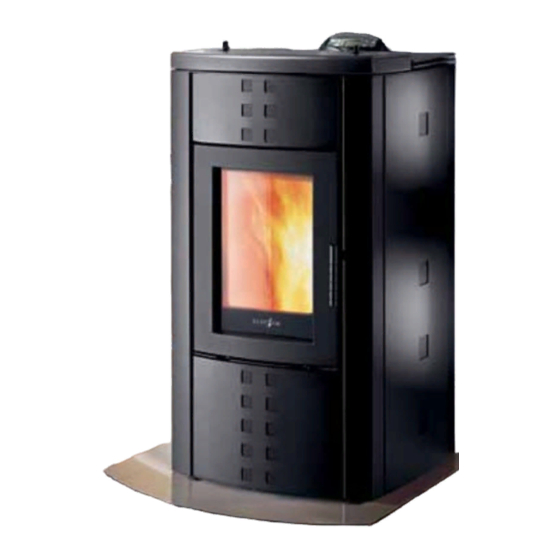
Amalfi Wood Pellet Burning Heater
Owner's & Installation Manual
PLEASE READ THIS ENTIRE MANUAL BEFORE INSTALLATION AND USE OF THIS PELLET BURNING ROOM
HEATER. FAILURE TO FOLLOW THESE INSTRUCTIONS COULD RESULT IN PROPERTY DAMAGE, BODILY
INJURY, OR EVEN DEATH.
Contact your local building or fire official about restrictions and installation inspection requirements in your area.
Advertisement
Chapters
Table of Contents

Related Manuals for Ecotec Amalfi

Summary of Contents for Ecotec Amalfi
- Page 1 Amalfi Wood Pellet Burning Heater Owner’s & Installation Manual PLEASE READ THIS ENTIRE MANUAL BEFORE INSTALLATION AND USE OF THIS PELLET BURNING ROOM HEATER. FAILURE TO FOLLOW THESE INSTRUCTIONS COULD RESULT IN PROPERTY DAMAGE, BODILY INJURY, OR EVEN DEATH.
-
Page 2: Table Of Contents
Owner’s Section Table of Contents Introduction ..................4 Specifications ....................4 1.1.1 Rating label Location ..................4 1.1.2 Specifications ....................4 1.1.3 Floor Protection .................... 4 Measurements ....................5 Safety Warnings & Recommendations ......... 6 Deciding where to locate your wood pellet burning heater ......6 Ash ........................ - Page 3 Cleaning the surfaces ..................18 Cleaning the fire pot before and after each lighting ........18 Description of Inner parts of the Ecoteck Amalfi ......... 19 Routine Cleaning (every two - three days) ........... 19 Cleaning the glass ..................21 Cleaning the Flue ...................
-
Page 4: Introduction
Due to the operating nature of the Amalfi pellet heater where opening the door causes a loss of vacuum and the fire will shut down completely, meaning the likelihood of any hot embers or burning fuel escaping from the combustion... -
Page 5: Measurements
Measurements Figure 1. -
Page 6: Safety Warnings & Recommendations
Safety Warnings & Recommendations Pellet quality is important, please read the following: Your pellet heater has been designed to burn ¼” (6mm) diameter wood pellets, manufactured to the AS/NZS 4014.6 only. DO NOT use this appliance as an incinerator. DO NOT use unsuitable and non recommended fuels, including liquid fuels as this will void any warranties stated in the manual. -
Page 7: Flammable Liquids
Do not clean the heater until the structure and the ashes have cooled down completely. Carry out all operations in maximum safety. Amalfi requires a power source to function. This is standard mains feed 240v plug - if this is unavailable in close proximity a grounded extension lead may be used. -
Page 8: Safety Devices
the switching off phase, guaranteeing safe functioning. The burn pot used for combustion allows most of the ashes produced by the combustion of the pellets to fall into the collection drawer. However, it is recommended that you check the burn pot every day, as not all pellets have high standards of quality and could leave residue that is difficult to remove. -
Page 9: Operating Your Pellet Fire
Operating your Pellet Fire Description of the Controls P1 : Turns heat level down P2 : Turns heat level up 20°C P3 : Turns fiire on-off 10:00 20°C P4 : Turns thermostat down P5 : Turns thermostat up P6 : Decrease water temperature P7 : Increase water temperature Figure 2. -
Page 10: Priming Of The Screw (Auger)
Priming of the Screw (Auger) To prime the screw/auger (when the stove is new or has been completely run out of fuel, the loading screw/auger is empty), proceed as follows: Turn the stove off completely, using the general switch on the back The display will show FINAL CLEANING and then OFF. -
Page 11: Setting The Clock (Clock Set Menu)
Setting the Clock (Clock Set Menu) Proceed as follows to set the current time: Switch the power supply to the thermostove on and off using the main switch at the back of the stove. The display will display FINAL CLEANING and then OFF. Keep key P4 pressed for 2 seconds. -
Page 12: Description Of The Strings
The strings that appear on the display go from UT05 to PR40. A setting from a program corresponds to each string. Strings Description Values that can be set UT05 START PROGRAM 1 From 00:00 to 23:50 at steps of 10’ UT06 STOP PROGRAM 1 From 00:00 to 23.50 at steps of 10’... - Page 13 Example Display this screen as described in chapter 3.7. Set the time you want PROGRAM 1 to come on UT05 with keys P4 and P5. Press key P6 to confirm 06:00 START and go on to string UT07. ( if you make a mistake, PROGRAM 1 press key P7 to go back one step) Figure 7.
-
Page 14: Setting The Language (Language Menu)
Setting the Language (Language Menu) To set the language, proceed as follows: Remove and reset the electricity supply of the stove using the general switch on the back. The display will show FINAL CLEANING and then OFF. Keep button P4 pressed for 2 seconds, CLOCK SETTING MENU will appear. Press button P4 twice;... -
Page 15: Modification Of The Boiler Water Temperature Setting
EXTERNAL THERMOSTAT PROCEDURE If an external thermostat is used, correctly connected to the mother board as shown in the electrical circuit diagram, the message T ON will be shown on the display instead of room temperature. Room temperature will be adjusted directly by the thermostat mounted on the wall. When the temperature shown on the display is reached, the message WORK MODULATION will appear on the screen. -
Page 16: 3.15.2 Symbols
3.15.2 Symbols SYMBOL DESCRIPTION SYMBOL DESCRIPTION Chronothermostat On Winter Setting On (Always) Three-Way Valve Positioned Resistance On On Radiators Water Temperature Lower Than Water Pressure Anomaly Set Temperature Pump On 3.16 Description of Alarms WARNING REASON SOLUTION • Fault in the sensor recording flue temperature SMOKE PROBE ALARM •... -
Page 17: Amalfi Electrical Circuit Diagram
3.17 Amalfi Electrical Circuit Diagram Brown Blue Yellow / Green Blue Brown Figure 13. -
Page 18: Maintenance And Cleaning
Maintenance and Cleaning Before carrying out any maintenance take the following precautions: • Make sure that the fire has been turned off, and that the general power supply has been disconnected (Ensure that the plug is disconnected from the socket, thus avoiding accidental electric shocks). •... -
Page 19: Description Of Inner Parts Of The Ecoteck Amalfi
Description of Inner parts of the Ecoteck Amalfi Fire pot Fire pot holder Ash drawer Ash drawer compartment Drawer cover guard Fire pot cover grill Figure 15. Figure 16. Routine Cleaning (every two - three days) Remove the fire pot to check how clean it is Remove the fire pot cover grill so that the and to be able to reach the fire pot holder. - Page 20 Vacuum the ash deposited in the compartment Unscrew the side ceramic brick to reach the under the drawer with a vacuum cleaner. smoke duct cleaning plates. Unscrew and vacuum the deposited ash. Before carrying out the operation described above, clean the tube bundle with the cleaning rods, as shown in the following figure.
-
Page 21: Cleaning The Glass
Cleaning the glass The glass is self-cleaning, therefore while the stove is in operation, a flow of air runs along the surface of the glass keeping ash and dirt away. However, a greyish patina will form after a few hours and this must be cleaned once the stove has been turned off. -
Page 22: Guarantee
Guarantee Certificate of Guarantee Ecoteck thanks you for the confidence you have placed in it with the purchase of one of our pellet stoves and invites the purchaser to: - examine the instructions for the installation, use and maintenance of the stove. - examine the conditions of guarantee shown below. -
Page 23: What Are Wood Pellets
What are Wood Pellets? Wood pellets are made from sawdust and wood shavings. The material used cannot contain any foreign substance such as glue, varnish or synthetic substances. Subjecting it to high pressure, the wood is pressed through a plate with holes and due to the high pressure the sawdust is heated activating the natural binders of the wood. - Page 24 Installation Section Table of Contents Dimensions (Ecoteck Amalfi) Deciding where to locate your wood pellet burning heater: Clearances to Combustibles – Ecoteck Amalfi Freestanding Exhaust and Fresh Air Intake Locations Safety devices for closed expansion tank system 27 Installation Dimensions – Amalfi Freestanding Clearances &...
-
Page 25: Dimensions (Ecoteck Amalfi)
Dimensions (Ecoteck Amalfi) Unit of Measurement Height 1079 Width Depth Weight Diameter of smoke exhaust duct Min.-max. calorific power Kw/h 3.4 - 8.4 Min.-max. hourly consump- Kg/h 0.8 - 2 tion of pellets Electrical power absorbed 550 MAX during operation... -
Page 26: Deciding Where To Locate Your Wood Pellet Burning Heater
Due to the operating nature of the Amalfi pellet heater where opening the door causes a loss of vacuum and the fire will shut down completely, meaning the likelihood of any hot embers or burning fuel escaping from the combustion chamber is extremely minimal. -
Page 27: Exhaust And Fresh Air Intake Locations
1.5 bars. Installation recommendations Warning: Our thermal stoves are fitted with 3-litre (Genova, Pisa) and 6-litre (Venezia, Amalfi ) expansion tanks. For thermal stoves with a 3-litre expansion tank a further expansion tank with a capacity of at least 15 litres must be installed in the circuit. - Page 28 After positioning the thermal stove and installing all the smoke discharge pipes, the hydraulic plant can be connected. First of all make sure that the bleeder valve ( 1 ), on the top right-hand side of the boiler (see images below) is closed when the water is filling as shown in the figure below. FILLING MUST BE CARRIED OUT VIA THE “T”...
-
Page 29: Installation
Installation Dimensions – Amalfi Freestanding 1079 1046 Figure 23. Refer to Safety Test 09/1910 for all clearances to combustible. Clearances & Specifications Minimum clearances shown are in millimetres. All Ecoteck fires are tested to AS/NZS2918:2001. Specifications were correct at time of printing but may alter and those detailed below should be used as a guide only. -
Page 30: Minimum Clearance To Combustibles
Positioning the fire: Generally Amalfi should be installed in a centrally located position within the home. When deciding where to position the appliance in your room you need to consider the following: •... -
Page 31: Internal Standard Flue Kit (50)
2.6.1 Flue Pellet Fire Flue Kits The thermostove functions irrespective of the flue’s draught since it is the smoke engine that conveys the smoke from the combustion chamber to the flue. External Standard Flue Kit Installation Examples Internal Standard Flue Kit (50) This flue kit may be used in new and replacement This ue kit may be used in new and replacement applications in rooms with stud height of 2.4m. -
Page 32: External Standard Flue Kit (51)
Pellet Fire Flue Kits External Standard Flue Kit (51) Internal Standard Flue Kit This flue kit may be used in new and replacement applications with the flue penetrating the wall This ue kit may be used in new and replacement behind the fire, running vertically up an outside applications in rooms with stud height of 2.4m. -
Page 33: Hydraulic Installation
Hydraulic Installation 2.9.1 Open vase plant safety devices According to standard UNI 10412-2 (2006) in force in Italy, systems with open expansion vases must be fitted with: • Open expansion vase • Safety pipe • Loading pipe • Circulator control thermostat (except for natural circulation systems) •... - Page 34 First of all check that the relief valve ( 1 ), situated on the upper right hand side of the boiler (see Figure 24 and Figure 25) is open once the water has been filled as shown in the figure below. Figure 24.
-
Page 35: Seismic Restraint
This diagram is given as an indication only. Installation must be carried out by a plumber. Figure 27. 2.10 Seismic Restraint All installation scenarios for Amalfi require the use of hold-down anchors (one on each side). Fixing to Concrete Floor: • Minimum M8 expansion anchors (M10 recommended) or min M8 epoxy- set anchors. -
Page 36: How To Remove The Side Panels
2.12 How to remove the side panels SLACKEN THE THREE SCREWS TO DISMANTLE THE PELLET DOOR. Figure 28. REMOVE THE SCREWS ON THE TOP PLATE TO DISMANTLE THE SIDES. Figure 29. REMOVE THE SIDE PANELS. Figure 30. -
Page 37: Seismic Restraint Locations
2.13 Seismic Restraint Locations SEISMIC RESTRAINT LOCATION SEISMIC RESTRAINT LOCATION Figure 31. -
Page 38: Installation Data Sheet
Installation Data Sheet Name of Owner: Name of Dealer: ________________________________ ________________________________ Address: Address: ________________________________ ________________________________ ________________________________ ________________________________ ________________________________ ________________________________ ________________________________ ________________________________ Phone: Phone: ________________________________ ________________________________ Model: __________________________ Name of Installer: ________________________________ Serial Number: ____________________ Address: Date of Purchase: __________ (dd/mm/yy) ________________________________ Date of Installation: _________ ________________________________... -
Page 39: Maintenance Record
Maintenance Record DATE WORK CARRIED OUT SIGNATURE...
Need help?
Do you have a question about the Amalfi and is the answer not in the manual?
Questions and answers