Table of Contents
Advertisement
Quick Links
Tomcat i7221 S5150
User's Manual
///
Tomcat i7221
S5150
Revision 1.01
Copyright © TYAN Computer Corporation, 2004. All rights reserved. No part of this manual
may be reproduced or translated without prior written consent from TYAN Computer Corp.
All registered and unregistered trademarks and company names contained in this manual are
property of their respective owners including, but not limited to the following.
TYAN, Tomcat, i7221 and S5150 are trademarks of TYAN Computer Corporation.
Intel Prescott and combinations thereof are trademarks of Intel Corporation.
Promise is a trademark of Promise Technology, Inc.
Award, AwardBIOS are trademarks of Award Software Incorporated.
Microsoft and Windows are trademarks of Microsoft Corporation.
IBM, PC, AT and PS/2 are trademarks of IBM Corporation.
Winbond is a trademark of Winbond Electronics Corporation.
SMSC is a trademark of Standard Microsystems Corporation.
Broadcom is a trademark of Broadcom Corporation.
Portable Document Format (PDF) is a trademark of Adobe Corporation.
Information contained in this document is furnished by TYAN Computer Corporation and has
been reviewed for accuracy and reliability prior to printing.
TYAN assumes no liability
whatsoever, and disclaims any express or implied warranty, relating to sale and/or use of
TYAN products including liability or warranties relating to fitness for a particular purpose or
merchantability.
TYAN retains the right to make changes to product descriptions and/or
specifications at any time, without notice. In no event will TYAN be held liable for any direct or
indirect, incidental or consequential damage, loss of use, loss of data or other malady resulting
from errors or inaccuracies of information contained in this document.
i
http://www.tyan.com
Advertisement
Table of Contents

Subscribe to Our Youtube Channel
Related Manuals for TYAN Tomcat i7221 S5150


Summary of Contents for TYAN Tomcat i7221 S5150
- Page 1 TYAN retains the right to make changes to product descriptions and/or specifications at any time, without notice. In no event will TYAN be held liable for any direct or indirect, incidental or consequential damage, loss of use, loss of data or other malady resulting from errors or inaccuracies of information contained in this document.
-
Page 2: Table Of Contents
Tomcat i7221 S5150 Table of Contents Table of Contents Before you begin… ........................v Chapter 1: Introduction......................1 1.1 Congratulations!......................1 1.2 Hardware Specifications ....................1 Chapter 2: Board Installation ....................1 2.1 Installing the Motherboard .................... 1 2.1.1 Installation Notes ....................1 2.2 Board Image ......................... - Page 3 Tomcat i7221 S5150 Table of Contents 3.5.1 PCI Express Root Port Function............... 14 3.6 Integrated Peripherals....................16 3.6.1 OnChip IDE Device................... 16 3.6.2 Onboard Device....................18 3.6.3 Super IO Device....................19 3.7 Power Management Setup ..................21 3.7.1 PCI Express PM Function................. 23 3.7.2 Power On Setup....................
- Page 4 Tomcat i7221 S5150 Table of Contents 4.10.2 Windows* 2003 / Windows 2000 ..............22 4.11 Unattended Installation Under Windows* 2003 / Windows 2000......23 4.12 Intel Storage Utility ....................23 4.12.1 Description ...................... 23 4.12.2 Create Volume Manually ................24 4.12.3 Successful Creation ..................
-
Page 5: Before You Begin
1 x 34-Pin floppy drive cable 1 x Ultra-DMA-133/100/66/33 IDE cable 1 x Tomcat i7221 S5150 User’s Manual 1 x Tomcat i7221 S5150 Quick Reference Guide 1 x TYAN driver CD 1 x Intel 82801FR (ICH6R) Driver Diskette 1 x Adaptec Driver Diskette... -
Page 6: Chapter 1: Introduction
With the x1 PCI Express slots, onboard two Gigabit Ethernet port, Serial ATA RAID, four Dual-channel DDR DIMM sockets, plus the optional SCSI, four port and eight port Serial ATA modules, the Tomcat i7221 S5150 is fast and flexible enough to fit your server/workstation needs. - Page 7 Stacked two USB2.0 ports One 15-pin VGA port One 9-pin COM port Six audio jacks (optional) Two RJ45 10/100/1000 Base-T port w/ activity LED Note TYAN reserves the right to add support or discontinue support for any OS with or without notice. http://www.tyan.com...
-
Page 8: Chapter 2: Board Installation
Chapter 2: Board Installation 2.1 Installing the Motherboard The Tomcat i7221 S5150 motherboard conforms fully to the ATX specification. Before continuing with the installation, confirm that your chassis supports a standard ATX motherboard. If you are unsure, contact your dealer for more information. -
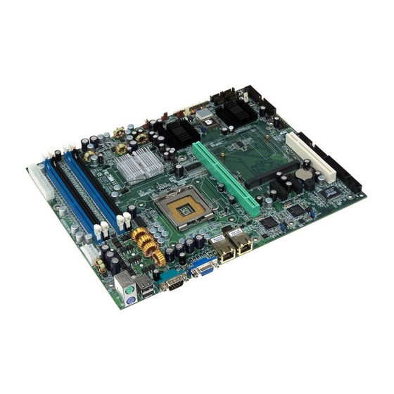
Page 9: Board Image
Chapter 2: Board Installation 2.2 Board Image The following is an image of the Tomcat i7221 S5150. The above photograph is purely representative. Due to engineering updates and new board revisions, certain components may change and or be repositioned. The picture above may or may not look exactly like the board you received. -
Page 10: Block Diagram
Tomcat i7221 S5150 Chapter 2: Board Installation 2.3 Block Diagram The following is a block diagram of the Tomcat i7221 S5150. PRESCOTT CLOCK LGA775 CHIP 800 MHz SYSTEM BUS DDR 333/400 DDR A DIMMS MD/MA PCI-X CONNECTOR 133MHz OR 100MHz PCI-X... -
Page 11: Motherboard Components
Tomcat i7221 S5150 Chapter 2: Board Installation 2.4 Motherboard Components The diagram below shows the main motherboard components. P1FAN KB(Bottom) KB / MS Mouse(Top) DIM M4 DIMM3 USB1 DIMM2 DIMM1 (COM1) S5150 (VGA) Intel E7221 LAN1 LAN2 FAN6 JP17 Intel... -
Page 12: Jumpers And Connectors
Tomcat i7221 S5150 Chapter 2: Board Installation 2.5 Jumpers and Connectors Jumpers and pin headers are provided on your motherboard for configuration and connection to peripherals. The following section shows you how to set your jumpers and use your pin headers. -
Page 13: Serial Port: Com2 (J5)
Tomcat i7221 S5150 Chapter 2: Board Installation 2.5.1 Serial Port: COM2 (J5) P1FAN K B(B ottom) K B / MS Mouse(Top) DIMM4 J P4 DIMM3 USB1 DIM M2 DIM M1 ( CO M 1) S5150 (VGA) I ntel E72 21... -
Page 14: Serial Ata Raid Connectors: J19/J20/J21/J22 (Sata1 / Sata3 / Sata2 / Sata4)
Tomcat i7221 S5150 Chapter 2: Board Installation 2.5.3 Serial ATA RAID Connectors: J19/J20/J21/J22 (SATA1 / SATA3 / SATA2 / SATA4) P1FAN K B(B ottom) KB / MS Mouse(Top) DIMM4 DIMM3 J P4 USB1 DIM M2 DIM M1 ( CO M 1) -
Page 15: Front Panel Lan1/Lan2 Link And Active Led Connector: Jp3/Jp6
Tomcat i7221 S5150 Chapter 2: Board Installation 2.5.5 Front Panel LAN1/LAN2 Link and Active LED Connector: JP3/JP6 P1FAN K B(B ottom) KB / MS Pin 1: LED+ Mouse(Top) DIMM4 J P4 DIMM3 USB1 Pin 2: LED- DIM M2 DIM M1... -
Page 16: Front Panel Lan1/Lan2 Speed Led Pin-Header: Jp5/Jp7
Tomcat i7221 S5150 Chapter 2: Board Installation 2.5.7 Front Panel LAN1/LAN2 Speed LED Pin-Header: JP5/JP7 P1FAN K B(B ottom) KB / MS Pin 2: Green+ Mouse(Top) DIMM4 J P4 DIMM3 USB1 Pin 1: Orange+ DIM M2 DIM M1 ( CO M 1) -
Page 17: Front Panel Usb 2.0 Connector: Jp11/Jp12
Tomcat i7221 S5150 Chapter 2: Board Installation 2.5.9 Front Panel USB 2.0 Connector: JP11/JP12 P1FAN PW 2 K B(B ottom) K B / MS Mouse(Top) DIMM4 J P4 DIMM3 USB1 DIM M2 DIM M1 ( CO M 1) S5150 (VGA) -
Page 18: Front Panel System Connector: Jp14
Tomcat i7221 S5150 Chapter 2: Board Installation 2.5.11 Front Panel System Connector: JP14 Your chassis will usually come with connectors to install onto the motherboard, such as HD and Power LEDs. The Front Panel Connector (JP14) has been implemented for such purposes. -
Page 19: Chassis Fan Connector: Jp16 (Fan1)
JP11 JP12 F DD J1 3 LPT J8 JP10 2.5.14 SMDC Connector: JP19 (Optional) P1FAN K B(B ottom) K B / MS For connection with Tyan Server Mouse(Top) DIMM4 DIMM3 J P4 USB1 Management Daughter Card (SMDC) DIM M2 DIM M1... -
Page 20: Pci-X Speed Select Header: Jp20
Tomcat i7221 S5150 Chapter 2: Board Installation 2.5.15 PCI-X Speed Select Header: JP20 P1FAN K B(B ottom) K B / MS Mouse(Top) DIMM4 DIMM3 J P4 USB1 DIM M2 DIM M1 ( CO M 1) Pin 1-2 Closed: 133MHz S5150... -
Page 21: Mounting The Motherboard
Some chassis’ include plastic studs instead of metal. Although the plastic studs are usable, TYAN recommends using metal studs with screws that will fasten the motherboard more securely in place. See the diagram below for some examples of typical motherboard fixing studs. -
Page 22: Installing Memory
• All installed memory will be automatically detected and no jumpers or settings need to be set. • The Tomcat i7221 S5150 supports up to 4GB of memory • Registered Memory is NOT supported. • You can install either single or double-sided modules on this motherboard. Each DIMM can work in single-channel mode or dual-channel mode. -
Page 23: Memory Installation Procedure
Seat the module firmly into the socket by gently pressing down until it sits flush with the socket. The locking levers pop up into place. 2.8 Installing the Processor and Cooling Fan Your Tomcat i7221 S5150 supports the latest processor technologies from Intel. Check the TYAN website for latest processor support: http://www.tyan.com Processor Installation The processor should be installed carefully. - Page 24 Tomcat i7221 S5150 Chapter 2: Board Installation Locate the processor socket on the motherboard and lift the protective cover off as shown. WARNING This new processor socket designed by Intel is easily damaged. The processor has to be installed very carefully to prevent the contact pins of the socket from breaking.
- Page 25 Tomcat i7221 S5150 Chapter 2: Board Installation Follow these instructions to install the heatsink shown. Apply some thermal compound (also called heatsink compound or thermal grease) to the top of the processor. Try and apply a thin, even layer over the top of the processor.
-
Page 26: Installing Drive Cables
2.9 Installing Drive Cables IDE and FDD connectors are “keyed” to only allow insertion only one way. TYAN motherboards have two on-board IDE channels, each supporting two drives. The black connector is the Primary IDE connector. -
Page 27: Installing Expansion Cards
Tomcat i7221 S5150 Chapter 2: Board Installation Troubleshooting Floppy Drives See the chart below for troubleshooting floppy disk drive installations. Symptoms of incorrectly installed floppy drives Usually caused by faulty cables, cables put in backwards or a faulty floppy drive. Try another floppy drive or try replacing the cable. -
Page 28: Connecting External Devices
Tomcat i7221 S5150 Chapter 2: Board Installation 2.11 Connecting External Devices Your new motherboard supports a number of different interfaces for connecting peripherals. See the diagram below. Some I/O ports may not be available with the board due to the different configurations. -
Page 29: Installing The Power Supply
If you experience difficulty, you can find help by asking your vendor for assistance. If they are not available for assistance, please find setup information and documentation online at our website (www.tyan.com) or by calling your vendor’s support line. 2-22... -
Page 30: Chapter 3: Bios Setup
Tomcat i7221 S5150 Chapter 3: BIOS Setup Chapter 3: BIOS Setup 3.1 About the BIOS The BIOS is the basic input/output system, the firmware on the motherboard that enables your hardware to interface with your software. This chapter describes different settings for the BIOS that can be used to configure your system. -
Page 31: In Case Of Problems
Only alter settings that you thoroughly understand. In particular, do not change settings in the Chipset section unless you are sure of the outcome. TYAN or your system manufacturer has carefully chosen the chipset defaults for best performance and reliability. Even a small change to the Chipset setup options may cause the system to become unstable or unusable. - Page 32 Tomcat i7221 S5150 Chapter 3: BIOS Setup Integrated Peripherals Use this menu to specify your settings for integrated peripherals. Power Management Setup Use this menu to specify your settings for power management. PnP / PCI Configuration This entry appears if your system supports PnP / PCI.
-
Page 33: Standard Cmos Features
Tomcat i7221 S5150 Chapter 3: BIOS Setup 3.3 Standard CMOS Features In this section, you can alter general features such as the date and time, as well as access to the IDE configuration options. Note that the options listed below are for options that can directly be changed within the Main Setup screen. -
Page 34: Advanced Bios Features
Tomcat i7221 S5150 Chapter 3: BIOS Setup Drive A Defines the floppy drive type. None / 360K, 5.25in / 1.2M, 5.25in / 720K, 3.5in / 1.44M, 3.5in / 2.88M, 3.5in Video Defines the video display mode. EGA/VGA / CGA 40 / CGA 80 / MONO Halt On Determines if the computer should stop when an error is detected during power up. - Page 35 Tomcat i7221 S5150 Chapter 3: BIOS Setup This is because OS/2 and Windows enter and leave protected mode via the BIOS, so Gate A20 needs to switch often from enabled to disabled and back again. Setting this feature to Fast improves memory access performance above 1MB because the chipset is much faster at switching Gate A20 than the keyboard controller.
-
Page 36: Cpu Features
Tomcat i7221 S5150 Chapter 3: BIOS Setup 3.4.1 CPU Features Press [Enter] to access advanced features of the CPU. Delay Prior to Thermal This BIOS feature is only valid for systems that are powered by 0.13µ Intel Pentium 4 processors with 512KB L2 cache. - Page 37 Tomcat i7221 S5150 Chapter 3: BIOS Setup Thermal Management Thermal Management throttles the processor back as it reaches its maximum operating temperature. Throttling reduces the number of processing cycles, thereby diminishing the heat dissipation of the CPU. This cools the unit. Once the CPU has reached a safe operating temperature, thermal throttling is automatically disabled, and normal full speed processing begins again.
- Page 38 Tomcat i7221 S5150 Chapter 3: BIOS Setup keeping as much of this information as possible in SRAM, the computer avoids accessing the slower DRAM. Enabled / Disabled CPU L3 Cache This BIOS feature controls the functionality of the processor's Level 3 cache.
-
Page 39: Boot Sequence
Tomcat i7221 S5150 Chapter 3: BIOS Setup Note This option cannot be changed if APIC Mode is set to Disabled. 3.4.2 Boot Sequence This setting controls the order that the BIOS uses to look for a boot device from which to load the operating system during the boot process. - Page 40 Tomcat i7221 S5150 Chapter 3: BIOS Setup The removable boot device priority is as follows. Internal Floppy Disks LS120 Disk Internal Zip Disk USB Floppy Disk USB Floppy Disk USB ZIP Disk USB ZIP Disk Hard Disk Boot Priority This setting controls the order that the BIOS uses to look for a hard disk from which to load the operating system during the boot process.
-
Page 41: Console Redirection
Tomcat i7221 S5150 Chapter 3: BIOS Setup 3.4.3 Console Redirection Console Redirection This option will redirect the BIOS and POST screens to the serial port to allow remote management using a terminal server. Enabled / Disabled Agent Address Address connection... - Page 42 Tomcat i7221 S5150 Chapter 3: BIOS Setup DRAM Timing Selectable This option permits you to either manually select memory timings, or allow the SPD (Serial Presence Detect) to determine the said timings automatically. Manual / By SPD Note On all memory timing settings, lower number is more aggressive.
-
Page 43: Pci Express Root Port Function
Tomcat i7221 S5150 Chapter 3: BIOS Setup If you enable this feature, 1MB of memory (the 15th MB) will be reserved exclusively for the ISA card's use. This effectively reduces the total amount of memory available to the operating system by 1MB. - Page 44 Tomcat i7221 S5150 Chapter 3: BIOS Setup two devices results in fewer pins per device package, which reduces PCI Express chip and board design cost and reduces board design complexity. PCI Express performance is also highly scalable. This is achieved by implementing scalable numbers for pins and signal lanes per interconnect based on communication performance requirements for that interconnect.
-
Page 45: Integrated Peripherals
Tomcat i7221 S5150 Chapter 3: BIOS Setup 3.6 Integrated Peripherals Options related to onboard peripheral features could be altered through the following: 3.6.1 OnChip IDE Device IDE HDD Block Mode The IDE HDD Block Mode feature speeds up hard disk access by transferring data from multiple sectors at once instead of using the old single sector transfer mode. - Page 46 Tomcat i7221 S5150 Chapter 3: BIOS Setup Note Microsoft recommends that WinNT 4.0 users without Service Pack 2 disable IDE HDD Block Mode as it causes data corruption. On-Chip Primary/Secondary PCI IDE IDE hard drive controllers can support up to two separate hard drives. These drives have a master/slave relationship that is determined by the cabling configuration used to attach them to the controller.
-
Page 47: Onboard Device
Tomcat i7221 S5150 Chapter 3: BIOS Setup via the DMA Setup FIS protocol for each device of up to 32 entries. The HBA may optionally support 64-bit addressing. IDE / RAID / AHCI On-Chip SATA RAID ROM This selects the brand of boot ROM vender for ICH6R in RAID mode. -
Page 48: Super Io Device
Tomcat i7221 S5150 Chapter 3: BIOS Setup USB 2.0 Controller This option enables or disables IRQ allocation for the USB 2 (Universal Serial Bus - Specification 2.0) controller. Enable this if you are using a USB 2 device. If you disable this while using a USB 2 device, you may have problems running that device. - Page 49 Tomcat i7221 S5150 Chapter 3: BIOS Setup Onboard FDC Controller Select Enabled if your system has a floppy disk controller (FDC) installed on the system board and you wish to use it. If you install an add-in FDC or the system has no floppy drive, select “Disabled”...
-
Page 50: Power Management Setup
Tomcat i7221 S5150 Chapter 3: BIOS Setup However, the manufacturer of your parallel port peripheral may have designated a preferred parallel port mode for the device in question. In that case, it's best to follow their recommendation. SPP / SPP+EPP1.9/ECP/ECP+EPP1.9/Standard/SPP+EPP1.7/ECP+EPP1.7... - Page 51 Tomcat i7221 S5150 Chapter 3: BIOS Setup contents of the registers of the processor from RAM and force all the peripherals to be relinked. • S1 & S3 - In this method, the BIOS depends on the OS to select either S1 or S3.
-
Page 52: Pci Express Pm Function
Tomcat i7221 S5150 Chapter 3: BIOS Setup Suspend Type This option defines the system suspend type. The two suspend types are: • Power on Suspend: If this is selected, the CPU will enter into Doze mode. • Stop Grant: When selected, the CPU clock will enter Sleep mode. -
Page 53: Power On Setup
Tomcat i7221 S5150 Chapter 3: BIOS Setup 3.7.2 Power On Setup Soft-Off by PWR-BTTN This determines how long the power button needs to be pressed to switch off the PC. Options are: Instant-Off / Delay 4 Sec. PWRON After PWR-Fail This option defines the state of the system when power fails and returns again. -
Page 54: Reload Global Timer Events
Tomcat i7221 S5150 Chapter 3: BIOS Setup Note The Date and Time functions are enabled only when the Resume by Alarm function is enabled. POWER ON Function This option defines how the system can be woken from sleep mode. Button only / Any key 3.7.3 Reload Global Timer Events... -
Page 55: Pnp/Pci Configurations
Tomcat i7221 S5150 Chapter 3: BIOS Setup 3.8 PnP/PCI Configurations This section allows configuring PnP / PCI resources. Init Display First This BIOS feature allows you to select whether to boot the system using the PCI Express graphics card or the PCI graphics card. This is particularly important if you have PCI Express and PCI graphics cards but only one monitor. -
Page 56: Irq Resources
Tomcat i7221 S5150 Chapter 3: BIOS Setup Resources Controlled By When this option is set to AUTO, the BIOS by using ESCD, controls the IRQ and DMA assignments of all of the boot and PNP devices in the system. If you set this option to Manual, you will be able to manually assign all IRQ and DMA information. -
Page 57: Pc Health Status
Tomcat i7221 S5150 Chapter 3: BIOS Setup 3.9 PC Health Status This section monitors critical parameters of your PC and can automatically shutdown the PC if the temperature of the processor exceeds the specified threshold value. This is only available if there is a Hardware Monitor onboard. - Page 58 The CPU clock ratio setting defines how fast the CPU clock runs relative to the bus speed. TYAN does not recommend changing this setting from the default setting. Enter any integer value between 8 and 50. The default is 8x.
-
Page 59: Load Fail-Safe Defaults
Tomcat i7221 S5150 Chapter 3: BIOS Setup 3.11 Load Fail-Safe Defaults When you press <Enter> on this item you get a confirmation dialog box with a message similar Load Fail-Safe Defaults (Y/N)? N Pressing ‘Y’ loads the BIOS default values for the most stable, minimal-performance system operations. -
Page 60: Supervisor/User Password Setting
Tomcat i7221 S5150 Chapter 3: BIOS Setup 3.13 Supervisor/User Password Setting You can set either a supervisor or a user password, or both of them. The differences are: Set Supervisor Password: can enter and change the options of the setup menus. -
Page 61: Save & Exit Setup
Tomcat i7221 S5150 Chapter 3: BIOS Setup 3.14 Save & Exit Setup Save & Exit Setup Pressing <Enter> on this item asks for confirmation: Save to CMOS and EXIT (Y/N)? Y Pressing “Y” stores the selections made in the menus in CMOS – a special section of memory that stays on after you turn your system off. -
Page 62: Chapter 4: Sata/Raid Setup (For Sata Raid Model)
Tomcat i7221 S5150 Chapter 4: SATA/RAID Setup (for SATA RAID model) Chapter 4: SATA/RAID Setup (for SATA RAID model) 4.1 Configuring BIOS for Intel RAID for Serial ATA on board (Supports 2 sets of RAID 0/1 with 2X SATA ports, or 2X Ultra SATA +1 RAID 0/1) -
Page 63: Delete Raid Volume
Tomcat i7221 S5150 Chapter 4: SATA/RAID Setup (for SATA RAID model) • 16 KB – low disk usage • 64 KB – typical disk usage • 128 KB – performance disk usage 5. At the Create Volume prompt, press the <Enter> key to create the array. Confirm this selection by pressing the <Y>... -
Page 64: Instructions On Creating F6 Floppy Diskette
Tomcat i7221 S5150 Chapter 4: SATA/RAID Setup (for SATA RAID model) 4.2.1 Instructions on Creating F6 Floppy Diskette To create an F6 floppy diskette that contains the files that are needed when installing the driver via an F6 installation method, complete the following steps: 1. -
Page 65: Intel Raid Option Rom
Tomcat i7221 S5150 Chapter 4: SATA/RAID Setup (for SATA RAID model) 5. The next screen should confirm that you have selected the Intel(R) RAID controller. Press ENTER again to continue. 6. At this point, you have successfully F6’ed in the Intel Application Accelerator RAID Edition driver and Windows 2003 setup should continue. - Page 66 Tomcat i7221 S5150 Chapter 4: SATA/RAID Setup (for SATA RAID model) Create RAID 0 or RAID 1 Volume Note The following procedure should only be used with a newly-built system or if you are reinstalling your operating system. The following procedure should not be used to migrate an existing system to RAID 0.
- Page 67 Tomcat i7221 S5150 Chapter 4: SATA/RAID Setup (for SATA RAID model) 2. Specify a RAID Volume name and then press the <TAB> or <ENTER> key to advance to the next field: Intel Intel (R) Application Accelerator RAID Option ROM v4.0.0.6211 Copyright (C) 2003-04 Intel Corporation.
- Page 68 Tomcat i7221 S5150 Chapter 4: SATA/RAID Setup (for SATA RAID model) 6. Press the <Enter> key to create the specified volume and the following prompt will appear: Intel (R) Application Accelerator RAID Option ROM v4.0.0.6211 Copyright (C) 2003-04 Intel Corporation. All Rights Reserved.
-
Page 69: Delete Raid Volume
Tomcat i7221 S5150 Chapter 4: SATA/RAID Setup (for SATA RAID model) 8. Scroll to option 4 ‘Exit’ and press the <Enter> key to exit the RAID Configuration utility and the following prompt will appear: Intel (R) Application Accelerator RAID Option ROM v4.0.0.6211 Copyright (C) 2003-04 Intel Corporation. - Page 70 Tomcat i7221 S5150 Chapter 4: SATA/RAID Setup (for SATA RAID model) 2. Select the volume and press the <Delete> key to delete the RAID volume and the following prompt will appear: Intel (R) Application Accelerator RAID Option ROM v4.0.0.6211 Copyright (C) 2003-04 Intel Corporation. All Rights Reserved.
-
Page 71: Installing The Intel Application Accelerator Raid Edition
Tomcat i7221 S5150 Chapter 4: SATA/RAID Setup (for SATA RAID model) 4.4 Installing the Intel Application Accelerator RAID Edition 4.4.1 Installation Caution Warning The Intel Application Accelerator RAID Edition driver may be used to operate the hard drive from which the system is booting or a hard drive that contains important data. - Page 72 Tomcat i7221 S5150 Chapter 4: SATA/RAID Setup (for SATA RAID model) Installation Steps After clicking on the .EXE file, installation will begin and the following screen will temporarily appear: Installation: Welcome Screen Click on the ‘Next’ button after the following welcome window appears:...
- Page 73 Tomcat i7221 S5150 Chapter 4: SATA/RAID Setup (for SATA RAID model) Installation: Choose Destination Location Select the folder in the following window where you would like Setup to install the files and then click on the ‘Next’ button: Installation: Select Program Folder...
- Page 74 Tomcat i7221 S5150 Chapter 4: SATA/RAID Setup (for SATA RAID model) Installation: Setup Status The status of the Intel Application Accelerator RAID Edition Setup will then appear in the following window: Installation: InstallShield(R ) Wizard Complete Once installation is complete, the following window will appear: 4-13 http://www.tyan.com...
-
Page 75: Confirming The Intel Application Accelerator Raid Edition Is Installed
Tomcat i7221 S5150 Chapter 4: SATA/RAID Setup (for SATA RAID model) 4.5 Confirming the Intel Application Accelerator RAID Edition is Installed To confirm that the Intel Application Accelerator RAID Edition has been installed, complete the following steps: • Click on Start Button / All Programs •... -
Page 76: Using The Intel Application Accelerator Raid Edition Utility
Tomcat i7221 S5150 Chapter 4: SATA/RAID Setup (for SATA RAID model) 4.6.1 Using the Intel Application Accelerator RAID Edition Utility: • Run the Intel Application Accelerator RAID Edition utility from the following Start Menu path: Start ¡ ÷ All Programs ¡ ÷... -
Page 77: Raid Ready
Tomcat i7221 S5150 Chapter 4: SATA/RAID Setup (for SATA RAID model) 4.8 “RAID Ready” 4.8.1 “RAID Ready” Definition A "RAID Ready" system is a specific system configuration that enables a seamless migration from a single non-RAID disk drive to a dual disk drive RAID 0 or RAID 1 array. -
Page 78: Raid Migration Instructions
Tomcat i7221 S5150 Chapter 4: SATA/RAID Setup (for SATA RAID model) To take advantage of the extra hard drive space you will need to do one of the following: 1. Create a new partition using Windows Disk Management 2. Extend the partition to fill the rest of the available space. Windows does not natively include tools to do this, but there are 3rd party software utilities to accomplish this such as PartitionMagic* or Partition Commander*. -
Page 79: Create Raid Volume From Existing Hard Drive
Tomcat i7221 S5150 Chapter 4: SATA/RAID Setup (for SATA RAID model) After the Intel Storage Utility has been successfully installed and the system has rebooted, click on the Intel Application Accelerator shortcut link and the following window will appear: Note The ‘Physical Disks’... - Page 80 Tomcat i7221 S5150 Chapter 4: SATA/RAID Setup (for SATA RAID model) Select the RAID Volume Name, RAID Level, and Strip Size Select the RAID volume name, RAID level, and strip size and then click ‘Next’: RAID Volume Name: A desired RAID volume name needs to be typed in where the ‘RAID_Volume1’ text currently appears above.
- Page 81 Tomcat i7221 S5150 Chapter 4: SATA/RAID Setup (for SATA RAID model) Create RAID Volume from Existing Hard Drive Wizard Confirm Creation of New RAID Volume Confirm the creation of the new RAID volume and then click ‘Next’: 4-20 http://www.tyan.com...
-
Page 82: Migration Process May Take Considerable Time To Complete
Tomcat i7221 S5150 Chapter 4: SATA/RAID Setup (for SATA RAID model) 4.9.2 Migration Process May Take Considerable Time to Complete The migration process may take up to two hours to complete depending on the size of the disks being used and the strip size selected. A dialog window will appear stating that the migration process may take considerable time to complete and you must click ‘Finish’... -
Page 83: Uninstalling The Intel Application Accelerator Raid Edition
Tomcat i7221 S5150 Chapter 4: SATA/RAID Setup (for SATA RAID model) Note The time remaining for your system can differ from the following example. If the migration process was completed successfully, you will need to reboot your system to use the entire volume capacity. -
Page 84: Unattended Installation Under Windows* 2003 / Windows 2000
Tomcat i7221 S5150 Chapter 4: SATA/RAID Setup (for SATA RAID model) 1. Reboot the system 2. Depending on your system configuration, complete one of the following set of tasks: If System has Intel RAID Option ROM Installed: a. Enter the Intel RAID Option ROM Setup by pressing the 'Ctrl' and 'i' (CTRL + i) keys at the appropriate time during boot-up. -
Page 85: Create Volume Manually
Tomcat i7221 S5150 Chapter 4: SATA/RAID Setup (for SATA RAID model) 4.12.2 Create Volume Manually The Intel Application Accelerator RAID Edition offers the ability to create a RAID volume. This option should be used if you are using a third bootable device such as an IDE or SCSI hard drive –... - Page 86 Tomcat i7221 S5150 Chapter 4: SATA/RAID Setup (for SATA RAID model) Select the RAID Volume Name, RAID Level, and Strip Size Select the RAID volume name, RAID level, and strip size and then click ‘Next’: RAID Volume Name: A desired RAID volume name needs to be typed in where the ‘RAID_Volume1’ text currently appears above.
- Page 87 Tomcat i7221 S5150 Chapter 4: SATA/RAID Setup (for SATA RAID model) Warning Carefully read the next dialog boxes that appear and decide if you wish to continue. Please note that once you have selected ‘Next’ on the following dialog box, the Intel Storage Utility will have claimed the disks to be used in creating a new volume and this operation cannot be undone.
-
Page 88: Successful Creation
Intel RAID implementation. It also allows the boot order to be selected from within the BIOS setup utility. For this information, please check Tyan’s web site at: www.tyan.com Warning Before installing the driver into an existing system, backup any important or useful data. -
Page 89: Installing Serial Ata (Sata) Hard Disks
Tomcat i7221 S5150 Chapter 4: SATA/RAID Setup (for SATA RAID model) Select the Advanced menu. Switch the SATA RAID Enabled option from Disabled to Enabled Press <F10> to save the BIOS setting and exit the BIOS setup program. 4.13.2 Installing Serial ATA (SATA) hard disks Installing Serial ATA (SATA) hard disks requires the use of a new SATA data cable (4- conductor) which supports the Serial ATA protocol and a SATA power cable. -
Page 90: Adaptec Raid Configuration Utility
Tomcat i7221 S5150 Chapter 4: SATA/RAID Setup (for SATA RAID model) Adaptec RAID Configuration Utility Adaptec SATA HostRAID Controller Options Array Configuration Utility Disk Utilities Arrow keys to move cursor, <Enter> to select option, <Esc> to exit (*=default) 4.13.4 Manage Array Use the Manage Arrays option to view array properties and members, and delete arrays. - Page 91 Tomcat i7221 S5150 Chapter 4: SATA/RAID Setup (for SATA RAID model) Deleting Arrays Warning Take caution in using this option; All data on the RAID drives will be lost! Deleted arrays cannot be restored. From the Adaptec SATA HostRAID Controller#0 Array Configuration Utility menu, select Manage Array.
- Page 92 Tomcat i7221 S5150 Chapter 4: SATA/RAID Setup (for SATA RAID model) In the Array Properties menu, select an array type and press Enter. Note that only the available array types, RAID 0 and RAID 1, are displayed. Each of these types requires two drives.
-
Page 93: Initialize Drives
Tomcat i7221 S5150 Chapter 4: SATA/RAID Setup (for SATA RAID model) 4.13. 6 Add/Delete Hotspare ===Adaptec SATA HostRAID Controller #0 Array Configuration Utility=== Main Menu Manage Array Create Array Add/Delete Hotspare Configure Drives Display, Add, Delete hotspare Create a drive spare: Select option Add / Delete Hotspare and press the <Enter>... -
Page 94: Disk Utilities
Tomcat i7221 S5150 Chapter 4: SATA/RAID Setup (for SATA RAID model) Warning Take caution in using this option; Initialization will erase all Array information from the selected drives. Any away using any of these drives as members will be affected. - Page 95 Tomcat i7221 S5150 Chapter 4: SATA/RAID Setup (for SATA RAID model) Adaptec RAID Configuration Utility Adaptec SATA HostRAID Controller#0 Select SATA Disk and press <Enter> SATA Port #0 Maxtor 6Y120M0 YAR51BW0 SATA Port #1 Maxtor 6Y120M0 YAR51BW0 Only drives present at POST are displayed Arrow keys to move cursor, <Enter>...
- Page 96 Tomcat i7221 S5150 Chapter 4: SATA/RAID Setup (for SATA RAID model) Adaptec RAID Configuration Utility Adaptec SATA HostRAID Controller#0 Select SATA Disk and press <Enter> SATA Port #0 Maxtor 6Y120M0 YAR51BW0 SATA Port #1 Maxtor 6Y120M0 YAR51BW0 Format Disk Verify Disk Media Only drives present at POST are displayed Arrow keys to move cursor, <Enter>...
-
Page 97: Chapter 5: Diagnostics
The most common type of error is a memory error. Before contacting your vendor or TYAN Technical Support, be sure that you note as much as you can about the beep code length and order that you experience. Also, be ready with information regarding add-in cards, drives and O/S to speed the support process and come to a quicker solution. -
Page 98: Appendix I: Glossary
Tomcat i7221 S5150 Appendix I: Glossary Appendix I: Glossary ACPI (Advanced Configuration and Power Interface): a power management specification that allows the operating system to control the amount of power distributed to the computer’s devices. Devices not in use can be turned off, reducing unnecessary power expenditure. - Page 99 EEPROM (Electrically Erasable Programmable ROM): also called Flash BIOS, is a ROM chip which can, unlike normal ROM, be updated. This allows you to keep up with changes in the BIOS programs without having to buy a new chip. TYAN’s BIOS updates can be found at http://www.tyan.com...
- Page 100 Form factor: an industry term for the size, shape, power supply type, and external connector type of the Personal Computer Board (PCB) or motherboard. The standard form factors are the AT and ATX, although TYAN also makes some Baby-AT and ATX Footprint boards. Global timer: onboard hardware timer, such as the Real-Time Clock (RTC).
- Page 101 Tomcat i7221 S5150 Appendix I: Glossary Latency: the amount of time that one part of a system spends waiting for another part to catch up. This is most common when the system sends data out to a peripheral device, and it waiting for the peripheral to send some data back (peripherals tend to be slower than onboard system components).
- Page 102 Tomcat i7221 S5150 Appendix I: Glossary RAID (Redundant Array of Independent Disks): a way for the same data to be stored in different places on many hard drives. By using this method, the data is stored redundantly, also the multiple hard drives will appear as a single drive to the operating system. RAID level 0 is known as striping, where data is striped (or overlapped) across multiple hard drives, but offers no fault-tolerance.
- Page 103 Tomcat i7221 S5150 Appendix I: Glossary SSI (Server System Infrastructure): an industry initiative intended to provide ready-to-use design specifications for common server hardware elements (chassis, power supplies, and racks) to promote and support server industry growth. Standby mode: in this mode, the video and hard drives shut down; all other devices continue to operate normally.
-
Page 104: Appendix Ii: Post Error Code For Bios
Tomcat i7221 S5150 Appendix II: Post Error Code for BIOS Appendix II: Post Error Code for BIOS POST (hex) Description Test CMOS R/W functionality. CFh: Early chipset initialization: C0h: -Disable shadow RAM -Disable L2 cache (socket 7 or below) -Program basic chipset registers... - Page 105 Tomcat i7221 S5150 Appendix II: Post Error Code for BIOS POST (hex) Description Detect CPU information including brand, SMI type (Cyrix or Intel) and 18h: CPU level (586 or 686). Initial interrupts vector table. If no special specified, all H/W interrupts are 1Bh: directed to SPURIOUS_INT_HDLR &...
- Page 106 Tomcat i7221 S5150 Appendix II: Post Error Code for BIOS POST (hex) Description Test DMA Channel 1. 37h: Test DMA page registers. 39h: Test 8254 3Ch: Test 8259 interrupt mask bits for channel 1. 3Eh: Test 8259 interrupt mask bits for channel 2.
- Page 107 Tomcat i7221 S5150 Appendix II: Post Error Code for BIOS POST (hex) Description Prepare memory size information for function call: INT 15h ax=E820h 67h: Turn on L2 cache 69h: Program chipset registers according to items described in Setup & Auto- 6Bh: configuration table.
- Page 108 Tomcat i7221 S5150 Appendix II: Post Error Code for BIOS E8POST.ASM starts Description 1. Call chipset power management hook. 82h: 2. Recover the text fond used by EPA logo (not for full screen logo) 3. If password is set, ask for password.
-
Page 109: Technical Support
(which can have expensive consequences). If these options are not available for you then Tyan Computer Corporation can help. Besides designing innovative and quality products for over a decade, Tyan has continuously offered customers service beyond their expectations. - Page 110 Tomcat i7221 S5150 User’s Manual Notice for the USA Compliance Information Statement (Declaration Conformity Procedure) DoC FCC Part 15: This device complies with part 15 of the FCC Rules Operation is subject to the following conditions: This device may not cause harmful interference, and This device must accept any interference received including interference that may cause undesired operation.
Need help?
Do you have a question about the Tomcat i7221 S5150 and is the answer not in the manual?
Questions and answers