Table of Contents
Advertisement
Quick Links
D
i
r
D
i
r
TEAMNisca, A Division of Kanematsu USA, Inc. 400 Cottontail Lane, Somerset, NJ 08873
Copyright © 2004, Kanematsu USA. All rights reserved.
TEAMNisca® and the TEAMNisca® logo are a registered trademark of Kanematsu USA, Inc. Microsoft® and
Windows® are U.S. trademarks of Microsoft Corporation. Names of products mentioned herein are used for
identification purposes only and may be trademarks and/or trademarks of their respective companies.
e
c
t
C
a
e
c
t
C
a
U
s
e
r
'
s
U
s
e
r
'
s
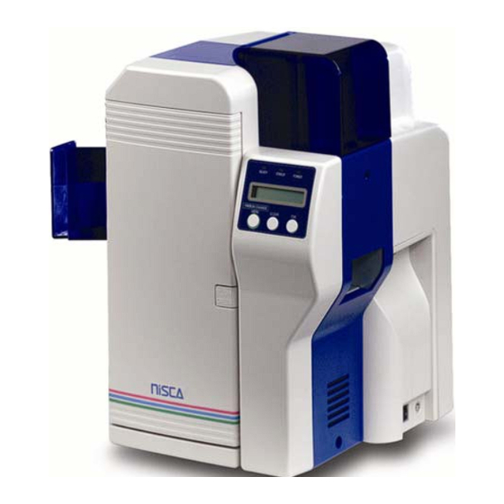
For Nisca Model PR5300
r
d
P
r
i
r
d
P
r
i
G
u
i
d
e
G
u
i
d
e
n
t
e
r
n
t
e
r
Advertisement
Table of Contents
Troubleshooting

Subscribe to Our Youtube Channel
Related Manuals for Nisca PR5300


Summary of Contents for Nisca PR5300
- Page 1 ’ ’ For Nisca Model PR5300 TEAMNisca, A Division of Kanematsu USA, Inc. 400 Cottontail Lane, Somerset, NJ 08873 Copyright © 2004, Kanematsu USA. All rights reserved. TEAMNisca® and the TEAMNisca® logo are a registered trademark of Kanematsu USA, Inc. Microsoft® and Windows®...
-
Page 3: Table Of Contents
Table of Contents Chapter 1: Introduction Welcome! ..........................1 About This User’s Guide ......................1 General Site Requirements .......................2 Important Safety Instructions ....................2 Electrical Requirements .....................3 Physical Requirements .......................3 Environmental Requirements .....................3 Chapter 2: Getting Started Printer Features ..........................4 Front of the Printer ......................4 Rear of the Printer ......................5 Printer LCD Panel ......................5 LCD Operation ........................6... - Page 4 Interpreting LCD Jam Messages .....................37 Card Appearance Issues ......................39 General Troubleshooting Suggestions ..................40 Where to Get Additional Help ....................40 Block Diagram ........................41 Appendix A: Printer specifications ................42 Appendix B: Printer Configuration ................44 Appendix C: User Mode Menu Map ................46 Appendix D: Parts Replacement ................
-
Page 5: Chapter 1: Introduction
C H A P T E R Introduction Welcome! Congratulations on your purchase of the Nisca PR5300 Direct Card Printer. The printer gives you brilliant images using these features: Full color edge to edge 300 dpi dye sublimation printing technology... -
Page 6: General Site Requirements
General Site Requirements When choosing a site for the PR5300, consider the following recommendations: Select a site that is out of direct sunlight. Placement should be on a sturdy platform and off the floor. -
Page 7: Electrical Requirements
Electrical Requirements The PR5300 requires the following electrical specifications for optimal performance: 100-240 VAC at 50/60 Hz. The PR5300 is auto-switching to power within this range. Single phase, 3-wire grounded receptacle. If you use an extension cord with the printer, verify it’s rated for a minimum of 125 VAC, 10 Amps. -
Page 8: Chapter 2: Getting Started
C H A P T E R Getting Started Printer Features Front of the Printer A. Front Access Panel Opens to allow access to the inside of the printer. B. Front Access Panel Release Button Button that allows the front access panel to open. C. -
Page 9: Rear Of The Printer
Rear of the Printer A. Circuit Breaker Protection device that stops current if there is a direct short or excessive heat. B. Interface Port Connection SCSI II, Parallel, USB C. Options Connector Port The printer supports the attachment of a optional card lamination module. D. -
Page 10: Lcd Operation
LCD Operation ITEM DESCRIPTION MODE FUNCTION LCD Display Normal Displays the printer’s status. User Displays the selected menu or values. Ready LED Green light indicates printer is ready and will accept data. Error LED Indicates an error has occurred. Power LED Indicates the power is On. -
Page 11: Unpacking The Printer
Unpacking the Printer Follow these steps to unpack the printer. Be sure to select a location that meets the general requirements as stated above. Caution IMPORTANT! The printer must be placed on a level surface, in a dust free environment. It is essential to be able to access the printer from all sides for its installation. -
Page 12: Loading The Ink Ribbon
5. Open the front access panel by depressing the release button and lift the green retaining lever. Gently remove the ribbon cartridge by sliding it toward the front of the printer. 6. Remove the print head packing material from the ribbon cartridge. Loading The Ink Ribbon Caution IMPORTANT! To prevent damage to the print head, you must press the Ribbon... - Page 13 1. Open the ribbon cartridge by sliding the release lever to the left. 2. Remove new ribbon from its packaging and place on the supply side of the ribbon cartridge. Take up Side Supply Side 3. Locate the empty ribbon bobbin packaged with the printer accessories and place on the take up side of the ribbon cartridge.
-
Page 14: Connecting The Printer
5. Advance the take up bobbin 2-3 turns to verify that the ribbon is properly seated on the bobbin and all slack has been removed from the ribbon. 6. Close the ribbon cartridge and slide the release lever to the right ensuring the cartridge is securely locked. -
Page 15: Parallel Connection
1. Make sure the computer and printer are turned off. 2. Each SCSI device to be connected in the SCSI chain must be identified with an individual ID number. There are 7 potential SCSI ID numbers to specify and each SCSI device must be assigned its own unique ID number. -
Page 16: Usb Connection
Note Use only a shielded, Type C, IEEE 1284 parallel port cable, up to a maximum of 6.5 feet long. 1. Make sure the printer and computer are turned off. 2. Connect the micro centronics connector to the printer’s parallel port, and snap the fastening clips into place. -
Page 17: Loading Cards
2. Connect the square end of the USB 2.0 cable into the printer USB connector. 3. Connect the other end into an available USB 2.0 port on the back of the computer. 4. Insert the power cord into the power receptacle on the rear of the printer. Plug the other end into an available wall outlet. -
Page 18: Card Size Adjustment
5. Once the cards are loaded, place the card weight on the top card with the raised bevel handle facing away from the printer. This card weight increases feeding reliability primarily when only a few cards are in the card feeder. 6. -
Page 19: Turning On The Printer
Windows® 2000 and Windows® XP, you must have Administrator privileges. The PR5300 printer comes with different printer drivers for the Microsoft operating systems. The printer driver is located on the installation CD that was included with your printer. Insert the CD into your computer’s CD drive. - Page 20 1. Click Next. 2. Read the license agreement and click Yes if you accept the terms of the license agreement. If you decline, you cannot install the driver. 3. Click Next. 4. Verify the printer port and name. 5. Click on the Detect ECP button and review the message that is displayed. Most new computers have the parallel port set to ECP (enhanced capability port).
- Page 21 Note If your computer’s parallel port is not set to ECP, you will experience slower print speeds. ECP is not available in Windows NT®. 6. Click Next. 7. Verify the components to install. 8. Click Next. 9. The setup application will now install and configure the printer driver. 10.
-
Page 22: Installing The Windows® 2000/Xp Print Driver Scsi
Windows® 2000 / Windows® XP SCSI Interface Installation 1. Insert the Nisca installation CD in your computer’s CD drive. 2. On the Start menu, click Run. 3. Type d:\setup, where d is the letter assigned to your CD drive. 4. Click OK. - Page 23 2. Read the license agreement and click Yes if you accept the terms of the license agreement. If you decline, you cannot install the driver. 3. Enter your customer information. 4. Click Next. 5. Enter the registration information for product warranty.
- Page 24 If the PR5300 printer is the last device on the SCSI bus, the termination switch must be set to ON. The printer driver may still be installed even though the printer was not detected.
-
Page 25: Print A Test Card
1. Turn on the power to the printer. Be sure the green LED on the LCD panel is lit and the LCD display shows normal mode. 2. Confirm that all supplies are loaded. 3. Click Start Programs Nisca PR5300 Printer Nisca ID. » » »... - Page 26 4. The sample application will load. 5. Select File Print. » 6. Select the Nisca printer you would like to use to print the sample. 7. Click OK to print the sample card.
-
Page 27: Chapter 3: Using The Printer
C H A P T E R Using the Printer Configuring Printer Preferences The PR5300 printer can be used with any Windows® software application. Settings that control the printing and personalization of the card are found under Printing Preferences. These settings include: To open the printer driver Printing Preferences, please refer to the following steps: Windows®... -
Page 28: Printer Option Tab
2. Click on the Nisca PR5300 card printer with the right mouse button, and select “Printing Preferences…”. 3. Change the settings desired for your application. Printer Options Tab Orientation Select either Portrait or Landscape. Selecting Portrait causes the card to print in the vertical orientation. -
Page 29: Lcd Modes Of Operation
Flip Card If an external module is inserted at the beginning of the print chain, the driver can force a particular side up on entry. Eject Card If an external unit is attached to the end of the print chain, the driver can force a particular side up on exit. -
Page 30: User Mode Information
When the printer is first powered ON, the printer’s initialization check will briefly appear and the printer will indicate “PLEASE WAIT, NOW INITIALIZING”. When completed, the green Ready indicator light will be illuminated. The LED lights work in conjunction with the printer’s LCD display to help communicate the status of the printer. -
Page 31: Chapter 4: Maintenance
C H A P T E R Maintenance Your Nisca PR5300 printer is built to require a minimum amount of maintenance. Nevertheless, there are a few procedures you need to perform on a regular basis or as needed to ensure maximum performance. -
Page 32: Manual Cleaning
1. Enter the User Mode by pressing and holding the Menu button for 3 seconds. 2. Press EXE and then use the Menu button to navigate to the Cleaning sub-menu. See User Mode Menu Map in Appendix C for navigation assistance. 3. -
Page 33: Cleaning The Takeup Roller
procedures should be performed periodically. The following identifies areas needed for manual cleaning. Cleaning the Takeup Roller The takeup roller automatically feeds the cards off the bottom of the stack into the printer. The takeup roller should be cleaned every 2,000 prints to help prevent card jams and maintain the best print quality. -
Page 34: Cleaning The Flip/Turn Transport Rollers
1. Open the front access panel by depressing the release button. 2. Grasp the input roller module tab, and pull it out of the printer. 3. Clean the rollers with an alcohol cotton swab in the direction pictured. 4. Once the dust and debris is cleaned from the rollers, place the assembly module back into the printer. -
Page 35: Cleaning The Print Unit Rollers
2. Remove the phillips screw on the left side of the printer to open the print unit door. Open the top cover and manually rotate the flip/turn transport roller 180° by moving the unit counter clockwise. 3. Advance the green knob and use an alcohol swab to clean the rubber and white plastic rollers. -
Page 36: Cleaning The Print Head
2. Clean each of the print unit rollers using a alcohol cotton swab. Cleaning the Print Head This procedure should be performed if you notice a streak on the card where color was not transferred and be performed approximately every 2,000 prints to maintain a consistent print quality. - Page 37 3. Open the front access panel by depressing the release button. Lift the green retaining lever and remove the ribbon cartridge. 4. Using a phillips screwdriver, remove the retaining bracket. 5. Press the metal latch to release the print head and gently slide the print head toward the front of the printer.
-
Page 38: Updating The Firmware
New firmware updates can be downloaded from the Nisca website at www.teamnisca.com and loaded into your printer using the “Download Utility” program. No physical replacement or repair of any parts is required, so this process is simple. - Page 39 2. Click Start Programs Nisca Download IEEENT Nisca Download IEEENT program. » » » The firmware update utility program will appear: 3. From the download utility program, click on the search button. This finds the printer attached to your computer.
-
Page 40: Chapter 5: Troubleshooting
C H A P T E R Troubleshooting This chapter offers explanations to potential problems you may experience with your PR5300 printer. The LCD will alert the operator and will display the error condition. The suggestions in this chapter should, in most cases, solve the problem. If you still have difficulty after trying these suggestions, contact your authorized reseller for technical assistance. -
Page 41: Interpreting Lcd Jam Messages
LCD SCREEN MESSAGE PROBABLE CAUSE ACTION Check whether high or low coercivity cards have been specified. Verify no debris is on the card and replace with another card. Print Card does not Exist An error has occurred during dual Press the clear button and side printing. - Page 42 Many jams can be fixed by keeping the rollers clean. See the PR5300 block diagram at the end of this appendix for clarification of the areas for jams. Refer to Chapter 4 for cleaning procedures. Warning IMPORTANT: Turn the printer power off to avoid electrical shock when clearing jams.
-
Page 43: Card Appearance Issues
LCD SCREEN MESSAGE PROBABLE CAUSE ACTION Press and hold the clear button to reset the printer Card Jam Remove the Card A card is jammed in the printer. Press and hold the clear button to reset the printer. If the card does not eject automatically, remove it manually. -
Page 44: General Troubleshooting Suggestions
Ensure “Enable bi-directional support” is activated. Where to get additional help If you work with an authorized Nisca distributor or value added reseller, contact your reseller for assistance. You may also contact us at one of the following sources: Telephone:... -
Page 45: Block Diagram
PR5300 Block Diagram Feeder Flip/Turn Encoder Print Unit... -
Page 46: Appendix A: Printer Specifications
A P P E N D I X Printer Specifications PR5300 Direct ID Card Printer Printing system 300 dpi, 24 bit continuous tone printing, 16.7 million colors Printing method Thermal transfer dye-sublimation Print medium PVC or polyester cards with polished PVC finish Medium size Card width/length: CR-80, 2.125”... - Page 47 2 year return to depot service printer warranty Warranty 1 year unlimited prints print head warranty Options PR5302 Laminator PR5301 Magstripe encoder RFID encoding (read/write, ready only RFID encoding capabilities differ depending on technology, please consult Team Nisca for more details.
-
Page 48: Appendix B: Printer Configuration
A P P E N D I X Printer Configuration ITEM NAME DESCRIPTION Card Feeder The cards automatically feed off the bottom of the stack. The slot is 1.5 times the thickness of the card to... - Page 49 ITEM NAME DESCRIPTION prevent double feeding. Input Roller Module Removes any debris from the surface of the card prior to entering the print unit. Flip/Turn Unit This unit flips the card over and switches the printing path from printed, rejected or encoded. Print Unit The card moves through this unit as the color and protective coating is applied.
-
Page 50: Appendix C: User Mode Menu Map
A P P E N D I X User Mode Menu Map COLOR USER MODE IMAGE SETUP ADJUSTMENT RIBBON TYPE MAIN MENU MENU MENU MENU Card Count Image Setup — Entry Color Adjustment — Ribbon Type — Entry Entry Total Count Color Adjustment Yellow Printer Ribbon... - Page 51 User Mode Menu Map (continued) PRINTER CLEANING PRINTER ROM VERSION SETUP DATA MENU STATUS MENU MENU RESET MENU Remove Normal Cards Printer Status — Base Program Setup Data Reset — Entry Entry Set Cleaning Card Memory Mode Main Program Setup Data Reset Mode selection Finish Return to Normal...
-
Page 52: Appendix D: Parts Replacement
A P P E N D I X Parts Replacement This printer is designed to provide excellent performance over time. In order to maintain your printer in peek performance, several parts should be replaced on a periodic basis. The following table outlines these parts and the suggested replacement time frame: PART NUMBER OF PRINTS... -
Page 53: Replacing The Print Head
2. Grasp the input roller module tab, and pull it out of the printer. 3. Clean the new input roller assembly before replacing it back in the printer. Clean with an alcohol cotton swab in the direction pictured. 4. Once the dust and debris is cleaned from the rollers, place the assembly module back into the printer. - Page 54 3. Open the front access panel by depressing the release button. Lift the green retaining lever and remove the ribbon cartridge. 4. Using a phillips screwdriver, remove the retaining bracket. 5. Press the metal latch to release the print head and gently slide the print head toward the front of the printer.
- Page 55 6. Gently remove the pin connector from the bottom of the print head. 7. Affix the connector to the new print head and reinstall in reverse order. 8. Insert the floppy disk that came with the print head. This data must be loaded to the print head before using the printer.
Need help?
Do you have a question about the PR5300 and is the answer not in the manual?
Questions and answers